

Page 1

Power Platform® 4300
TASKCard® 808
User’s Guide
P/N OM-4300-TASK808 Reprinted 7/98
Dranetz-BMI • 1000 New Durham Road • Edison, NJ 08818-4019
Telephone 1-800-372-6832 or 732-287-3680
Fax 732-248-1834 • www.dranetz-bmi.com
Page 2

PP4300/Task 808
WARNING
Death, serious injury, or fire hazard could result from improper
connection of this instrument. Read and understand this manual
before connecting this instrument. Follow all installation and
operating instructions while using this instrument.
Connection of this instrument must be performed in compliance
with the National Electrical Code (ANSI/NFPA 70-1996) of USA and
any additional safety requirements applicable to your installation.
Installation, operation, and maintenance of this instrument must be
performed by qualified personnel only. The National Electrical
Code defines a qualified person as "one familiar with the
construction and operation of the equipment and the hazards
involved."
ADVERTENCIA
Una conexi ón incorrecta de este instrumento puede producir la
muerte, lesiones graves y riesgo de incendio. Lea y entienda este
manual antes de conectar. Observe todas las instrucciones de
instalación y operaci ón durante el uso de este instrumento.
La conexi ón de este instrumento debe ser hecha de acuerdo con
las normas del Código El éctrico Nacional (ANSI/NFPA 70-1996) de
EE. UU., además de cualquier otra norma de seguridad
correspondiente a su establecimiento.
La instalaci ón, operación y mantenimiento de este instrumento
debe ser realizada por personal calificado solamente. El Código El
éctrico Nacional define a una persona calificada como "una que
esté familiarizada con la construcci ón y operación del equipo y
con los riesgos involucrados."
Page ii
Page 3

PP 4300/Task 808
AVERTISSEMENT
Si l'instrument est mal connecté, la mort, des blessures graves, ou
un danger d'incendie peuvent s'en suivre. Lisez attentivement ce
manuel avant de connecter l'instrument. Lorsque vous utilisez
l'instrument, suivez toutes les instructions d'installation et de
service.
Cet instrument doit être connecté conformément au National
Electrical Code (ANSI/NFPA 70-1996) des Etats-Unis et à toutes les
exigences de sécurité applicables à votre installation.
Cet instrument doit être installé, utilisé et entretenu uniquement par
un personnel qualifié. Selon le National Electrical Code, une
personne est qualifiée si "elle connaît bien la construction et
l'utilisation de l'équipement, ainsi que les dangers que cela
implique.”
WARNUNG
Der falsche Anschluss dieses Gerätes kann Tod, schwere
Verletzungen oder Feuer verursachen. Bevor Sie dieses
Instrument anschliessen, müssen Sie die Anleitung lesen und
verstanden haben. Bei der Verwendung dieses Instruments mü
ssen alle Installation- und Betriebsanweisungen beachtet werden.
Der Anschluss dieses Instruments muss in Übereinstimmung mit
den nationalen Bestimmungen für Elektrizität (ANSI/NFPA 70-1996)
der Vereinigten Staaten, sowie allen weiteren, in Ihrem Fall
anwendbaren Sicherheitsbestimmungen, vorgenommen werden.
Installation, Betrieb und Wartung dieses Instruments dürfen nur
von Fachpersonal durchgeführt werden. In dem nationalen
Bestimmungen für Elektrizität wird ein Fachmann als eine Person
bezeichnet, welche "mit der Bauweise und dem Betrieb des
Gerätes sowie den dazugehörigen Gefahren vertraut ist."
Page iii
Page 4

PP4300/Task 808
Page iv
Page 5
PP 4300/Task 808
Safety Summary
Definitions
WARNING statements inform the user that certain conditions or practices
could result in loss of life or physical harm.
CAUTION statements identify conditions or practices that could harm the
Power Platform, its data, other equipment, or property.
NOTE statements call attention to specific information.
Symbols
The following International Electrotechnical Commission (IEC) symbols
are marked on the top and rear panel in the immediate vicinity of the
referenced terminal or device:
!
Caution, refer to accompanying documents (this manual).
Direct current (DC) operation of the terminal or device.
Power Switch
Definiciones
Las ADVERTENCIAS informan al usuario de ciertas condiciones o prá
cticas que podrían producir lesiones mortales o daño físico.
Las PRECAUCIONES identifican condiciones o prácticas que podrían
dañar la Power Platform, sus datos, otros equipos o propiedad.
Las NOTAS llaman la atención hacia la información específica.
Page v
Page 6
PP4300/Task 808
Símbolos
Los siguientes símbolos de la Comisión Internacional Electrot écnica
(IEC) aparecen marcados en el panel superior y el posterior inmediatos
al terminal o dispositivo en referencia:
!
Precaución, consulte los documentos adjuntos (este manual).
Operación de corriente continua (CC) del terminal o dispositivo.
Interruptor de encendido
Définitions
Les messages d'AVERTISSEMENT préviennent l'utilisateur que
certaines conditions ou pratiques pourraient entraîner la mort ou des lé
sions corporelles.
Les messages de MISE EN GARDE signalent des conditions ou
pratiques susceptibles d'endommager “Power Platform”, ses données,
d'autres équipements ou biens mat ériels.
Les messages NOTA attirent l'attention sur certains renseignements spé
cifiques.
Symboles
Les symboles suivants de la Commission électrotechnique internationale
(CEI) figurent sur le panneau arrière supérieur situé à proximit é du
terminal ou de l'unit é cité:
!
Mise en garde, consultez les documents d'accompagnement (ce
manual).
Fonctionnement du terminal ou de l'unit écourant continu (CC).
Interrupteur de tension
Definitionen
WARNUNGEN informieren den Benutzer darüber, daá bestimmte
Bedingungen oder Vorgehensweisen körperliche oder tödliche
Verletzungen zur Folge haben können.
Page vi
Page 7

PP 4300/Task 808
VORSICHTSHINWEISE kennzeichnen Bedingungen oder
Vorgehensweisen, die zu einer Besch ädigung von Power Platform, seiner
Daten oder anderer Geräte bzw. von Eigentum führen können.
HINWEISE machen auf bestimmte Informationen aufmerksam.
Symbole
Die folgenden Symbole der Internationalen Elektrotechnischen
Kommission (International Electrotechnical Commission; IEC) befinden
sich auf der Abdeck- und Seitenplatte unmittelbar am betreffenden
Terminal oder Gerät.
!
Vorsichtshinweis, siehe Begleitdokumente (dieses Handbuch).
Gleichstrombetrieb im Terminal oder Gerät.
Netzschalter
Safety Precautions
The following safety precautions must be followed whenever any type of
connection is being made to the instrument.
o Connect the green safety (earth) ground first, before making any other
connections.
o When connecting to electric circuits or pulse initiating equipment, open
their related breakers. DO NOT install any connection of the
instrument on live power lines.
o Connections must be made to the instrument first, then connect to the
circuit to be monitored.
o Wear safety glasses and insulated gloves when making connections to
power circuits.
o Hands, shoes and floor must be dry when making any connection to a
power line.
o Make sure the unit is turned OFF before connecting probes to the rear
panel.
o Before each use, inspect all cables for breaks or cracks in the
insulation. Replace immediately if defective.
Page vii
Page 8

PP4300/Task 808
Medidas de seguridad
Las medidas de seguridad siguientes deberán observarse cuando se
realice cualquier tipo de conexión al instrumento.
o Antes de hacer cualquier conexión, deberá enchufarse el conector de
seguridad verde a tierra.
o Cuando se haga conexiones a circuitos eléctricos o a equipo de
activación por pulso, deberá abrirse sus respectivas cajas de
seguridad. NO deberá hacerse ninguna conexión del instrumento en
líneas eléctricas bajo tensión.
o Las conexiones deberán hacerse primero al instrumento y, luego, al
circuito a ser monitorizado.
o Al hacer conexiones a circuitos eléctricos, deberá utilizar anteojos y
guantes protectores.
o Sus manos, zapatos y el piso deberán estar secos en todo momento
en que se haga una conexión a un cable eléctrico.
o Verifique que la unidad esté DESACTIVADA antes de conectar
sondas en el panel posterior.
o Previo a cada uso, deberá verificarse que los cables no estén rotos y
que el material aislante no tenga rajaduras. Reemplace de inmediato
cualquier parte defectuosa.
Mesures de Sécurité
Les mesures de sécurité suivantes doivent être prises chaque fois qu’un
type de connexion quelconque est effectué sur l’instrument.
o Connecter d’abord la prise de terre de sécurité verte (terre) avant
d’effectuer toute autre connexion.
o Ouvrir les disjoncteurs correspondants lors d’une connexion à des
circuits électriques ou à des équipement de génération d’impulsions.
NE PAS effectuer de connexion d’instrument sur des lignes
électriques sous tension.
o Une fois toutes les connexions de l’instrument effectuées, connecter
au circuit à contrôler.
o Porter des lunettes de protection et des gants isolants pour effectuer
des connexions aux circuits électriques.
o S’assurer que les mains, les chaussures et le sol soient secs lors de
connexions à une ligne électrique.
o S’assurer que l’unité est ÉTEINTE avant de connecter les sondes au
panneau arrière.
o Inspecter tous les câbles, avant chaque utilisation, pour s’assurer que
les isolants ne sont pas coupés ou fendus. Remplacer immédiatement
tous les équipements défectueux.
Page viii
Page 9

PP 4300/Task 808
Sicherheitsvorkehrungen
Die folgenden Sicherheitsvorkehrungen sind immer dann zu befolgen,
wenn eine Verbindung zum Instrument hergestellt wird.
o Schließen Sie zuerst die grüne Sicherheits-/Erdleitung an, bevor Sie
eine andere Verbindung herstellen.
o Öffnen Sie beim Anschluß an elektrische Stromkreise oder
Impulsauslösungseinrichtungen die entsprechenden Unterbrecher. Es
dürfen KEINE Anschlüsse an das Instrument unter stromführenden
Spannungsleitungen montiert werden.
o Die Verbindungen müssen zuerst am Instrument und danach an der zu
überwachenden Schaltung hergestellt werden.
o Tragen Sie Schutzbrillen und Isolierhandschuhe, wenn Sie Anschlüsse
an den Stromkreisen vornehmen.
o Hände, Schuhe und Fußboden müssen trocken sein, wenn Sie
Anschlüsse an den Stromkreisen durchführen.
o Stellen Sie sicher, daß das Gerät AUSgeschaltet ist, bevor Sie an der
rückwärtigen Konsole Meßfühler anschließen.
o Prüfen Sie vor jedem Gebrauch alle Kabel auf Bruchstellen und Risse
in der Isolierung. Wechseln Sie schadhafte Kabel sofort aus.
Page ix
Page 10

PP4300/Task 808
Statements and Notices
Notice regarding proprietary rights
This publication contains information proprietary to Dranetz-BMI. By accepting
and using this manual, the user agrees that the information contained
herein will be used solely for the purpose of operating equipment of
Dranetz-BMI.
Copyright
This publication is protected under the copyright laws of the United States
Title 17 et seq. No part of this publication may be reproduced, transmitted,
transcribed, stored in a retrieval system, or translated into any language or
computer language, in any form, by any means, electronic, mechanical,
magnetic, optical, chemical, manual or otherwise, without the prior written
consent of Dranetz-BMI, 1000 New Durham Road, Edison, New Jersey
08818.
Copyright © 1997, Dranetz-BMI
All Rights Reserved. Printed in the United States of America.
Revision rights
Dranetz-BMI reserves the right to revise this publication from time to time
and to make changes in its content without any obligation of notifying
previous users of such revisions or changes.
Trademarks
Power Platform, TASKCard, Scope Mode, DRAN-LINK, DRAN-VIEW
and Task 808 are registered trademarks of Dranetz-BMI.
Statement of reliability
The information in this manual has been reviewed and is believed to be
entirely reliable, however, no responsibility is assumed for any
inaccuracies. All material is for informational purposes only and is subject
to change without prior notice.
Continued on next page
Page x
Page 11

PP 4300/Task 808
Statements and Notices, continued
Statement of warranty
All products of Dranetz-BMI are warranted to the original purchaser
against defective material and workmanship for a period of one year from
the date of delivery. Dranetz-BMI will repair or replace, at its option, all
defective equipment that is returned, freight prepaid, during the warranty
period. There will be no charge for repair provided there is no evidence
that the equipment has been mishandled or abused. This warranty shall
not apply to any defects resulting from improper or
inadequate maintenance, buyer-supplied hardware/software interfacing,
unauthorized modification or misuse of the equipment, operation outside
of environmental specifications, or improper site preparation or
maintenance.
Notice regarding FCC compliance
This device has been tested and found to comply with the limits for a
Class A digital device, pursuant to Part 15 of the FCC Rules. These limits
are designed to provide reasonable protection against harmful
interference when the equipment is operated in a commercial
environment. This equipment generates, uses, and can radiate radio
frequency energy and, if not installed and used in accordance with the
instruction manual, may cause harmful interference to radio
communications. Operation of this equipment in a residential area is likely
to cause harmful interference in which case the user will be required to
correct the interference at his/her own
expense.
Page xi
Page 12

PP4300/Task 808
TABLE OF CONTENTS
SAFETY SUMMARY......................................................................................V
CHAPTER 1 GETTING STARTED..............................................................1
1.1 Introduction..............................................................................................1
1.2 Unpack The PP4300...............................................................................1
1.3 Check Contents......................................................................................2
1.3.1 Standard Accessories.......................................................................2
1.3.2 Inspect for Damage............................................................................2
1.3.3 Return Shipment.................................................................................2
CHAPTER 2 INTRODUCTION TO THE PP4300/TASK 808..................3
2.1 PP4300.......................................................................................................3
2.2 The Task 808 Application.....................................................................3
2.2.1 Task 808 Model Options ...................................................................3
2.2.2 Task 808 Power Circuit Configurations...........................................4
2.2.4 EASY START
TM
Feature...................................................................5
2.2.5 DRAN-LINK and DRAN-VIEW..........................................................5
2.2.6 Memory Cards (optional)...................................................................5
CHAPTER 3 HARDWARE OVERVIEW.....................................................7
3.1 PP4300.......................................................................................................7
3.1.1 Front and Bottom Panels...................................................................9
3.1.2 Top, Right and Left Panels.............................................................10
3.1.3 Back Panel.......................................................................................11
3.1.4 PP4300 Power Requirements.......................................................11
3.2 The Task 808.........................................................................................12
3.2.1 TASKCard Installation ......................................................................12
CHAPTER 4 TOURING THE TASK 808.................................................15
4.1 Preparing for the Guided Tours…...................................................15
4.2 Screen layout........................................................................................15
Page xii
Page 13

PP 4300/Task 808
4.3 Navigation Tips.....................................................................................16
4.3.1 Using SOFTKeys.............................................................................16
4.3.2 Numbered Options ..........................................................................17
4.3.3 Highlight Bar.....................................................................................17
4.4 Data Entry..............................................................................................18
4.4.1 Alphabetic Entry...............................................................................18
4.4.2 Numeric Entry...................................................................................18
4.5 Help Screens.........................................................................................18
CHAPTER 5 EASY START TOUR...........................................................21
5.1 Prepare the PP4300..............................................................................22
5.2 Connect the probes..............................................................................22
5.3 Power ON the PP4300.........................................................................23
5.4 Easy Start -- Configure/Monitor........................................................25
5.5 Viewing Data/Reports.........................................................................31
5.5.1 Viewing Scope Mode.......................................................................31
5.5.2 Viewing in Meter Mode....................................................................32
CHAPTER 6 ADVANCED TOUR.............................................................35
6.1 Setup Menu...........................................................................................36
6.1.1 Easy Start..........................................................................................36
6.1.2 Set Programmable Features...........................................................36
6.1.3 Turn Monitoring ON/OFF..................................................................38
6.1.4 Memory Functions ...........................................................................38
6.1.5 Set Input Configurations..................................................................45
CHAPTER 7 REPORTING TOUR............................................................53
7.1 View Data...............................................................................................54
7.2 Meter Mode............................................................................................64
7.3 Viewing Harmonics..............................................................................68
7.4 Screen Printing.....................................................................................69
APPENDIX A PRODUCT SUPPORT......................................................71
Page xiii
Page 14

PP4300/Task 808
A.1 Telephone Support..............................................................................71
A.2 Fax Line..................................................................................................71
A.3 World Wide Web...................................................................................71
A.4 Technical support email address....................................................71
APPENDIX B MAINTENANCE/SERVICING/RETURN SHIPMENT..73
B.1 Maintenance/Servicing.......................................................................73
B.1.1 Internal Battery Pack Replacement................................................73
B.1.2 Calibration........................................................................................77
B.3 Return Shipment..................................................................................77
B.3.1 Shipping Address............................................................................78
APPENDIX C OPTIONAL ACCESSORIES............................................79
C.1 Introduction..........................................................................................79
C.2 Optional Accessories List.................................................................79
C.2.1 Optional Accessories Descriptions...............................................80
C.3 Ordering information..........................................................................84
APPENDIX D PP4300 TECHNICAL SPECIFICATIONS.....................85
D.1 Overview.................................................................................................85
D.1.1 Dimensions ......................................................................................86
D.1.2 Environmental ...................................................................................86
D.1.3 System Time Clock.........................................................................86
D.1.4 Memory.............................................................................................86
D.1.5 Memory Card...................................................................................86
D.1.6 Power Requirements.......................................................................86
D.1.7 Input Resistance...............................................................................87
D.1.8 Installation Categories.....................................................................87
D.2 Interfaces...............................................................................................87
D.2.1 Display..............................................................................................87
D.2.2 Alarm.................................................................................................87
D.3 Measured Parameters........................................................................87
D.3.1 Voltage..............................................................................................87
D.3.2 Current..............................................................................................88
Page xiv
Page 15

PP 4300/Task 808
D.3.3 Phase................................................................................................88
D.3.4 Frequency.........................................................................................88
D.3.5 Environmental...................................................................................88
D.4 Computed Parameters.......................................................................89
D.4 1 Update Rate .....................................................................................89
D.4.2 ABC Volts.........................................................................................89
D.4.3 ABC Amps........................................................................................89
D.4.4 Real Power.......................................................................................89
D.4.5 Apparent Power...............................................................................90
D.4.6 Reactive Power................................................................................90
D.4.7 Environmental...................................................................................90
D.5 Resetting the PP4300 to the Factory Configuration..................91
D.5.1 Configurations..................................................................................91
APPENDIX E CONNECTING PROBES/COMMON CIRCUIT
CONNECTIONS ............................................................................................93
E.1 Making Voltage Connections...........................................................93
E.1.1 Safety Precautions..........................................................................95
E.1.2 Connection guidelines....................................................................98
E.1.3 Single phase connection example ................................................98
E.1.4 Neutral to ground connection example........................................100
E.2 Connecting a Current Probe..........................................................101
E.2.1 Safety Precautions........................................................................101
E.2.2 Available probes...........................................................................102
E.2.3 Reference to Channel Input..........................................................103
E.2.4 Connection Guidelines.................................................................104
E.2.5 Single phase current probe example..........................................104
E.3 Common Circuit Connections.......................................................105
E.3.1 Overview ..........................................................................................105
E.3.2 Safety Precautions.........................................................................105
E.3.3 Voltage and current connections..................................................107
E.3.4 Phasor diagrams............................................................................107
E.3.5 Verifying Voltage and Current Connections................................108
E.4 Single Phase.......................................................................................111
E.4.1 Introduction......................................................................................111
E.4.2 Connection diagram......................................................................111
E.4.3 Single Phase Phasor Diagrams...................................................111
E.5 Split Phase..........................................................................................112
Page xv
Page 16

PP4300/Task 808
E.5.1 Introduction ......................................................................................112
E.5.2 Connection diagram......................................................................112
E.5.3 Split Phase Phasor Diagrams......................................................112
E.6 Open Leg Delta..................................................................................113
E.6.1 Introduction ......................................................................................113
E.6.2 Connection diagram......................................................................113
E.6.3 Open Leg Delta Phasor Diagrams..............................................114
E.7 Four Wire Wye....................................................................................115
E.7.1 Introduction ......................................................................................115
E.7.2 Connection diagram......................................................................115
E.7.3 Four Wire Wye Phasor Diagrams................................................116
E.8 High-Leg Delta...................................................................................117
E.8.1 Introduction ......................................................................................117
E.8.2 Connection diagram......................................................................117
E.8.3 High Leg Delta Phasor Diagrams................................................118
E.9 Floating or Grounded Delta............................................................119
E.9.1 Introduction ......................................................................................119
E.9.2 Connection diagram......................................................................119
E.9.3 Floating or Grounded Delta Phasor Diagrams...........................120
E.10 Two-and-a-half Element................................................................121
E.10.1 Introduction...................................................................................121
E.10.2 Connection Diagram...................................................................121
E.10.3 Two-and-a-half Element Phasor Diagrams..............................122
E.11 Connecting to PTs and CTs.........................................................123
E.12 Connecting to a Potential Transformer (PT)............................124
E.12.1 Definition .......................................................................................124
E.12.2 Connections .................................................................................124
E.12.3 Procedure.....................................................................................125
E.12.4 Scale factor..................................................................................125
E.13 Connecting to a Current Transformer (CT)..............................125
E.13.1 Safety Precautions ......................................................................125
E.13.2 Description...................................................................................127
E.13.3 Types of CTs................................................................................127
E.14 Connecting to an Isolated Current Transformer (ISO)..........127
E.14.1 Introduction...................................................................................127
E.14.2 Safety Precautions ......................................................................127
E.14.3 Connections to ISO box..............................................................129
Page xvi
Page 17

PP 4300/Task 808
E.14.4 Applications..................................................................................129
E.14.5 ISO box connection to a current transformer.............................129
APPENDIX F MEMORY CARD FUNCTIONS......................................131
F.1 Memory Card Battery Replacement...............................................131
F.1.1 Introduction......................................................................................131
F.1.2 Battery check..................................................................................132
F.1.3 Battery types...................................................................................132
F.1.4 Battery Safety Precautions............................................................132
F.1.5 Replacement procedure................................................................134
F.2 Memory Card Formatting..................................................................135
F.2.1 Memory Card..................................................................................135
F.2.2 Memory Card Formatting Procedure...........................................135
APPENDIX G OPERATOR-REPLACEABLE PARTS........................137
G.1 Introduction........................................................................................137
G.2 To order parts.....................................................................................137
G.3 Parts List..............................................................................................137
APPENDIX H SYSTEM MESSAGES (PP4300)...................................139
H.1 Introduction........................................................................................139
H.2 Message Types..................................................................................139
H.2.1 Overview ..........................................................................................139
H.2.2 One-line messages........................................................................139
H.2.3 Full screen messages....................................................................139
H.3 Messages............................................................................................141
H.3.1 One-line messages........................................................................141
H.3.2 Full screen message......................................................................141
H.4 TASKCard error messages.............................................................142
INDEX...........................................................................................................143
Page xvii
Page 18

PP4300/Task 808
About this Manual…
The objectives pursued in designing and writing this manual were twofold:
1) to provide easy-to-follow, step-by-step “how to” instructions for firsttime users of the Power Platform 4300 with the Task 808, and
2) to provide more experienced users with comprehensive reference
documentation presented in an easy-to-find format.
Although the PP4300/Task 808 offers many powerful features, it is not a
complicated instrument. Learning to use the Task 808 should not be
complicated either. This manual incorporates structure, layout, fonts,
graphics and lean prose – all designed to make this learning process as
quick and as helpful as possible.
Organization
Basically, the information in this manual is organized into three major
segments:
Chap 1 - 4 Introductory “getting started” material
Chap 5 - 7 Guided Tour material, featuring three tours:
Easy Start Tour
Advanced Tour
Reporting Tour
Appendices -Reference material – lots of details
Page xviii
Page 19

Chapter 1 Getting Started
TASK 808
Chapter 1 Getting Started
1.1 Introduction
The Task 808 is one of a series of TASKCard-based applications from
Dranetz-BMI. The Power Platform 4300 serves as the hardware platform
for various applications, each of which is stored on PCMCIA-compatible
memory cards called TASKCards. Optional memory cards are available
for supplementary data storage.
Task 808 applications include:
o Demand and energy surveys
o Power Factor studies
o General three phase volt-ammeter measurements
o Performance qualification
o Sub-metering
o Power use trends establishment
o Metering/utility meter verification
o Nameplate data certification
o Detection of overloaded feeders
o Tracking facility efficiency vs. production output
o Transformer and neutral conductor derating
1.2 Unpack The PP4300
Open the carton carefully. Check the carton inventory and inspect the
contents for possible shipping damage.
o Remove all literature, including warranty card
o Remove the PP4300 from the carton
o Remove all accessories from the carton
NOTE - You may wish to save packing cartons and materials to use in the
event return shipment is required at some future date (for calibration, etc.).
Page 1
Page 20
Chapter 1 Getting Started
TASK 808
1.3 Check Contents
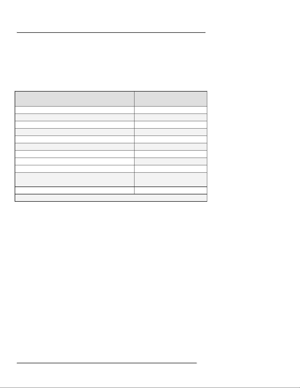
Check that the PP4300 and all of the standard accessories are included:
1.3.1 Standard Accessories
Description Part Number
AC Adapter/Battery Charger 116297-G1
Cable Pouch 116043-G1
Carrying Strap 116040-G1
Easel 116038-G1
Measurement Cable Set, w/Alligator Clips 116042-G1
User’s Guide OM-4300-TASK808
*Power Cord, Shielded, 115 Vac 110893-G1
*Power Cord, Shielded, 230 Vac (Euro) 115369-G1
*Power Cord, Shielded, 230 Vac (UK) 115368-G1
TASKCard 808 M (or H-M) TASK808M, or
TASK808/H/M
Wire Marker Set 155520
*User specified, one standard only.
n Refer to Appendix C for a complete listing of optional accessories for
the Task 808. Make sure all optional accessories ordered are included
in the package. If any items are missing, contact the Dranetz-BMI
Customer Service Department.
1.3.2 Inspect for Damage
Visually inspect the PP4300 and all accessories for any shipping
damage. If unit has been damaged in any way, first notify and file an
insurance claim with your carrier or underwriter or both.
1.3.3 Return Shipment
n Refer to Appendix B Maintenance/Servicing/Return Shipment for
important instructions regarding return shipment of any damaged
items.
Page 2
Page 21

Chapter 2 Introduction
TASK 808
Chapter 2 Introduction to the PP4300/Task
808
The Task 808 is a TASKCard-based PP4300 application. The patented
TASKCard is a removable flash memory card that is installed in the
PP4300 and contains an operating system designed for a specific
application (task).
2.1 PP4300
The Dranetz-BMI Power Platform 4300 is a portable, hand-held,
TASKCard based, eight-channel power meter/monitor. The PP4300 is
capable of monitoring, recording and displaying data for four voltage and
four current channels simultaneously.
n Refer to Chapter 3 Hardware Overview for illustrations and detailed
descriptions of the various controls, indicators, and connectors.
2.2 The Task 808 Application
The Task 808 is an application designed primarily for long-term demand
and energy surveys. It is intended for use by electrical facilities plant
personnel (engineers as well as electricians), energy management
consultants and utility marketing services groups.
2.2.1 Task 808 Model Options
Two Task 808 models are available: the 808/M (Memory ) with expandable
memory and the 808/H-M (Harmonics-Memory).
NOTE - Any model-specific differences in descriptions or procedures
will be documented throughout this manual.
Task 808 - model M
This model (808/M) provides all standard features, including 256K
internal memory , plus memory card storage capability. Optional memory
cards are available in various capacities, shown in Appendix C.
Page
3
Page 22

Chapter 2 Introduction
TASK 808
Task 808 - model H-M
In addition to all standard features, including 256K internal memory and
memory card storage capability, this model (808/H-M) provides
harmonics data, useful for determining the source and level of the effects
created, e.g., by the many energy conservation devices in use today, such
as electronic lighting ballasts and adjustable speed drives.
2.2.2 Task 808 Power Circuit Configurations
When TASKCard 808-equipped, the PP4300 can monitor any of the
following power circuit configurations:
o Single phase
o Split phase
o Four wire wye
o Floating or grounded delta
o Open leg delta
o High leg delta
o Two-and-a-half element
• WARNING: Refer to Appendix E Connecting Probes/Common
Circuit Connections for detailed descriptions of common power
monitoring configurations and probe connections.
• ADVERTENCIA: Consulte el Apéndice E Conexión de
sondas/Conexión de circuitos comunes para obtener
descripciones detalladas sobre configuraciones comunes de
monitorización eléctrica y conexiones de sondas.
• AVERTISSEMENT: Se reporter à l’Annexe E, Connexion des
sondes / Connexions simples des circuits, pour de plus amples
détails concernant les configurations de contrôle de puissance
et les connexions des sondes.
• WARNUNG: Im Anhang E “Meßfühler verbinden/ Gängige
Schaltverbindungen” finden Sie ausführliche Beschreibungen
von gängigen Konfigurationen der Spannungsüberwachung
und von Meßfühlerverbindungen.
While monitoring any of the above configurations (except the three delta
configurations), the PP4300 can also be connected to monitor neutral-toground voltage and neutral or ground current.
Page 4
Page 23

Chapter 2 Introduction
TASK 808
2.2.4 EASY START
TM
Feature
Both Task 808 versions come equipped with the EASY START feature
which prompts users for a few key items of information about the circuit
being monitored. EASY START programmatically steps the user through
the implementation of a basic setup. The system automatically turns on
the correct channel(s) and begins monitoring.
2.2.5 DRAN-LINK and DRAN-VIEW
The PP4300/Task 808 can transfer recorded data to a personal
computer for subsequent analysis by DRAN-VIEW (PC software for
graphic display of Task 808 data) using either an optional memory card
reader or optional isolated communications adapter and DRAN-LINK.
n Refer to Appendix C Optional Accessories for a description of these
options.
2.2.6 Memory Cards (optional)
An optional memory card may be used with the PP4300 to provide a
removable, rugged, compact, solid state mass storage device. Memory
cards are used to store events and setups.
Memory cards use low power and have an internal battery for data
retention. Various capacities are available, see Appendix C.
The PP4300 treats memory cards much like PCs treat floppy disks,
storing files in a DOS format.
n Refer to Chapter 6 Advanced Tour for a complete overview of
memory functions.
Page
5
Page 24

Page 25

Chapter 3 Hardware Overview
TASK 808
Chapter 3 Hardware Overview
This chapter illustrates and describes the key hardware features of the
Power Platform 4300 and the TASKCard 808.
3.1 PP4300
The PP4300 is a self-contained, portable instrument weighing less than 4
pounds and measuring 8" (20.3 cm) high by 12" (30.5 cm) wide by 2.5"
(6.4 cm) deep.
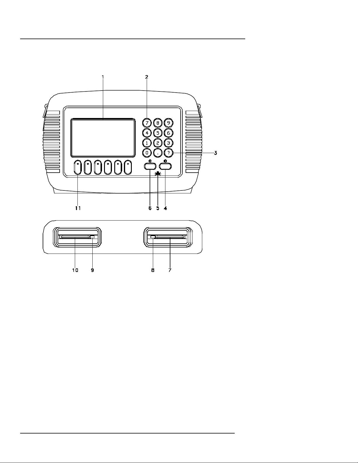
The front panel contains the display area, SOFTKeys and keypad. The
bottom panel contains two slots: one (on the left) for a TASKCard and one
(on the right) for an optional memory card.
The top panel contains the input voltage and current connectors. The left
and right side panels contain the optical interface port and AC adapter/dc
input connector, respectively, along with rings for attaching the supplied
carrying strap.
Page
7
Page 26
Chapter 3 Hardware Overview
TASK 808
Front and Bottom Panels
Page 8
Page 27

Chapter 3 Hardware Overview
TASK 808
3.1.1 Front and Bottom Panels
The illustration on the facing page references the following items:
1 Liquid Crystal Display (LCD). Provides 240 by 128 pixels (dots) of text
and graphic information. Has electroluminescent (EL) backlighting for
low light level viewing.
2 Numeric keypad. Consists of keyboard keys 0 through 9 and decimal
point (.) Permits menu selection and numerical data entry.
3 Question mark key. Displays Help screen with reference to screen
displayed at any time.
4 LCD contrast adjustment key. Symbol: Press and hold for
continuous contrast range change, release to stop. Press and quickly
release for incremental contrast change.
5 Battery charge indicator. LED glows continuously while battery is
charging and flashes when fully charged. Symbol:
6 ON/OFF Power Key. Symbol: Push for ON, push for OFF
7 Memory (data) card slot.
8 Memory card release. Ejects memory card.
9 TASKCard release. Ejects TASKCard.
10 TASKCard slot.
11 SOFTKeys. Six keys used to select options that appear on bottom of
screen. Function selected varies with screen displayed.
Page
9
Page 28
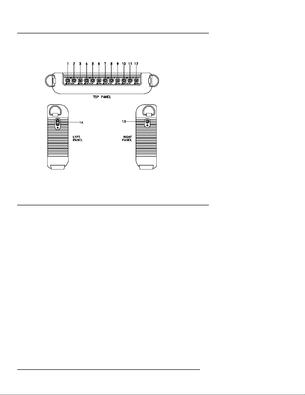
Chapter 3 Hardware Overview
TASK 808
3.1.2 Top, Right and Left Panels
4300 - 18A
Top panel connectors, from left to right (1 through 12), as shown
above:
1 CH A, + Differential Voltage Input Connector; red
2 CH A, - Differential Voltage Input Connector; white
3 CH A, PROBE, Current Input Connector
4 CH B, + Differential Voltage Input Connector; yellow
5 CH B, - Differential Voltage Input Connector; white
6 CH B, PROBE, Current Input Connector
7 CH C, + Differential Voltage Input Connector; blue
8 CH C, - Differential Voltage Input Connector; white
9 CH C, PROBE, Current Input Connector
10 CH D, + Differential Voltage Input Connector; gray
11 CH D, - Differential Voltage Input Connector; white
12 CH D, PROBE, Current Input Connector
Side panel connector/port, (13 and 14), as shown above:
13 AC Adapter/Bat tery Charger DC Input Connector
14 Optical Serial Data Port
Page 10
Page 29
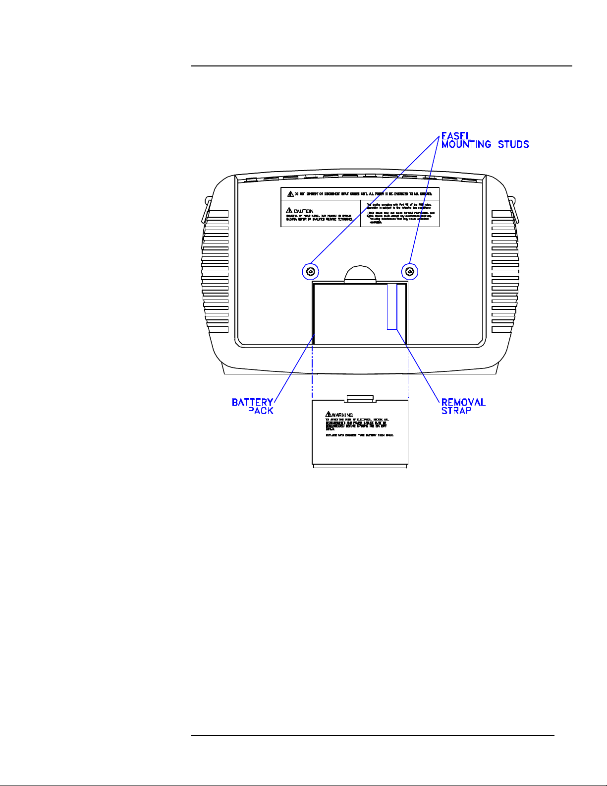
3.1.3 Back Panel
Chapter 3 Hardware Overview
TASK 808
3.1.4 PP4300 Power Requirements
The PP4300 can be operated using either its internal battery pack or the
AC Adapter/Battery Charger. Always charge the battery fully before use.
The PP4300 will always operate with the AC Adapter/Battery Charger,
regardless of the state of charge of the battery.
Charging Battery
Charge the battery pack by connecting the AC adapter output cable to the
DC INPUT connector on the right side of the PP4300. Connect the AC
adapter power cord to an appropriate outlet. A depleted battery pack can
be recharged in 2 hours with the unit OFF and 24 hours with the unit on.
The battery charge indicator glows continuously while charging and
flashes when fully charged. The indicator light functions only when the unit
is turned off and the AC adapter is properly connected.
Page
11
Page 30
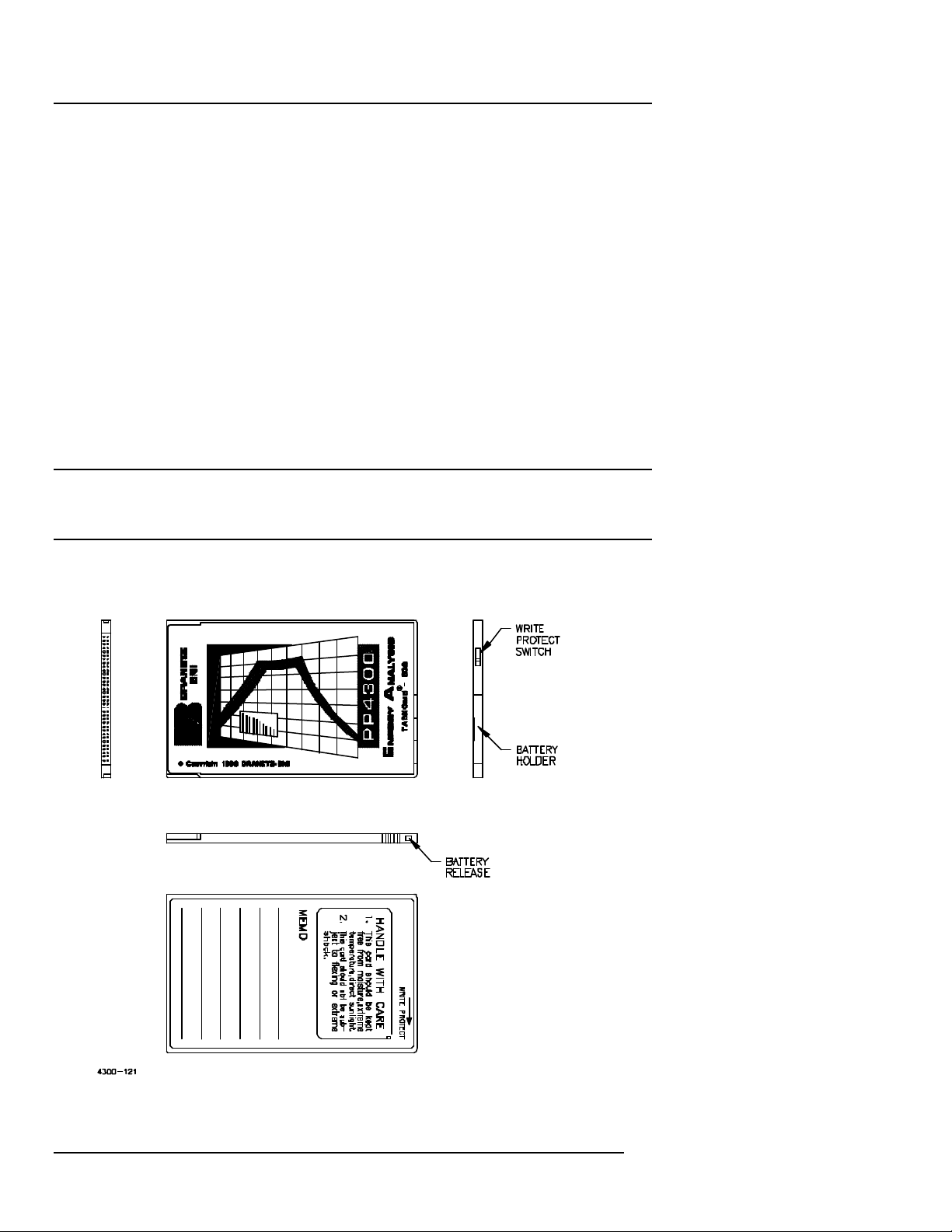
Chapter 3 Hardware Overview
TASK 808
Length of operation
The PP4300 can operate on a fully charged battery pack for up to four
hours. A screen warning will appear during operation when battery charge
is low.
AC Power
The PP4300 can be operated from a 50/60 Hz VAC power source using
the AC adapter, with or without the battery pack installed.
3.2 The Task 808
3.2.1 TASKCard Installation
Follow these simple steps to install the Task 808 TASKCard.
Step 1 Make sure that the PP4300 is powered OFF. I f already ON,
press the PP4300 ON/OFF power key to turn unit OFF.
Step 2 Remove TASKCard from its protective holder and check that
the plug end of card is clean and free of any obstruction.
Page 12
Page 31

Chapter 3 Hardware Overview
TASK 808
If plug end of card is dirty, clean with static-free, dry, low
pressure air to remove any foreign material causing obstruction
of the plug holes.
Step 3 Verify that the write protect switch (end opposite plug end) is
set to the write protect position. Use a pencil point to move the
switch to correct position, if required.
Step 4 At the bottom of the unit, position the TASKCard with the label
facing front and the plug end facing the TASK CARD slot in the
PP4300.
Step 5 Insert the card fully into the slot until resistance is felt, then press
firmly until card engagement is felt.
NOTE - Do not force the card into the slot if no card engagement is felt.
Remove card and check that there is no foreign object on or in the plug
end of the card. Remove any obstruction. Reinsert card and repeat card
engagement process. If card cannot be engaged, call Dranetz-BMI
Customer Service for instructions.
n Refer to Appendix H System Messages for description of TASKCard
Error Messages which may be displayed when the unit is powered
ON.
Page
13
Page 32

Page 33
Chapter 4 Touring the Task 808
TASK 808
Chapter 4 Touring the Task 808
4.1 Preparing for the Guided Tours…
Before jumping into the setup and operation of the Task 808, it is well
worth taking a minute or two to review a few simple preliminaries which
will help you get started when you begin the Guided Tours.
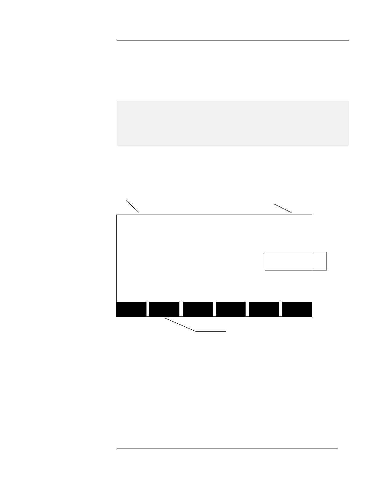
4.2 Screen layout
All of the Task 808 screens have common elements, such as the following:
Date Time
Oct-17-96 18:34:45
CIRCUIT TYPE
SINGLE PHASE
SINGLE SPLIT 3PHASE 3PHASE 2-1/2
PHASE PHASE DELTA WYE ELEMNT EXIT
Display Area
Reverse Highlight Text
Instructions (SOFTKeys)
Page
15
Page 34
Chapter 4 Touring the Task 808
TASK 808
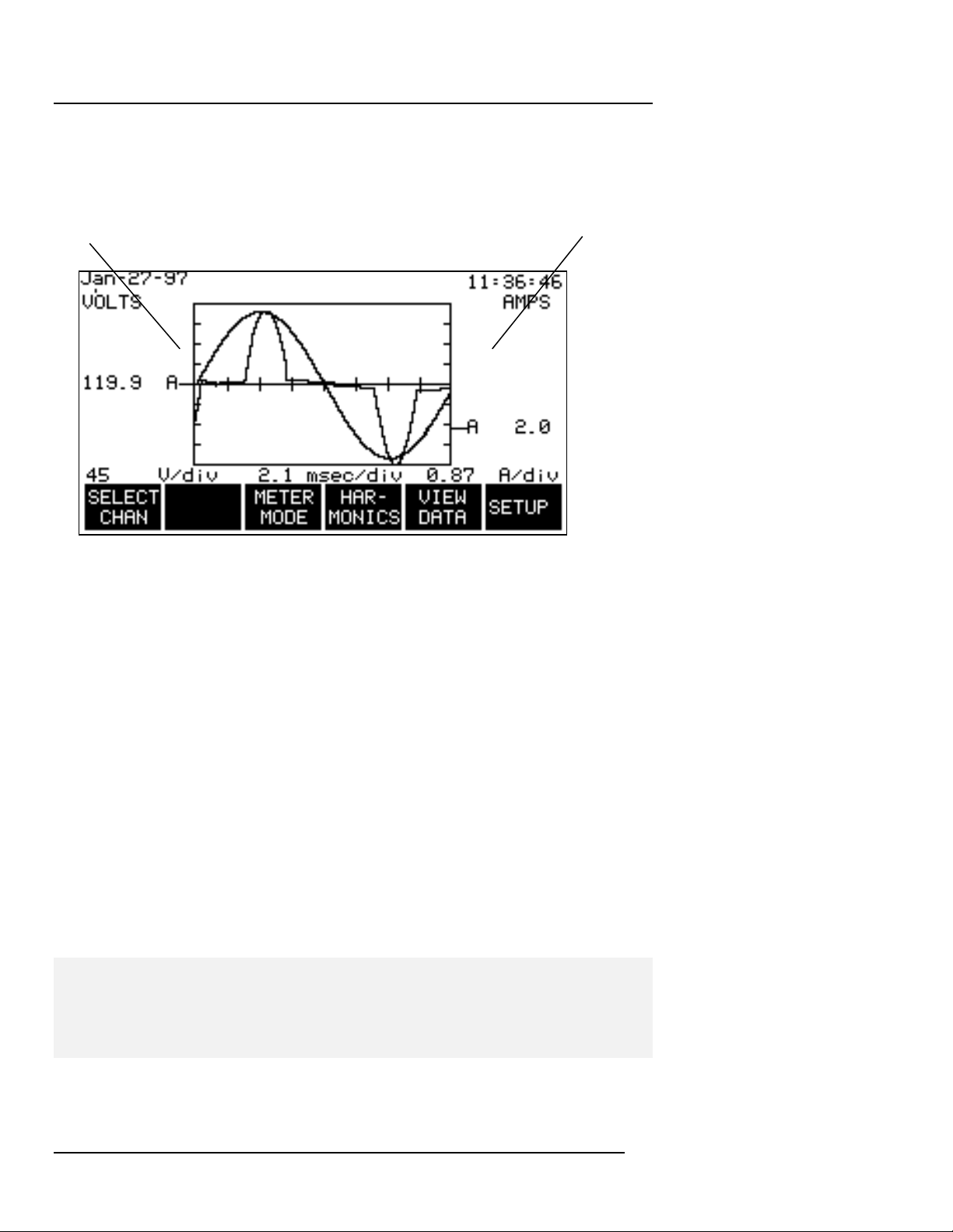
In addition, whenever a graph is displayed, the vertical axis (and scale) for
Volts will always be the left axis and the vertical axis (and scale) for Amps
will always be the right axis, as shown below:
VOLTS AMPS
4.3 Navigation Tips
Navigation (moving from screen to screen) is accomplished in two ways:
1) Using SOFTKeys, sometimes in conjunction with the highlight bar, and
2) Selecting from numbered options.
4.3.1 Using SOFTKeys
The six keys on the PP4300 immediately below the display area are
called SOFTKeys and are used to execute the reverse highlight text
instruction (such as, SELECT CHAN, METER MODE, SETUP)
displayed immediately above each key.
Some SOFTKeys move the highlight from field to field within the display
area while other SOFTKeys are used to advance from screen to screen.
Other SOFTKeys perform operations, such as, turning features ON and
OFF.
NOTE - Throughout this manual, references to SOFTKeys and their
corresponding instructions will be combined into a single phrase, e.g.,
press the EXIT SOFTKey.
Page 16
Page 35
Chapter 4 Touring the Task 808
TASK 808
4.3.2 Numbered Options
Several screens consist of a list of numbered options. Simply press the
corresponding key on the PP4300’s numeric key pad to execute the
desired option, e.g., press the 1 key on the “Setup” menu to select Easy
Start:
Jan-17-97 18:34:45
SETUP MENU
1. EASY START
2. SET PROGRAMMABLE FEATURES
3. TURN MONITORING OFF
4. MEMORY FUNCTIONS
5. SET INPUT CONFIGURATIONS
SCOPE METER HAR- VIEW
MODE MODE MONICS DATA
4.3.3 Highlight Bar
Many screens consist of a highlight bar and a list of options with
associated values. SOFTKeys are used to highlight, toggle and select
values.
Jan-17-97 18:34:45
CHANNEL SELECTION
CHANNEL VOLTS AMPS
A ON ON
B ON ON
C ON ON
D ON ON
NEXT VOLTS AMPS
CHAN ON/OFF ON/OFF EXIT
In the example above, the NEXT CHAN SOFTKey is used to highlight and
select channels. The VOLTS ON/OFF and AMPS ON/OFF SOFTKeys
are used to toggle between ON and OFF. The EXIT SOFTKey will
implement the selection.
Page
17
Page 36
Chapter 4 Touring the Task 808
TASK 808
4.4 Data Entry
There are two different methods for manually entering data, depending on
whether the data is alphabetic or numeric.
4.4.1 Alphabetic Entry
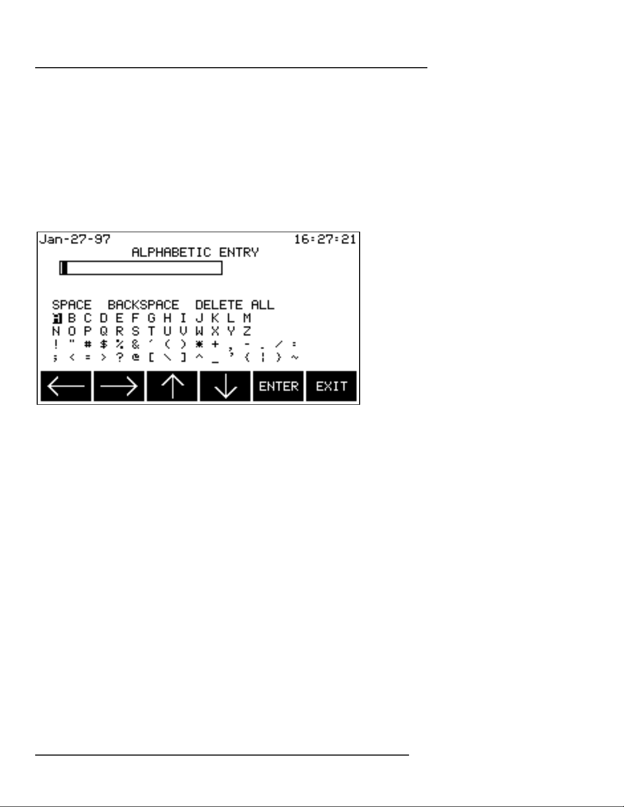
Alphabetic data must be entered to record the site/file name. Alphabetic
data is entered using the special alphabetic entry screen shown below
which will automatically be displayed when required:
The arrow SOFTKeys are used to highlight desired letters (and SPACE,
BACKSPACE, DELETE ALL). The ENTER SOFTKey moves highlighted
letters into the small text window at the top of the display area until the
site/file name is completed.
4.4.2 Numeric Entry
Integers (whole numbers) must be entered to record dates, times and
demand intervals. Decimals may be entered to record scale factors, sync
parameters, vertical scales and to describe the application. Integers and
decimals are entered using the numeric keys and the decimal point on the
PP4300’s numeric key pad.
4.5 Help Screens
Help screens are available for every screen in the application. Simply
press the ? key (question mark key) on the numeric keypad and help for
the active screen will be displayed.
Page 18
Page 37

Chapter 4 Touring the Task 808
TASK 808
On to the Guided Tours...
Now that the preliminaries are completed, continue with the Guided Tours
chapters to begin hands-on operation of the Task 808.
Chapters five, six and seven are designed to take the user step by step
through the complete setup and operation of the PP4300/Task 808:
Chapter 5 Easy Start Tour - designed to
implement a quick, no-frills setup using the programmed EASY
START feature.
Chapter 6 Advanced Tour - designed to
implement a more sophisticated setup by building on the Easy
Start setup.
Chapter 7 Reporting Tour - designed to
document the wide array of reporting features in the Task 808.
Recommendation
It is recommended that all three of the guided tours be taken, starting with
the Easy Start Tour.
Page
19
Page 38

Page 39

Chapter 5 EASY START Tour
The Easy Start Tour covers the following topics:
5.1 Prepare the PP4300
5.2 Connect the Probes
5.3 Power ON the PP4300
5.4 Easy Start -- Configuring/Monitoring
5.5 Viewing Data/Reports
Chapter 5 Easy Start Tour
TASK 808
Page
21
Page 40

Chapter 5 Easy Start Tour
TASK 808
5.1 Prepare the PP4300
Step 1 Insert the Task 808 TASKCard into the PP4300’s TASKCard slot.
n Refer to Chapter 3 Hardware Overview for complete TASKCard
installation instructions.
Step 2 Insert a formatted memory card (if applicable) into the PP4300’s
memory card slot.
n Refer to Appendix F Card Functions for complete memory card
installation and formatting instructions.
Step 3 Connect the AC adapter output cable to the DC INPUT connector
on the right side of the PP4300. Connect the AC adapter power cord to
an appropriate outlet.
5.2 Connect the probes
• WARNING: Refer to Appendix E Connecting Probes/Common
Circuit Connections for detailed descriptions of common power
monitoring configurations and probe connections.
• ADVERTENCIA: Consulte el Apéndice E Conexión de
sondas/Conexión de circuitos comunes para obtener
descripciones detalladas sobre configuraciones comunes de
monitorización eléctrica y conexiones de sondas.
• AVERTISSEMENT: Se reporter à l’Annexe E, Connexion des
sondes / Connexions simples des circuits, pour de plus amples
détails concernant les configurations de contrôle de puissance
et les connexions des sondes.
• WARNUNG: Im Anhang E “Meßfühler verbinden/ Gängige
Schaltverbindungen” finden Sie ausführliche Beschreibungen
von gängigen Konfigurationen der Spannungsüberwachung
und von Meßfühlerverbindungen.
Before powering ON and initiating the Easy Start tour, the probes must be
connected. Before connecting anything, make sure that the circuit to be
monitored has been de-energized.
Page 22
Page 41
Chapter 5 Easy Start Tour
TASK 808
5.3 Power ON the PP4300
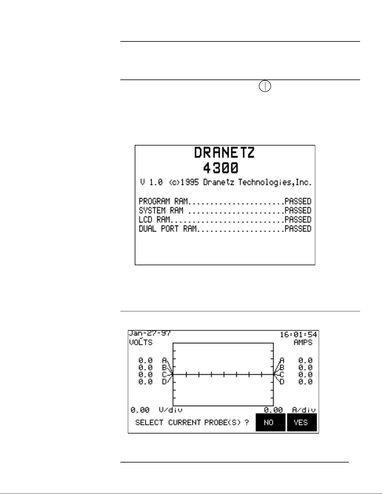
Step 1 Press the ON/OFF power button on the front panel of the
PP4300 to turn the power ON.
A screen with the results of self-diagnostic routines will be displayed
briefly during power up. All of the self-diagnostic routine results should
read PASSED.
n Refer to Appendix H System Messages for description of TASKCard
Error Messages which may be displayed when the unit is powered ON.
Step 2 Wait for the next screen to be displayed:
Page
23
Page 42
Chapter 5 Easy Start Tour
TASK 808
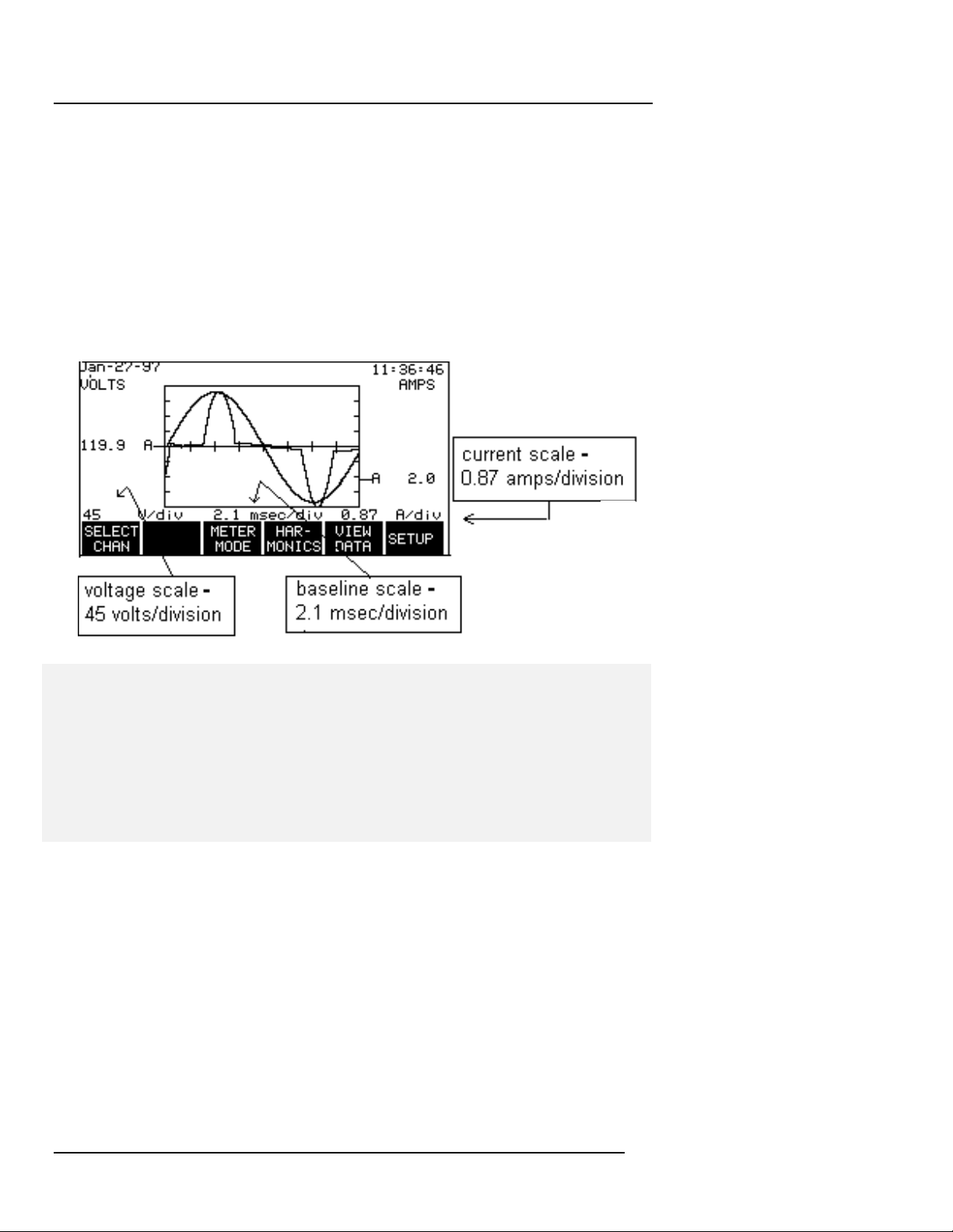
Depending on the PP4300 model in use, the message -- SELECT
CURRENT PROBE(S)? -- may be displayed across the bottom of the
screen, as a reminder, because correctly identified probe types and scale
factors are essential to accurate computations.
The “Scope Mode” screen is a gateway to four major functions of the
system: Meter Mode, Harmonics (available to Task 808/H-M model users
only), View Data and Setup. The “Scope Mode” screen also acts as a
home screen from which to branch to other functions of the Task 808.
NOTE - When the PP4300 is turned ON, it will always default to the
configuration values in effect when the system was last powered OFF.
Values for all eight channels will always be displayed initially on the “Scope
Mode” screen. If the probes are changed while the unit is OFF, all
monitored values will be erroneous until the probe and scale factor
information is updated.
The message – MONITORING: OFF -- may be displayed across the top
of this screen (and across all other screens as well). This message
indicates that the PP4300 is not monitoring any circuits, i.e., not recording
event data (however, the “Meter Mode,” “Scope Mode” and “Harmonics”
screens will still function properly with monitoring OFF). In addition to the
obvious, i.e., when the currently active configuration specifies that
monitoring is OFF, this message may also be displayed briefly under
such circumstances as saving a changed configuration or during the self
test. While monitoring is ON, no message is displayed.
Setting the time and date will be covered in the Advanced Tour.
Page 24
Page 43
Chapter 5 Easy Start Tour
TASK 808
5.4 Easy Start -- Configure/Monitor
Easy Start guides the user step-by-step through a basic configuration
process. The final step in the configuration process automatically initiates
the circuit monitoring.
Step 1 From the “Scope Mode” screen, press the NO SOFTKey to defer
selecting current probes until later on in the process. Press the SETUP
SOFTKey to get started.
Jan-17-97 18:34:45
SETUP MENU
1. EASY START
2. SET PROGRAMMABLE FEATURES
3. TURN MONITORING OFF
4. MEMORY FUNCTIONS
5. SET INPUT CONFIGURATIONS
SCOPE METER HAR- VIEW
MODE MODE MONICS DATA
Step 2 At the “Setup Menu,” press the 1 key on the numeric pad to begin
the Easy Start process.
The following message will be displayed:
Jan-17-97 18:34:45
CAUTION!
THE EASY START PROCESS WILL CHANGE
PREVIOUSLY PROGRAMMED INSTRUMENT
SETTINGS AND CONFIGURATIONS.
MONITORING IS ALSO SHUT DOWN
DURING EASY START PROGRAMMING.
PRESS CANCEL IF YOU DO NOT WANT TO
CHANGE EXISTING SETTINGS.
CON-
TINUE CANCEL
Page
25
Page 44
Chapter 5 Easy Start Tour
TASK 808
NOTE - The Guided Tours are designed for and are typically followed by
users with new PP4300/Task 808 units. If the Task 808 is currently
collecting data, you may wish to reschedule these tours when the Task
808 is idle.
Press the CONTINUE SOFTKey to display a list of circuit types.
Step 3 Select the desired circuit type by pressing the appropriate
SOFTKey.
Jan-17-97 18:34:45
CIRCUIT TYPE
3 PHASE DELTA
SINGLE SPLIT 3PHASE 3PHASE 2-1/2
PHASE PHASE DELTA WYE ELEMNT CANCEL
The following safety message will be displayed:
Jan-17-97 18:34:45
*** WARNING ***
IMPROPER CONNECTION OF THIS INSTRUMENT
COULD RESULT IN THE LOSS OF LIFE
PHYSICAL HARM, OR A FIRE HAZARD. ALSO
CONNECTION OF THIS INSTRUMENT MUST BE
PERFORMED IN COMPLIANCE WITH THE
NATIONAL ELECTRICAL CODE (ANSI/NFPA
70-1996) OR ANY OTHER ADDITIONAL
SAFETY REQUIREMENTS APPLICABLE TO YOUR
INSTALLATION. NEXT
**Continued On Next Screen SCREEN CANCEL
Press the NEXT SCREEN SOFTKey to continue. Another safety
message will be displayed:
Jan-17-97 18:34:45
Page 26
Page 45
Chapter 5 Easy Start Tour
TASK 808
*** WARNING ***
INSTALLATION, OPERATION, AND MAINTEN ANCE OF THIS INSTRUMENT MUST BE
PERFORMED ONLY BY QUALIFIED PERSONNEL.
THE NATIONAL ELECTRICAL CODE DEFINES
A QUALIFIED PERSON AS ONE FAMILIAR
WITH THE CONSTRUCTION AND OPERATION
OF THE EQUIPMENT AND THE HAZARDS
INVOLVED.
NEXT
SCREEN CANCEL
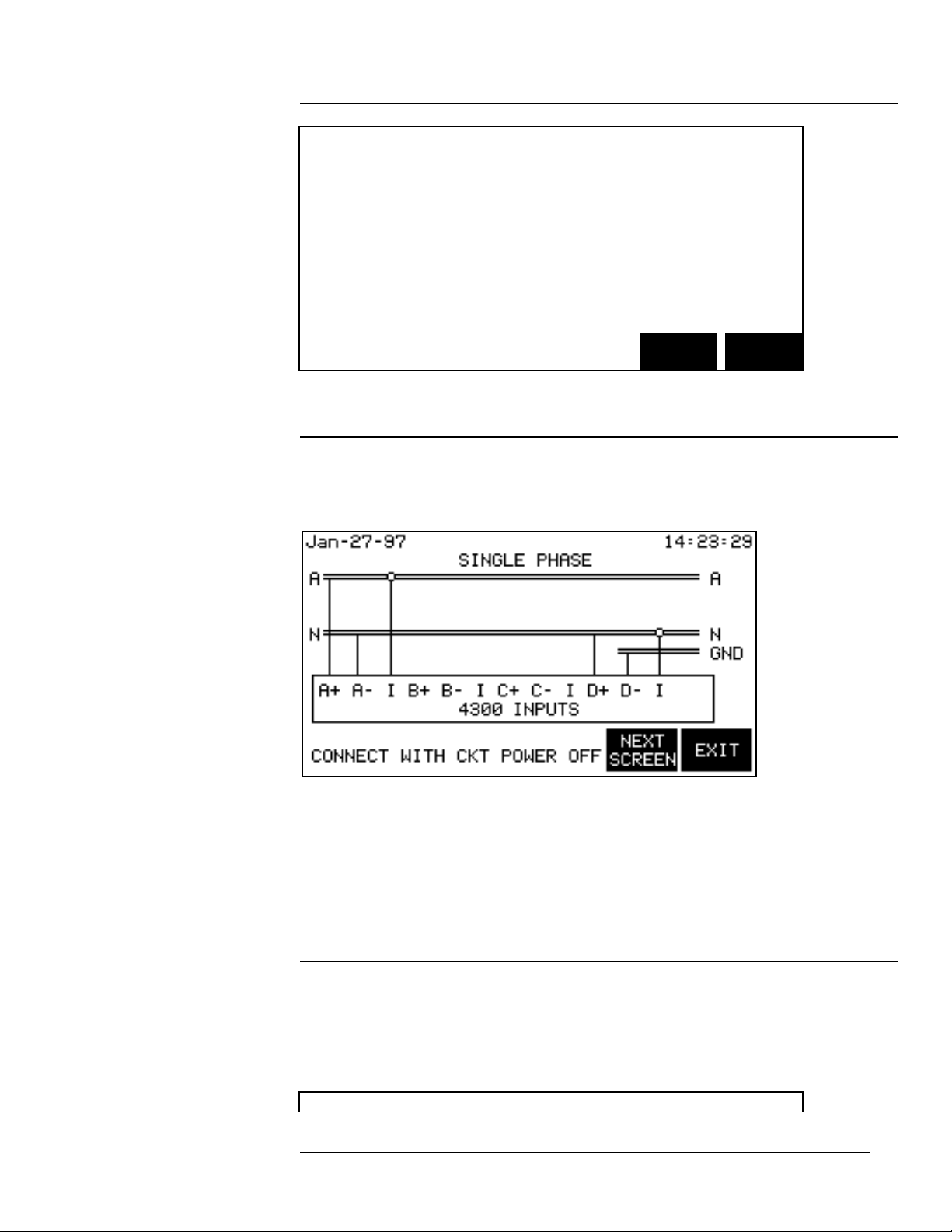
Step 4 Press the NEXT SCREEN SOFTKey. A circuit diagram will be
displayed showing how to connect the voltage and current probes for the
circuit type previously selected.
The purpose of this screen is to enable users to verify that all probes have
been connected properly. If not connected properly, power OFF the
PP4300 immediately. Make any necessary changes to the connections,
and start the tour over again at 5.3 Power ON the PP4300.
Step 5 Press the NEXT SCREEN SOFTKey.
The “Current Probes” screen will be displayed.
Jan-17-97 18:34:45
Page
27
Page 46
Chapter 5 Easy Start Tour
TASK 808
CURRENT PROBES
CHANNEL PROBE TYPE
A TR2500
B TR2500
C TR2500
D TR2500
NEXT NEXT NEXT
CHAN PROBE SCREEN CANCEL
Use the NEXT CHAN SOFTKey to highlight channels and the NEXT
PROBE SOFTKey to toggle through the available current probe types.
Specify the probe type for each channel to be monitored (or NONE if the
channel will not be monitored). Press the NEXT SCREEN SOFTKey
when finished with the “Current Probes” screen.
Jan-17-97 18:34:45
ENTER SITE/FILE NAME
PRESENT SITE/FILE NAME:
CHILLER
NOTE: THE SITE/FILE NAME WILL BE
USED TO NAME FILES STORED ON THE
MEMORY CARD.
ENTER NEXT
NAME SCREEN CANCEL
Step 6 Press the ENTER NAME SOFTKey to display the alphabetic
entry screen for entry of the site/file name (or press the NEXT SCREEN
SOFTKey if the site/file name already exists and is OK).
Page 28
Page 47
Chapter 5 Easy Start Tour
TASK 808
NOTE - The site/file name is important for two reasons: 1) it identifies the
site where the data was collected, and 2) it becomes the name of the file
created when the data is saved. Although up to 20 characters may be
used in the name, only the first eight will be used for the file name.
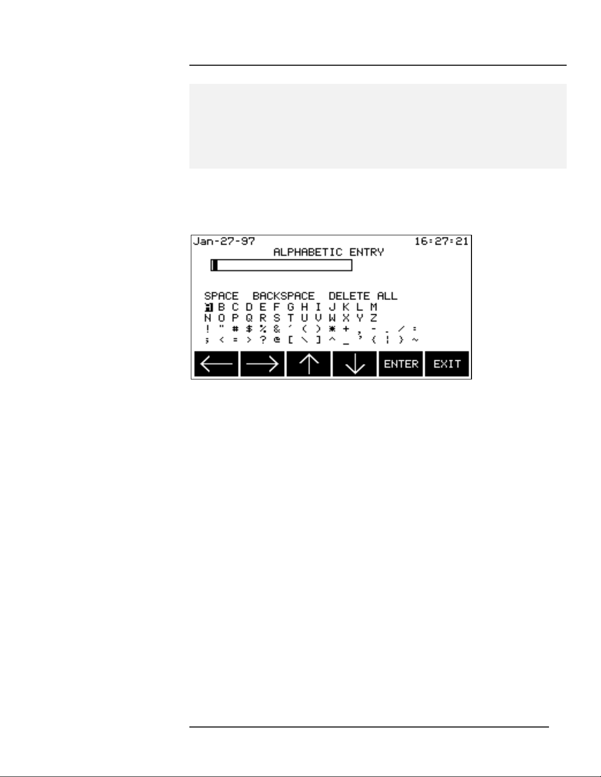
Use the special alphabetic data entry screen shown below to enter the
site/file name:
The arrow SOFTKeys are used to highlight desired letters. The ENTER
SOFTKey moves highlighted letters into the small text window at the top of
the display area until the site/file name is completed. Use the numeric
keypad for numbers.
Press the EXIT SOFTKey when finished. The “Enter Site/File Name”
screen will be displayed again.
Press the NEXT SCREEN SOFTKey to continue:
Page
29
Page 48
Chapter 5 Easy Start Tour
TASK 808
Jan-17-96 18:34:45
CLEAR EVENT MEMORY & START MONITORING
- IF CLEAR IS PRESSED, ALL DATA
PRESENTLY IN MEMORY WILL BE ERASED.
- IF ADD IS PRESSED, NEW DATA WILL
BE ADDED TO WHAT IS ALREADY STORED
IN MEMORY.
CLEAR ADD CANCEL
Step 7 Press one of the following SOFTKeys:
CLEAR to clear memory and start collecting event data.
ADD to add new events to those already stored in
memory.
CANCEL to quit without changing anything.
If CLEAR or ADD is selected, circuit monitoring will begin. The “Easy
Start Summary” screen will be displayed, summarizing the configuration
which has just been defined:
Jan-17-96 18:34:45
EASY START SUMMARY
CIRCUIT TYPE: 3 PHASE DELTA
PROBES:
CHAN A TR2500 CHAN B TR2500
CHAN C TR2500 CHAN D NONE
SITE NAME: CHILLER
DATABASE: CLEAR
** PRESS OK TO ACCEPT SETTINGS
** PRESS CANCEL TO DISREGARD SETTINGS
OK CANCEL
Step 8 Complete the EASY START configuration process by pressing
either the OK or the CANCEL SOFTKey:
Page 30
Page 49
Chapter 5 Easy Start Tour
TASK 808
If the
configuration is… Then…
OK Press the OK SOFTKey to save the
configuration.
Not OK Press the CANCEL SOFTKey to quit or start the
EASY START process over again from the
beginning (without saving the configuration
settings). The “Scope Mode” screen will be
displayed.
5.5 Viewing Data/Reports
Once monitoring is ON and data is being collected, user interest naturally
shifts from monitoring the data to viewing the data.
A wealth of viewing options and data formats is available from the “Scope
Mode” screen to display the data being collected, including:
o The “Scope Mode” waveform
o The “Meter Mode” data display
o The “Harmonics” graphic and text displays
o The four reporting options from the “View Data” menu
5.5.1 Viewing Scope Mode
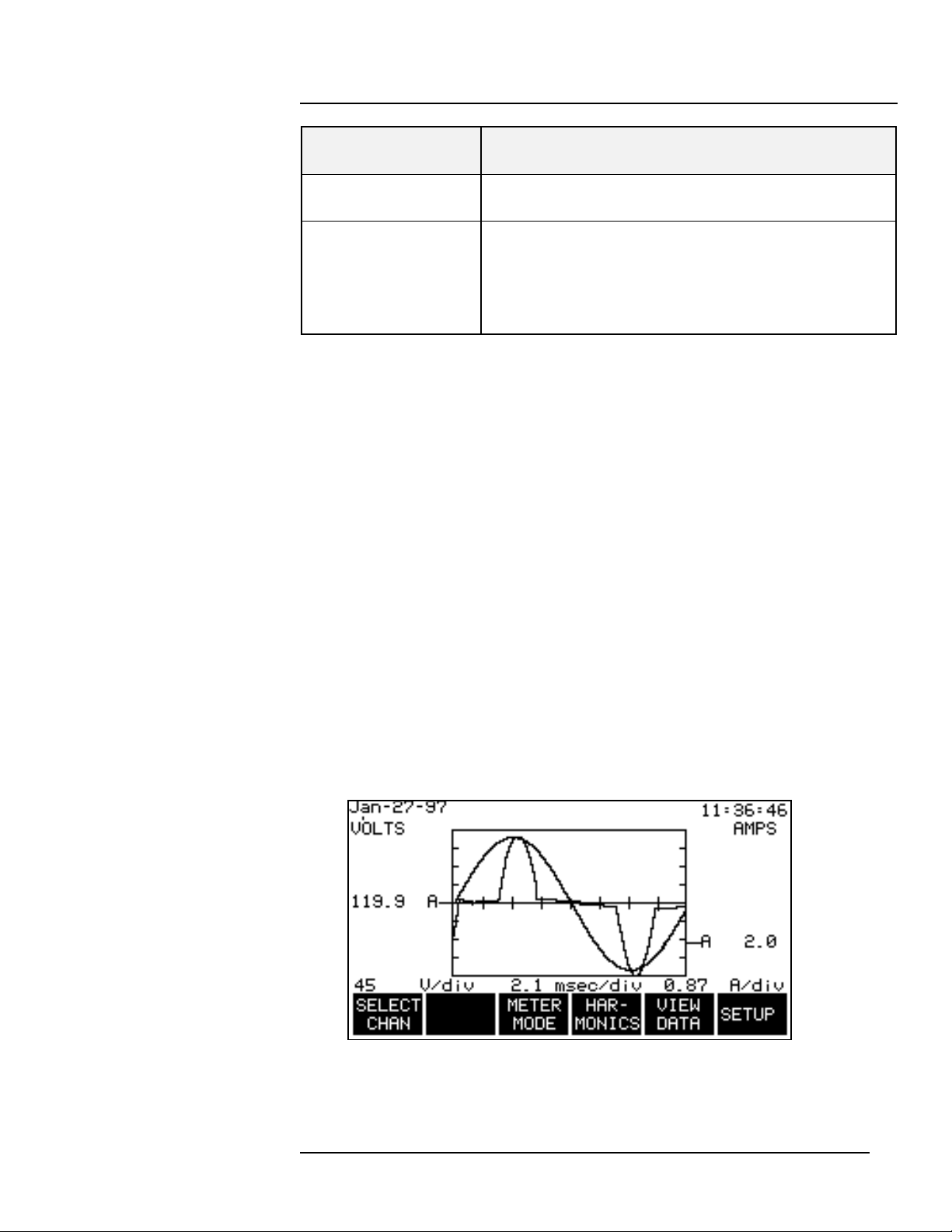
The “Scope Mode” screen functions as a power oscilloscope and displays
real-time voltage and current waveforms for all eight channels. The display
is dynamically updated every two or three seconds.
Page
31
Page 50
Chapter 5 Easy Start Tour
TASK 808
NOTE - At this point, the graph may appear cluttered if data from all eight
channels is being displayed. Unwanted data may be filtered out at any
time by turning each channel’s volts and amps OFF using the “Channel
Selection” screen (shown in Step 1 below).
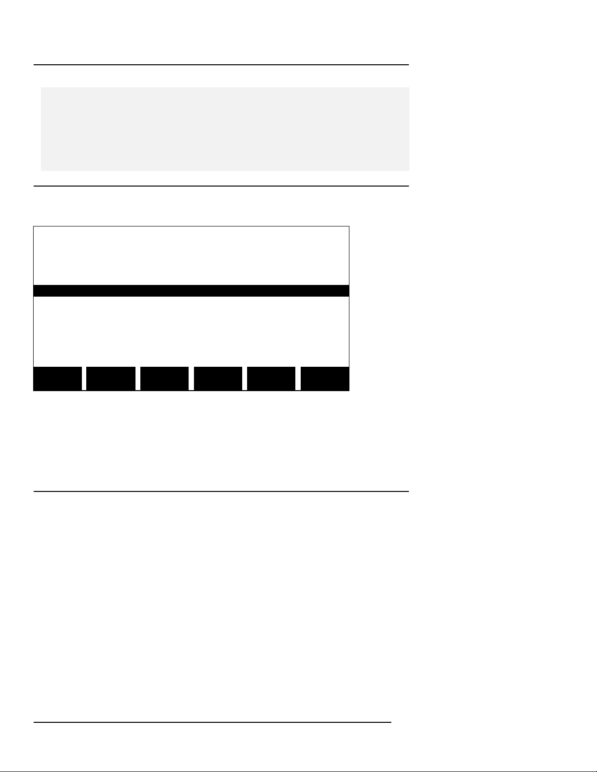
Step 1 Press the SELECT CHAN SOFTKey to access the “Channel
Selection” screen.
Jan-17-96 18:34:45
CHANNEL SELECTION
CHANNEL VOLTS AMPS
A ON ON
B OFF OFF
C OFF OFF
D OFF OFF
NEXT VOLTS AMPS
CHAN ON/OFF ON/OFF EXIT
This screen is used to filter data for display on the “Scope Mode” screen.
Toggle volts and amps ON or OFF for each channel as desired. Press the
EXIT SOFTKey to return to the “Scope Mode” screen.
5.5.2 Viewing in Meter Mode
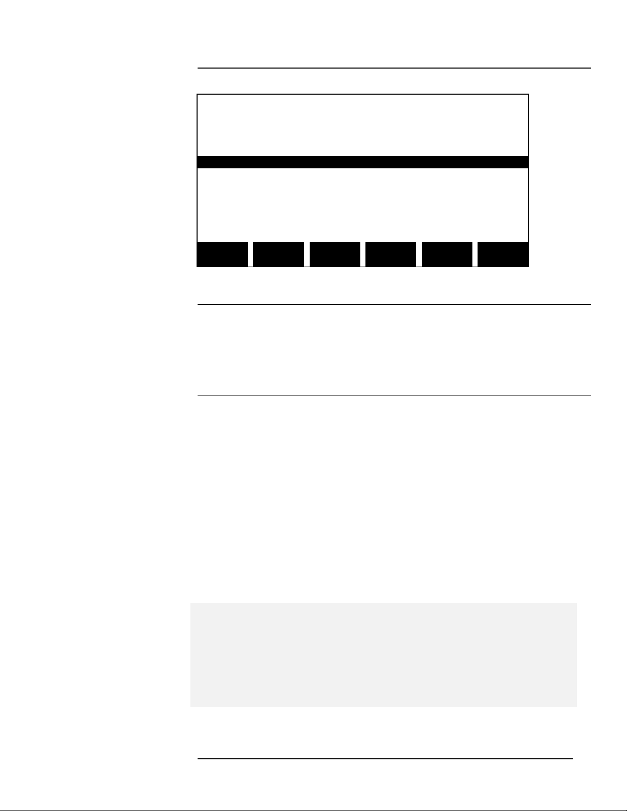
Step 1 From the “Scope Mode” screen, press the METER MODE
SOFTKey to display the first of several “Meter Mode” screens.
Page 32
Page 51
Chapter 5 Easy Start Tour
TASK 808
Jan-17-96 18:34:45
METER MODE
CHAN VOLT AMP WATT VA
A 227.8 9.097 1.800K 2.072K
B 229.0 9.100 1.801K 2.084K
C 228.3 9.146 1.810K 2.088K
D 0.026 0.000 0.000 0.000
ABC 228.3 27.34 5.411K 6.243K
NEXT NEXT CKT
SCREEN METER TYPE EXIT
Step 2 Press the CKT TYPE SOFTKey to verify the “Circuit Type” screen
which displays the currently selected circuit type. If desired, a different
circuit type may be selected. Press the EXIT SOFTKey to return to the
“Meter Mode” screen.
Step 3 Spend a minute, using the NEXT SCREEN, NEXT METER, etc.,
SOFTKeys to navigate through some of the various displays to get a
sense of the different viewing formats which are available in Meter Mode
(a detailed explanation of Meter Mode is included in Chapter 7 Reporting
Tour). Press the EXIT SOFTKey to exit the “Meter Mode” and return to the
“Scope Mode” screen.
This completes the Easy Start Guided Tour.
A Footnote on Powering OFF…
NOTE - It is a wise practice to routinely display the “Scope Mode” screen
before powering OFF the PP4300. Powering OFF from other screens
may nullify configuration changes thought to be implemented. In such
cases, the actual configuration, on a subsequent power up, could differ
from the expected configuration.
Page
33
Page 52

Page 53

Chapter 6 Advanced Tour
The Advanced Tour covers the following topics:
6.1 Setup Menu
6.1.2 Set Programmable Features Menu
6.1.4 Memory Functions Menu
6.1.5 Set Input Configurations Menu
Chapter 6 Advanced Tour
TASK 808
Page
35
Page 54
Chapter 6 Advanced Tour
TASK 808
6.1 Setup Menu
6.1.1 Easy Start
In Chapter 5 Easy Start Tour, EASY START was the only setup option
which was explored. However, the Setup Menu contains many other
powerful and important options for configuring the Task 808.
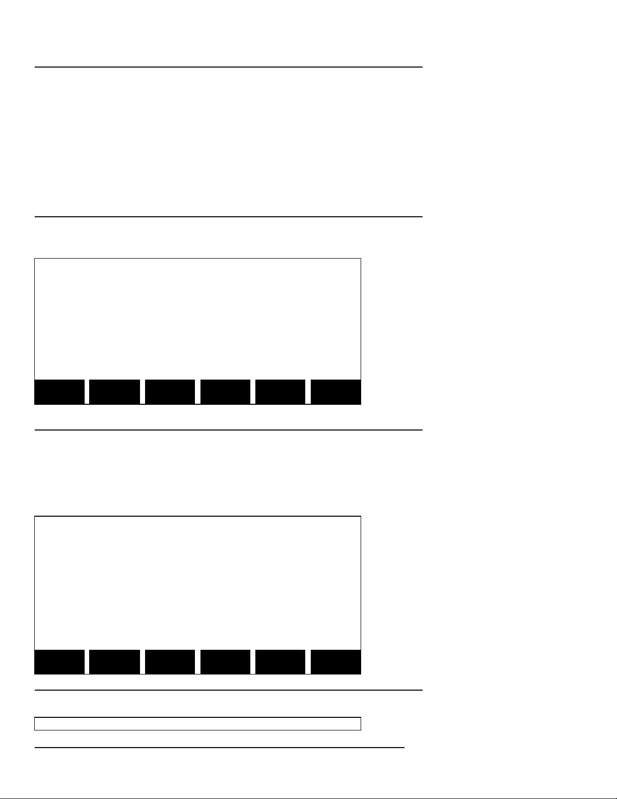
Step 1 From the “Scope Mode” screen, press the SETUP SOFTKey.
Jan-17-97 18:34:45
SETUP MENU
1. EASY START
2. SET PROGRAMMABLE FEATURES
3. TURN MONITORING OFF
4. MEMORY FUNCTIONS
5. SET INPUT CONFIGURATIONS
SCOPE METER HAR- VIEW
MODE MODE MONICS DATA
Step 2 Press the 2 key on the PP4300’s numeric keypad to display the
“Programmable Features” menu.
6.1.2 Set Programmable Features
The following screen/menu will be displayed:
Jan-17-97 18:34:45
SET PROGRAMMABLE FEATURES
1. SET TIME AND DATE
2. ENTER SITE/FILE NAME
3. LCD DISPLAY MODE: NORMAL
4. LCD BACKLIGHT AUTO SHUTOFF:ENABLED
5. AUDIBLE ALARM ON/OFF: ON
EXIT
Step 3 Press the 1 key on the numeric keypad to set time and date:
Jan-17-97 18:34:45
Page 36
Page 55
Chapter 6 Advanced Tour
TASK 808
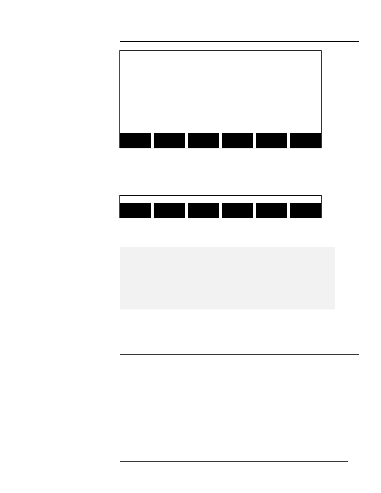
SET TIME AND DATE
PRESENT TIME (hh:mm:ss) = 00:38:04
PRESENT DATE (mm-dd-yy) = Jan-01-97
ENTER ENTER
TIME DATE EXIT
To change the time, press the ENTER TIME SOFTKey; Note that the
SOFTKey options have changed to facilitate setting the time:
BACK
ENTER SPACE EXIT
Use the ENTER and BACKSPACE SOFTKeys, along with the numeric
keypad, to set the correct time and date.
NOTE - It is important that the time (24 hour format) and date is set
correctly because they are used by the system to identify event
data. If changing the time and data becomes necessary, you may
wish to clear event memory as well, since any previously recorded
events will have an incorrect time and date.
When finished, press the EXIT SOFTKey to return to the “Programmable
Features” menu.
Step 4 Option 2 ENTER SITE/FILE NAME was reviewed previously
during the Easy Start Guided Tour.
Press the 3 key on the numeric keypad to toggle the display mode from
NORMAL (blue text and graphics on white background) to INVERTED
(white text and graphics on a blue background). Exit and return to this
menu to see the implemented result.
If Option 4 LCD BACKLIGHT AUTO-SHUTOFF is enabled, the screen will
time out/dim after five minutes has elapsed without any keys being
Page
37
Page 56

Chapter 6 Advanced Tour
TASK 808
pressed. Although pressing any key will restore the screen’s brightness,
the 0 (zero) key is recommended because it is the least likely to affect
anything (unintended exit, changing screens, etc.). Auto-shutoff extends
battery life and its use is recommended.
Option 5 AUDIBLE ALARM, when set to ON, the unit will sound a onesecond beep for each event trigger and a 0.1 second beep for each error
condition.
Press the EXIT SOFTKey again to return to the “Setup Menu” screen.
6.1.3 Turn Monitoring ON/OFF
Press the 3 key on the numeric keypad to toggle monitoring ON and OFF.
Step 5 Press the 4 key on the numeric keypad to display the “Memory
Functions” screen.
6.1.4 Memory Functions
First, a word or two about memory…
Before exploring the memory functions, it is essential that users get a
good conceptual understanding of the Task 808’s data storage and
memory management techniques. For this reason, the Advanced Guided
Tour will take a brief detour at this point.
Page 38
Page 57
Chapter 6 Advanced Tour
TASK 808
Data Storage
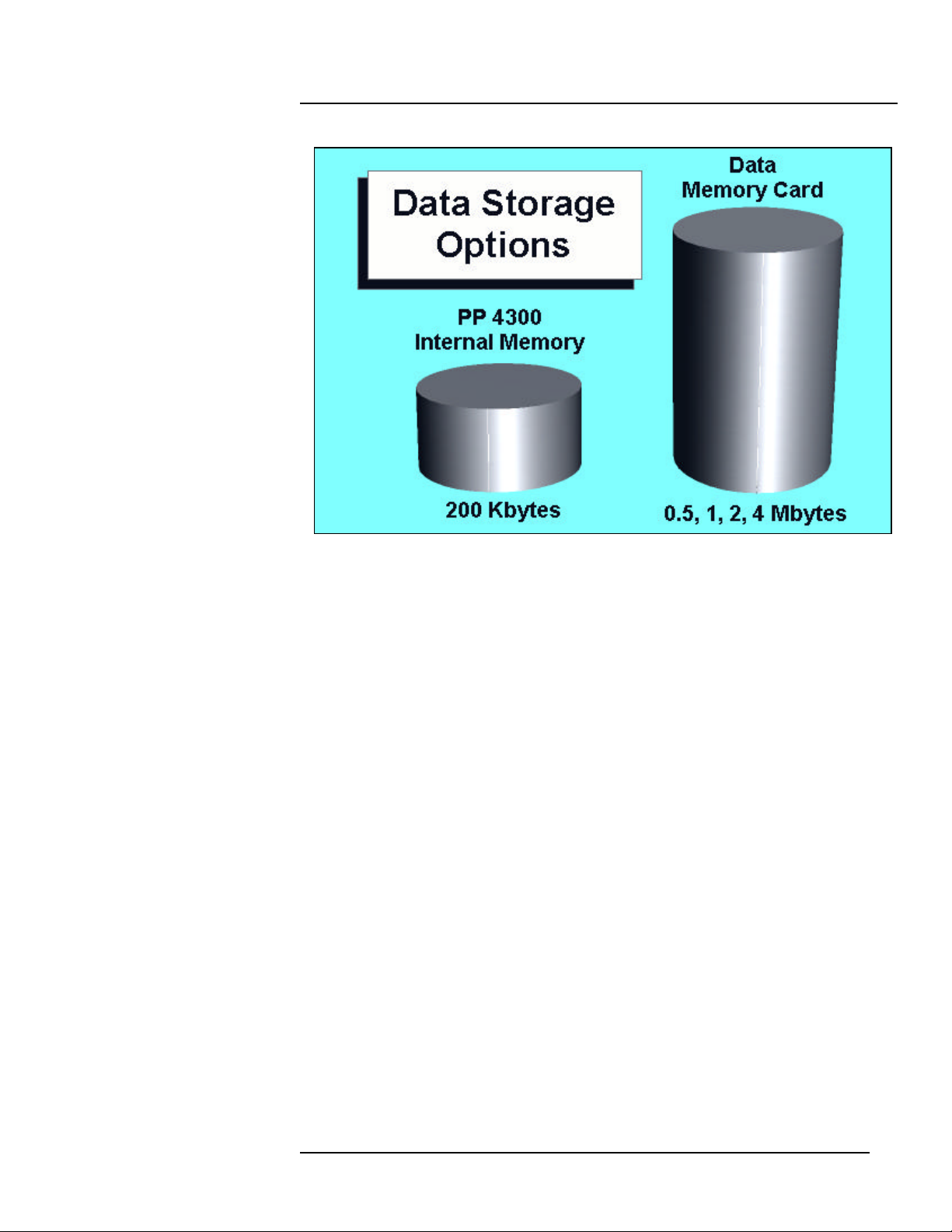
As shown above, the PP4300’s memory (referred to as internal memory)
can store a modest amount of data – about 200 Kbytes (although the
actual memory capacity is 256 Kbytes, overhead cuts the useable data
memory space to about 200 Kbytes).
Saving Data to Internal Memory
If the system is being operated without an optional memory card,
configuration data and monitoring data is automatically saved to the
PP4300’s internal memory . There is no need to “save” the data in the
sense that data must be saved on a PC. The PP4300 automatically writes
data to the internal memory as it is accumulated.
Optional Memory Card
The optional memory card, however, can hold much more data than the
internal memory . Although not an absolute requirement, a memory card is
recommended for almost all applications. Various memory card
capacities are available, see Appendix C.
Auto-transfer
As data is captured, it is always written directly to the PP4300’s internal
memory . If a memory card is included in the configuration, data can be
automatically copied from internal memory to the memory card as the
internal memory fills. This feature is called Auto-transfer.
Page
39
Page 58

Chapter 6 Advanced Tour
TASK 808
Storage Techniques
When data is collected over extended periods of time, it may exceed the
memory capacity of even the memory card. To address this limitation,
data is always written to memory using one of the following user-specified
techniques: either Fill and Stop or Overwrite.
Fill and Stop
This technique works just like it sounds: data is written to internal
memory until it is full and then the data storage process shuts
down. Using this technique, the oldest data is retained, the
collection of data is stopped.
Overwrite
This technique also works just like it sounds: data is written to
internal memory until it is full and then begins to overwrite, starting
with the oldest data first. Using this technique, the most recent data
is retained, the oldest data is overwritten.
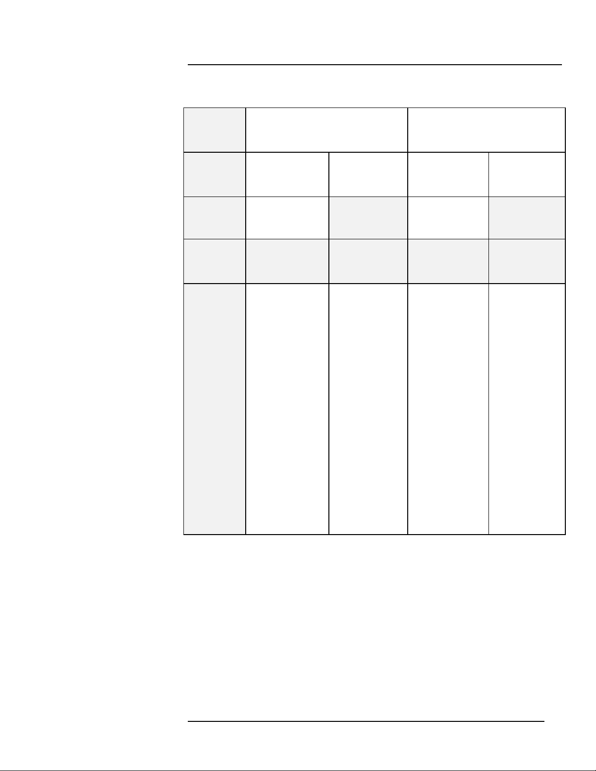
The following table summarizes how these memory features work together
under four different scenarios:
Page 40
Page 59
Memory Feature Table
Memory
mode?
Autotransfer?
Memory
card?
Scenario #1 Scenario #2 Scenario #3 Scenario #4
Fill and Stop Overwrite
Enabled Disabled Enabled Disabled
YES N/A YES N/A
Chapter 6 Advanced Tour
TASK 808
As PP4300’s
R
E
S
U
L
T
Now, back to the Advanced Guided Tour…
internal
memory fills,
data is copied
to the memory
card. When
200 Kbytes of
data has been
copied,
copying stops,
no new data is
recorded.
PP4300’s
internal
memory fills
and stops.
As PP4300’s
internal
memory fills,
data is
copied to the
memory card.
When the
memory card
is full, copying
stops. Internal
memory
continues to
be
overwritten.
NOTE - the
memory card
is never
overwritten.
PP4300’s
internal
memory fills
and is
overwritten.
Page
41
Page 60
Chapter 6 Advanced Tour
TASK 808
Memory Functions, Continued
The “Memory Functions” screen is the function control menu for both the
internal memory and the optional memory card.
Jan-17-97 18:34:45
MEMORY FUNCTIONS
1. MEMORY CARD FUNCTIONS
2. SET AUTO-TRANSFER TO MEMORY CARD
3. CLEAR MEMORY
4. SET MEMORY STORAGE MODE
5. RESET TO FACTORY CONFIGURATION
EXIT
Step 6 Press the 1 key on the numeric keypad to display the Memory
Card Functions screen . This screen displays the status of the memory
card installed. Use this screen to read and write event and setup data on
the memory card and to format the memory card (see Appendix F).
Jan-17-97 18:34:45
MEMORY CARD FUNCTIONS
CARD SIZE: 1024K
CARD FREE SPACE: 10K
WRITE PROTECT:OFF
MEMORY CARD BATTERY:OK
WRITE READ FORMAT
CARD CARD CARD EXIT
Use the View Data menu shown in Chapter 7 to read the Auto-transfer file.
• NOTE: In order to view data stored on a memory card, it must first be
read (copied) into internal memory. Reading data from a memory card
will erase all data presently in internal memory.
Page 42
Page 61

Chapter 6 Advanced Tour
TASK 808
Saving/Reading Data
When data is saved manually to the memory card using the WRITE DATA
SOFTKey, an event file (.evt) is created. This file consists of all data
currently in internal memory. Using the WRITE SETUPS SOFTKey
creates a setup file (.set), which contains the instrument configuration.
When Auto-transfer is enabled, data is saved automatically to the memory
card and is stored in an Auto-transfer file (.mdb). Event files and setup
files are retrieved using the Memory Card Functions screen. Auto-transfer
files are retrieved using the View Data screen.
File Sizes
Since the internal memory data storage capacity is 200 Kbytes, files
written to memory cards manually will always be 200 Kbyte files (even
though the actual amount of data may be less). On the other hand, the size
of files created using the Auto-transfer function is limited only by the size of
the memory card and typically would be much larger than 200 Kbytes. A
procedure has been developed for reading files which were written to the
memory card by auto-transfer and which may be several times larger than
the 200 Kbyte internal memory. In such cases, only 200 Kbytes can be
read into internal memory at a time. Therefore, data is copied from the
memory card to internal memory in 200 Kbyte blocks. The user is
prompted to enter a start date and time. This becomes the starting point
from which the 200 Kbyte block of event data is selected.
Press the EXIT SOFTKey to return to the “Memory Functions” screen.
Step 7 Press the 2 key on the numeric keypad to toggle between Autotransfer enabled, Auto-transfer disabled. As could be seen from the
Memory Features Table (shown earlier), when a memory card is in use, it
is usually wise to enable auto-transfer (scenario #3).
NOTE - If the PP4300 is powered ON with a new or freshly formatted
memory card installed, and with Auto-transfer enabled, it will appear that
much less storage space is available than would be expected. This
phenomenon occurs because auto-transfer automatically allocates space.
Thus, for example, a two Mbyte card will show only 48K of free space. The
actual amount of stored data is shown on the View Data/ “Site Status”
screen.
Page
43
Page 62
Chapter 6 Advanced Tour
TASK 808
Oct-17-96 18:34:45
AUTO-TRANSFER TO MEMORY CARD
AUTO-TRANSFER: ENABLED
ENABL/
DISABL EXIT
Press the EXIT SOFTKey to return to the “Memory Functions” screen.
Step 8 Press the 3 key on the numeric keypad to clear all events stored
in the PP4300’s internal memory .
NOTE - Perform this operation ONLY if there is no valuable information in
internal memory .
Jan-17-97 18:34:45
CLEAR MEMORY
CAUTION!
ALL EVENTS IN INTERNAL MEMORY
WILL BE DELETED.
PRESS EXIT TO ABORT
CLEAR
MEMORY EXIT
Press the EXIT SOFTKey to return to the “Memory Functions” screen
without actually clearing any memory.
Step 9 Press the 4 key on the numeric keypad to toggle between Fill
and Stop and Overwrite using the NEXT MODE SOFTKey.
Jan-17-97 18:34:45
MEMORY STORAGE MODE
Page 44
Page 63
Chapter 6 Advanced Tour
TASK 808
PRESENT MODE: FILL AND STOP
NEXT
MODE EXIT
Press the EXIT SOFTKey to return to the “Memory Functions” screen.
Step 10 Press the 5 key on the numeric keypad to reset parameter
values to the factory configuration, i.e., default settings.
Jan-17-97 18:34:45
RESET TO FACTORY CONFIGURATION
CAUTION!
THIS COMMAND RESETS ALL THRESHOLD
SETTINGS, PROGRAMMABLE FEATURES,
AND INPUT CONFIGURATIONS TO THEIR
FACTORY DEFAULTS.
RESET EXIT
Press the EXIT SOFTKey to return to the “Memory Functions” screen
(without actually resetting to factory configuration).
n Refer to Appendix D PP4300 Technical Specifications for a
complete listing of factory default settings.
Exit from the “Memory Functions” screen and return to the “Setup Menu”
screen by pressing the EXIT SOFTKey.
6.1.5 Set Input Configurations
From the “Setup Menu” screen, press the 5 key on the numeric keypad to
display the “Set Input Configurations” screen.
Several very important parameters are available from the “Set Input
Configurations” screen:
Page
45
Page 64
Chapter 6 Advanced Tour
TASK 808
Oct-17-96 18:34:45
SET INPUT CONFIGURATIONS
1. SET CIRCUIT TYPE
2. SET ACTIVE CHANNELS
3. SET SCALE FACTORS
4. SET SYNC PARAMETERS
5. DEMAND INTERVAL SETTINGS
6. SELECT CURRENT PROBES
7. DEMAND/ENERGY PARAMETER
8. DEMAND AND ENERGY LIMIT
EXIT
Step 1 Press the 1 key on the numeric keypad to set the circuit type. This
screen was previously reviewed in the Easy Start Guided Tour. Exit by
pressing the EXIT SOFTKey.
Step 2 Press the 2 key on the numeric keypad to display the “Active
Channels” screen.
Jan-17-97 18:34:45
ACTIVE CHANNELS
CHANNEL VOLTS AMPS
A ON ON
B ON ON
C ON ON
D LOW ON
NEXT VOLTS AMPS
CHAN ON/OFF ON/OFF EXIT
This screen is used to toggle ON or OFF the status of channels A, B and
C. In addition – if you highlight and toggle channel D, you will notice that
there are three voltage options for channel D: LOW, HIGH and OFF. The
LOW voltage range is from 0.5 to 20.0 Vrms, and is available for channel
D hookups, e.g., ground-to-neutral, which may require a much lower
range. The HIGH voltage range is the same as ON, i.e., from 10 to 600
Vrms. The “ Scale Factors” screen (shown below ) displays the actual
channel D status setting.
Page 46
Page 65
Chapter 6 Advanced Tour
TASK 808
NOTE - The “Active Channels” screen controls the channels which are
actively collecting data. A very similar screen, the “Channel Selection”
screen, was reviewed in the Easy Start Guided Tour. But that screen,
however, only filters the data for display on the “Scope Mode” graph.
Unlike the options on the “Active Channels” screen, the “Channel
Selection” screen has no control over the collection of data.
Exit by pressing the EXIT SOFTKey.
Step 3 Press the 3 key on the numeric keypad to set the voltage and
amperage scale factors for each channel.
Jan-17-97 18:34:45
SCALE FACTORS
CHAN VOLTS AMPS
A 1.0000 1.0000
B 1.0000 1.0000
C 1.0000 1.0000
LOW D 1.0000 1.0000
NEXT ENTER
CHAN SCALE EXIT
The scale factor for all of the listed optional Dranetz-BMI current probes is
automatically factored in behind the scenes and should be entered as 1.0
(unless changed on the secondary of another current transformer).
However, The scale factors of any non-Dranetz-BMI current or voltage
transformer must be accounted for in making accurate measurements.
Because the monitored output current or voltage is frequently stepped
down (divided) from the original current or voltage, this ratio must be
stepped up (multiplied) by the scale factor when computations are
performed.
The scale factor is usually marked on the transformer. This value must be
entered into the “Set Scale Factors” screen. Refer to the device or the
manufacturer’s literature for the scale factor for devices which you may be
using.
Page
47
Page 66

Chapter 6 Advanced Tour
TASK 808
Scale Factor Calculation - Example
Suppose the 5A secondary output current of a 5000A current transformer
is being monitored. The scale factor would be calculated as follows:
CT Full Scale Input x Dranetz-BMI Probe Scale Factor = Scale Factor
CT Full Scale Output
5000 x 1 = Scale Factor of 1000
5
Exit the “Scale Factors” screen by pressing the EXIT SOFTKey.
Step 4 Press the 4 key on the numeric pad to set the sync
(synchronization) parameters. Sync, i.e., maintaining a constant phase
relationship between AC signals, may be either external or internal. When
set to external, the PP4300 attempts to sync to an incoming voltage
signal. When set to internal, the PP4300 uses the nominal frequency when
making measurements. External sync is recommended unless no
adequate voltage source is available.
Enter a nominal frequency which matches the line frequency so that if the
PP4300 loses external sync, it will have a corresponding internal sync.
Failure to set this value correctly can result in erroneous data.
Page 48
Page 67
Chapter 6 Advanced Tour
TASK 808
Jan-17-97 18:34:45
SYNC PARAMETERS
SYNC MODE: EXTERNAL
NOMINAL FREQUENCY: 60.0
SELECT ENTER
SYNC FREQ EXIT
Press the SELECT SYNC SOFTKey to toggle through the sync mode
options. Press the ENTER FREQ SOFTKey to enter the frequency (using
the numeric keypad). Exit by pressing the EXIT SOFTKey.
Step 5 Press the 5 key on the numeric keypad to set the interval, start
time and date for the collection of demand data.
Jan-17-97 18:34:45
DEMAND INTERVAL SETTING
PRESENT INTERVAL: 15 MINUTES
START TIME: 02:02:13
START DATE: Jan-11-96
START OF NEXT INTERVAL: 18:47:13
NOTE: DATA WILL FILL A CLEARED MEMORY
BUFFER IN 6 DAYS ASSUMING NO OTHER
EVENTS OCCUR.
SET START START
INTRVL NOW AT EXIT
Press the SET INTRVL SOFTKey to change the interval start time and
date (watch the screen carefully when selecting this – especially the
SOFTKeys -- note that ENTER and BACKSPACE SOFTKeys become
operational).
This screen is especially significant because it calculates how long it will
take to fill the internal memory excluding events other than timed demand
interval events.
Page
49
Page 68
Chapter 6 Advanced Tour
TASK 808
When finished, press the START NOW SOFTKey to start collecting
immediately, or use the START AT SOFTKey to enter a different (and
future) start time and date. When finished, the “Set Input Configuration”
screen will be displayed.
Step 6 Press the 6 key on the numeric keypad to select current probes
(this function was already reviewed in the Easy Start Guided Tour). After
making selection, exit by pressing the EXIT SOFTKey.
Step 7 Press the 7 key on the numeric keypad to set the demand/energy
parameter.
Jan-17-97 18:34:45
DEMAND/ENERGY PARAMETER
PARAMETER: WATTS
WATTS VA VARS EXIT
Press the WATTS, VA or VARS SOFTKeys to set the demand/energy
parameter. Exit by pressing the EXIT SOFTKey.
Page 50
Page 69
Chapter 6 Advanced Tour
TASK 808
Step 8 Press the 8 key on the numeric keypad to enable and set demand
and energy limits:
Jan-17-97 18:34:45
DEMAND/ENERGY LIMITS
DEMAND LIMIT : 2229.0 W
ENERGY RATE LIMIT : 9300.0 WHR
SET SET DISABLE DISABLE
DEMAND ENERGY DEMAND ENERGY EXIT
Use the SOFTKeys to SET, ENABLE or DISABLE the limits. The
consequences of enabling and setting these limits are as follows:
Demand limit - At the end of each demand interval, the average demand
is compared with this limit. If the demand is greater than this limit, it is
treated as an event and is recorded.
Energy Rate Limit - The energy rate is computed once every minute. If the
rate exceeds this limit, it is treated as an event and is recorded.
Exit by pressing the EXIT SOFTKey.
Exit from the “Set Input Configurations” screen by pressing the EXIT
SOFTKey.
Exit from the “Setup Menu” screen and return to the “Scope Mode” screen
by pressing the SCOPE MODE SOFTKey.
This completes the Advanced Guided Tour.
Page
51
Page 70

Page 71

Chapter 7 Reporting Tour
Chapter 7 Reporting Tour
The Reporting Tour covers the following topics:
7.1 View Data
7.2 Meter Mode
7.3 Viewing Harmonics (model 808/H-M only)
7.4 Screen Printing
TASK 808
Page
53
Page 72
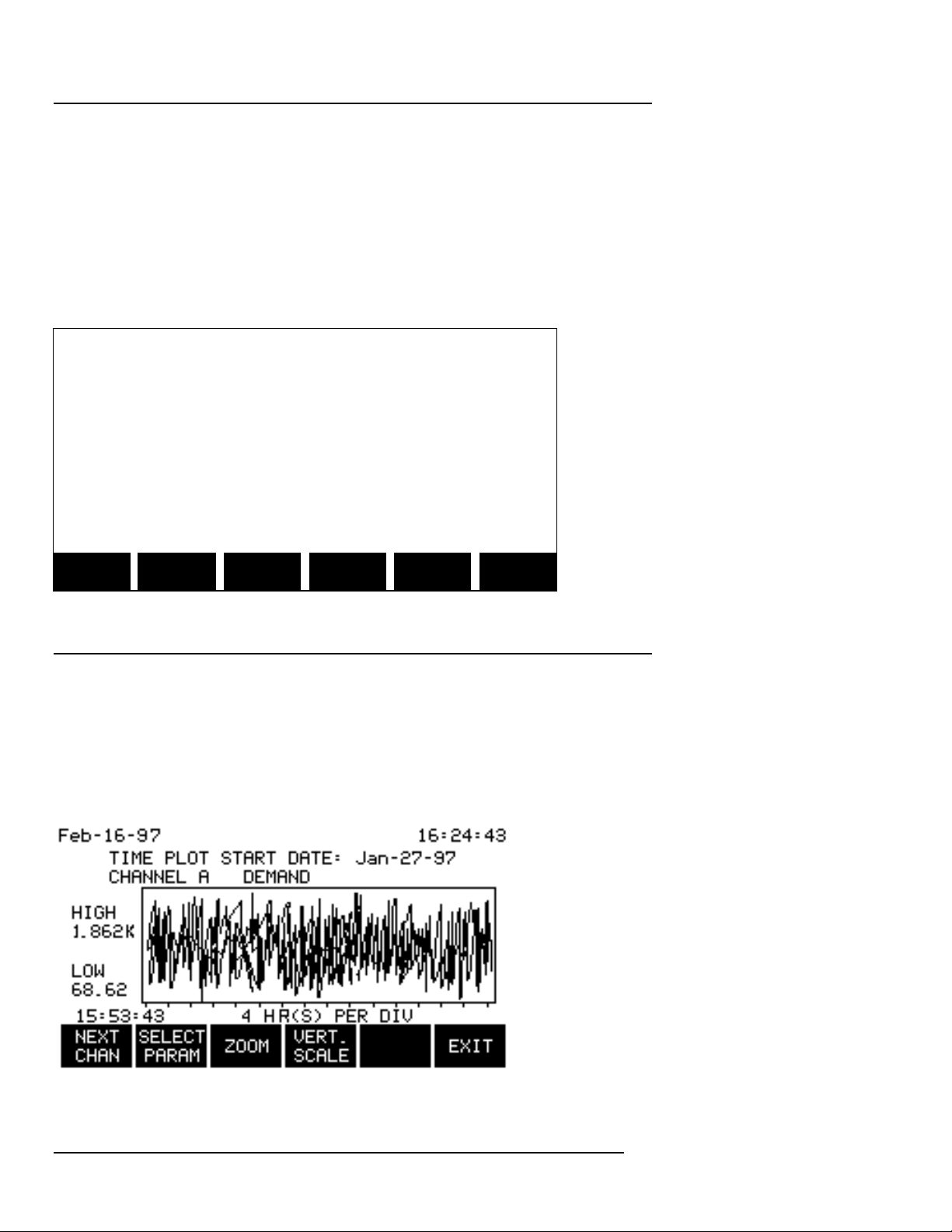
Chapter 7 Reporting Tour
TASK 808
7.1 View Data
The “View Data” menu provides access to graphic displays, reports and
the Auto-transfer files.
From the “Scope Mode” screen, press the VIEW DATA SOFTKey:
Jan-17-97 18:34:45
VIEW DATA MENU
1. TIME PLOT
2. DEMAND REPORT
3. ENERGY REPORT
4. MIN/MAX REPORT
5. READ DATA FROM MEMORY CARD
6. SITE AND 4300 STATUS
SCOPE METER
MODE MODE SETUP
Step 1 From the “View Data” screen, press the 1 key to display the first of
the Time Plot graphs.
Definition
A time plot is a graph of a single parameter value, for a single channel,
over time. The curve consists of timed events and is redrawn every ten
seconds.
Page 54
Page 73
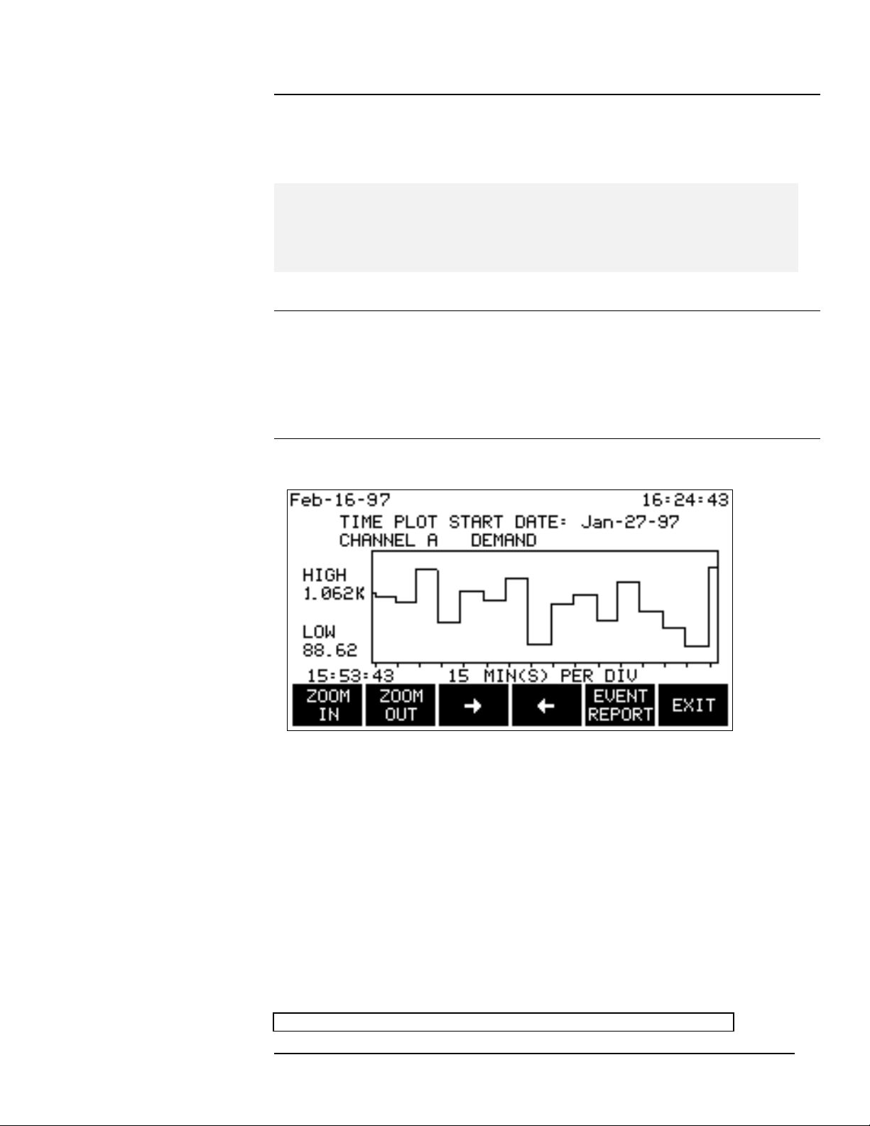
Chapter 7 Reporting Tour
TASK 808
Even though a time plot may cover an extended period of time, it is
possible to analyze the data in great detail.
NOTE - START DATE is displayed across the top of the “Time Plot ”
screen. This is the date on which the time plot data collection started.
Step 2 Select the channel and parameter to be analyzed: Press the
NEXT CHAN SOFTKey to page through the channels. Press the
SELECT PARAM SOFTKey to change parameters, by highlighting and
selecting the desired parameter from a list.
Step 3 Press the ZOOM SOFTKey to begin the analysis.
Select an Area of Interest
Use the arrow SOFTKeys to move right and left side brackets inward from
the edge of the screen toward the area of interest, until it is bracketed on
either side. Then press the ZOOM IN SOFTKey. Repeat this process, if
necessary, until the exact area of interest has been selected.
Then press the EVENT REPORT SOFTKey to display a listing of events,
including the date, time and event description for each:
Jan-17-97 18:34:45
Page
55
Page 74
Chapter 7 Reporting Tour
TASK 808
EVENT REPORT
DATE TIME DESCRIPTION
01-13 10:23 Dmd Int-1.800KW PF 0.86
01-13 10:31 Dmd Int-1.801KW PF 0.86
01-13 10:39 MONITOR OFF
01-13 10:43 MONITOR ON
01-13 10:44 Dmd Int-1.790KW PF 0.86
01-13 10:51 Dmd Int-1.802KW PF 0.86
01-13 10:59 DATABASE FULL
01-13 10:07 Dmd Int-1.806KW PF 0.86
NEXT PAGE PAGE
EVENT DOWN UP DETAIL EXIT
Seven new Task 808-specific event types have been created:
Event Report Abbreviation Full Description
DEMAND CONFIG demand interval setting and
parameter change
THRESH CONFIG energy /demand user-defined
threshold change
PROBE CONFIG current probe change
Dmd Int demand interval change
Dmd Lim demand threshold crossing
Energy Rate Lmt energy rate threshold crossing
MIDNIGHT SUMMARY midnight summary
In addition, each time data in the internal memory is overwritten, an event
named “Database Full” is added to the event list.
Step 4 Using the PAGE DOWN, PAGE UP and NEXT EVENT
SOFTKeys, locate and highlight the specific event of interest. Then press
the DETAIL SOFTKey. The “Demand Interval Report” screen will be
displayed:
Page 56
Page 75
Chapter 7 Reporting Tour
TASK 808
Jan-17-97 18:34:45
DEMAND INTERVAL REPORT
(DEMAND INTERVAL EVENT)
EVENT DATE AND TIME :Jan-14-97 20:05:37
DEMAND : 1.806KW
INTERVAL ENERGY : 376.6 W-HR
DAILY ENERGY : 15.23K W-HR
MONTHLY ENERGY : 47.80K W-HR
PF : 0.86
DAILY MONTH
PEAK PEAK STATUS ENERGY EXIT
The “Demand Interval Report” screen also provides a gateway to four
additional screens, as illustrated below.
Daily Peak/Monthly Peak Reports
These reports have the same format: The Daily Peak contains the four
highest peak readings for the day; the Monthly Peak report contains the
four highest peak readings for the month.
Jan-17-97 18:34:45
CHANNEL ABC PEAK DEMAND REPORT
(DEMAND INTERVAL EVENT)
DAILY PEAK DEMAND: Jan-17-97
TIME W PF
14:06 41.46K 1.000
13:36 41.35K 1.000
13:21 41.29K 1.000
10:02 41.22K 1.000
INTRVL MONTH
DATA PEAK STATUS ENERGY EXIT
Status
The status report format is the same as that of the Meter Mode # 1 report,
except that it does not dynamically update. It is a snapshot taken at the
time of the event.
Energy
This report provides a snapshot of the energy data for the demand interval
event selected.
Jan-17-97 18:34:45
CHANNEL ABC ENERGY REPORT
Page
57
Page 76
Chapter 7 Reporting Tour
TASK 808
(DEMAND INTERVAL EVENT)
ENERGY RATE: 687.2 W-MN
DAILY: Jan-13-97 99.29K W-HR
MONTHLY: Jan-97 99.29K W-HR
DAYS INTO BILLING PERIOD: 23
INTRVL DAILY MONTH
DATA PEAK PEAK STATUS EXIT
Press the EXIT SOFTKey four times to return to the “View Data” menu.
Step 5 Press the 2 key on the numeric keypad to display the demand
report. The content of this report is determined by parameters previously
set using options from the “Set Input Configurations” screen.
Oct-17-96 18:34:45
CHANNEL ABC PEAK DEMAND REPORT
PRESENT INTERVAL DATA
PRESENT DEMAND: 41.45K W
PROJECTED DEMAND: 41.40K W
10 MINUTES INTO 15 MINUTE INTERVAL
DAILY MONTH EVENT
PEAK PEAK DATA EXIT
Press EXIT to return to the “View Data” menu.
Page 58
Page 77
Chapter 7 Reporting Tour
TASK 808
Step 6 Press the 3 key on the numeric pad to display the “Energy” report.
A format similar to one shown earlier will be displayed. However, this
report is a summary report and is dynamically updated.
Jan-17-97 18:34:45
CHANNEL ABC ENERGY REPORT
ENERGY RATE: 687.2 W-MN
DAILY: Jan-13-97 99.29K W-HR
MONTHLY: Jan-97 99.29K W-HR
DAYS INTO BILLING PERIOD: 23
EVENT
DATA EXIT
Press the EVENT DATA SOFTKey to display the following menu:
Jan-17-97 18:34:45
EVENT DATA MENU
1. DEMAND INTERVALS
2. LIMIT CROSSINGS
3. MIDNIGHT SUMMARY
4. ALL EVENTS
EXIT
Display the “Demand Interval” (Event) report by pressing the 1 key on the
numeric keypad. This report filters out all events except demand interval
events. Press EXIT to return to the “Event Data Menu” screen
Detail (Daily Peak, Monthly peak , Status and Energy) is available for the
selected event. Press EXIT to return to the “Event Data Menu” screen
Press the 2 key on the numeric keypad to display another filtered version
– the “Limit Crossings” screen (Demand Limit and Energy Rate Limit ), if
any crossings exist.
Step 7 Press the 3 key on the numeric keypad to display a listing of the
“Midnight Summary ” reports available.
Page
59
Page 78
Chapter 7 Reporting Tour
TASK 808
NOTE - The “Midnight Summary ” reports are created automatically
each night but displayed only on request.
Jan-17-97 18:34:45
EVENT REPORT
DATE TIME DESCRIPTION
01-13 00:00 MIDNIGHT SUMMARY
01-14 00:00 MIDNIGHT SUMMARY
01-15 00:00 MIDNIGHT SUMMARY
01-16 00:00 MIDNIGHT SUMMARY
NEXT PAGE PAGE
EVENT DOWN UP DETAIL EXIT
Use the highlight bar to select a date – then press the DETAIL SOFTKey
to display the Daily Peak Demand.
Press the 4 key on the numeric keypad to display ALL, i.e., the unfiltered
event report (illustrated previously).
Step 8 Press the EXIT SOFTKey to return to the “View Data” menu.
Press the 4 key on the numeric keypad to display the Min/Max report. This
report displays daily, weekly and monthly Min/Max data by each channel
and by nine parameters:
Page 60
Page 79
Chapter 7 Reporting Tour
TASK 808
Jan-17-97 18:34:45
MIN MAX REPORT FOR CHANNEL: A
PERIOD DATE TIME VOLTS
DAILY MIN. Jan-17-97 10:25 100.0
DAILY MAX. Jan-17-97 18:00 118.0
WEEKLY MIN. Jan-10-97 20:25 86.66
WEEKLY MAX. Jan-13-97 14:04 119.9
MONTHLY MIN.Jan-10-97 20:25 86.66
MONTHLY MAX.Jan-13-97 14:04 119.9
NEXT NEXT
CHAN PARAM EXIT
NOTE - Week and month periods are calendar week (Sun-Sat) and
month.
Reading the Auto-transfer file from the memory card
o Exit to the “View Data” menu.
o Insert the memory card containing the data to be read.
o Press the 5 key on the numeric keypad to display the Read Events
From Memory Card screen:
Jan-17-97 18:34:45
READ EVENTS FROM MEMORY CARD
CAUTION!
EVENTS PRESENTLY IN MEMORY WILL BE
DELETED WHEN EVENTS FROM THE CARD
ARE COPIED INTO MEMORY.
PRESS EXIT TO CANCEL OR
PRESS TRANSFER TO CONTINUE
TRANS-
FER EXIT
o Observe the caution. Press the TRANSFER SOFTKey. The “View
Events by Date and Time” screen is displayed.
o Enter the starting date and time of the desired events to be transferred
(not necessarily the default date and time, which is the oldest event
date and time).
Page
61
Page 80
Chapter 7 Reporting Tour
TASK 808
o To enter the date, Press the START DATE SOFTKey. Use the
numeric keypad to enter the two digit month, then press the ENTER
SOFTKey. Repeat this process for day, year, hour, minute, etc.
o Press the READ EVENTS SOFTKey to begin reading data.
NOTE - If the memory card contains more data than can fit into the
internal memory, only as much data as possible will be transferred. After
viewing the initial batch of data, note the date and time of the last event.
Enter these values into the START DATE/TIME screen to read the
remaining data.
Site and 4300 Status
Step 9 Press the 6 key on the numeric keypad to display the “Site Status”
screen:
Jan-17-97 18:34:45
SITE STATUS
SITE NAME: CHILLER
START: 14 Jan 97, 12:22:46
VOLTAGE CHANNELS ON: A, D
CURRENT CHANNELS ON: A, D
DATABASE: 50% FULL
AUTO-TRANSFER FILE: 14% FULL
4300 SELF
STATUS TEST EXIT
This screen also provides a gateway to two additional screens:
4300 STATUS
Jan-17-97 18:34:45
4300 STATUS
INPUT: GOOD
MEMORY: 512K GOOD
HOST CPU: V 1.0
ACP CPU: V 1.0
DATABASE: V 1.0
TASKCARD: TASK 808, EHM
Page 62
EXIT
Page 81
Chapter 7 Reporting Tour
TASK 808
NOTE - “GOOD Input” means the current and voltage measurements are
OK and within range limits. The memory test results are the results of the
test performed during power ON and if the result is not GOOD, call
Dranetz-BMI Customer Service.
V 1.0 is an abbreviation for Version 1.0.
EHM is an abbreviation for Energy/Harmonics/Memory .
Self Test
The self test performs a non-destructive test of the internal memory ,
although the test will interrupt data collection.
Jan-17-97 18:34:45
RUN SELF TEST
CAUTION!
LOSS OF DATA WILL RESULT IF THIS TEST
IS SELECTED DURING DATA ACQUISITION.
RUN TEST DURING NON-CRITICAL
MONITORING TIMES ONLY.
PRESS BEGIN TEST TO CONTINUE
PRESS EXIT TO ABORT
BEGIN
TEST EXIT
The reason behind this warning is that the Self Test turns monitoring OFF
during the test, then turns it back ON when the test is finished (unless it
was already OFF when the test was begun).
Press the BEGIN TEST SOFTKey to start the self test.
Page
63
Page 82
Chapter 7 Reporting Tour
TASK 808
7.2 Meter Mode
The Meter Mode consists of four different “meters,” or formats, updating in
real time. These meters present the monitored data across 35 different
screens. Don’t let this number be intimidating, however, because paging
through this array of information can be accomplished quickly and easily.
Navigation
Navigation through these various displays is performed using one or more
of four navigation SOFTKeys:
NEXT METER
NEXT SCREEN
NEXT CHAN
NEXT PARAM
Meter Mode consists of the following screen configuration, in meter
sequence, starting with meter #1:
Meter # 1 - This meter provides a spreadsheet display of values for all 11
parameters for all four channels plus ABC. Three screens are required to
display values for all 11 parameters.
Use the NEXT SCREEN
SOFTKey to page from
screen to screen.
Jan-17-97 18:34:45
METER MODE
CHAN VOLT AMP WATT VA
A 117.4 0.743 -5.927 87.26
B 0.879 2.091 1.554 1.839
C 1.001 2.000 1.765 2.003
D 2.316 1.264 0.866 2.929
ABC 117.4 0.743 -5.927 87.26
NEXT NEXT CKT
SCREEN METER TYPE EXIT
Page 64
Page 83
Chapter 7 Reporting Tour
TASK 808
Meter # 2 - This meter emulates a digital volt meter (DVM), displaying all
11 parameter values for each of four channels plus ABC. Three screens
each are required to display the values for the 4 channels plus ABC.
A B C D ABC
Use NEXT CHAN to change channels, NEXT SCREEN to page
through parameters.
Jan-17-97 18:34:45
CHANNEL: A
114.5 V
1.368 I
143.6 KW
156.7 KVA
NEXT NEXT NEXT CKT
CHAN SCREEN METER TYPE EXIT
Page
65
Page 84
Chapter 7 Reporting Tour
TASK 808
Meter # 3 - This meter emulates a digital volt meter (DVM), displaying a
single parameter value for four channels plus ABC. 11 screens are
required to display the values for all of the parameters.
Use NEXT PARAM to page through
the 11 parameters.
Jan-17-97 18:34:45
VOLTS
A: 114.5
B: 1.368
C: 143.6
D: 156.7
ABC: 115.8
NEXT PREV NEXT CKT
PARAM PARAM METER TYPE EXIT
Page 66
Page 85
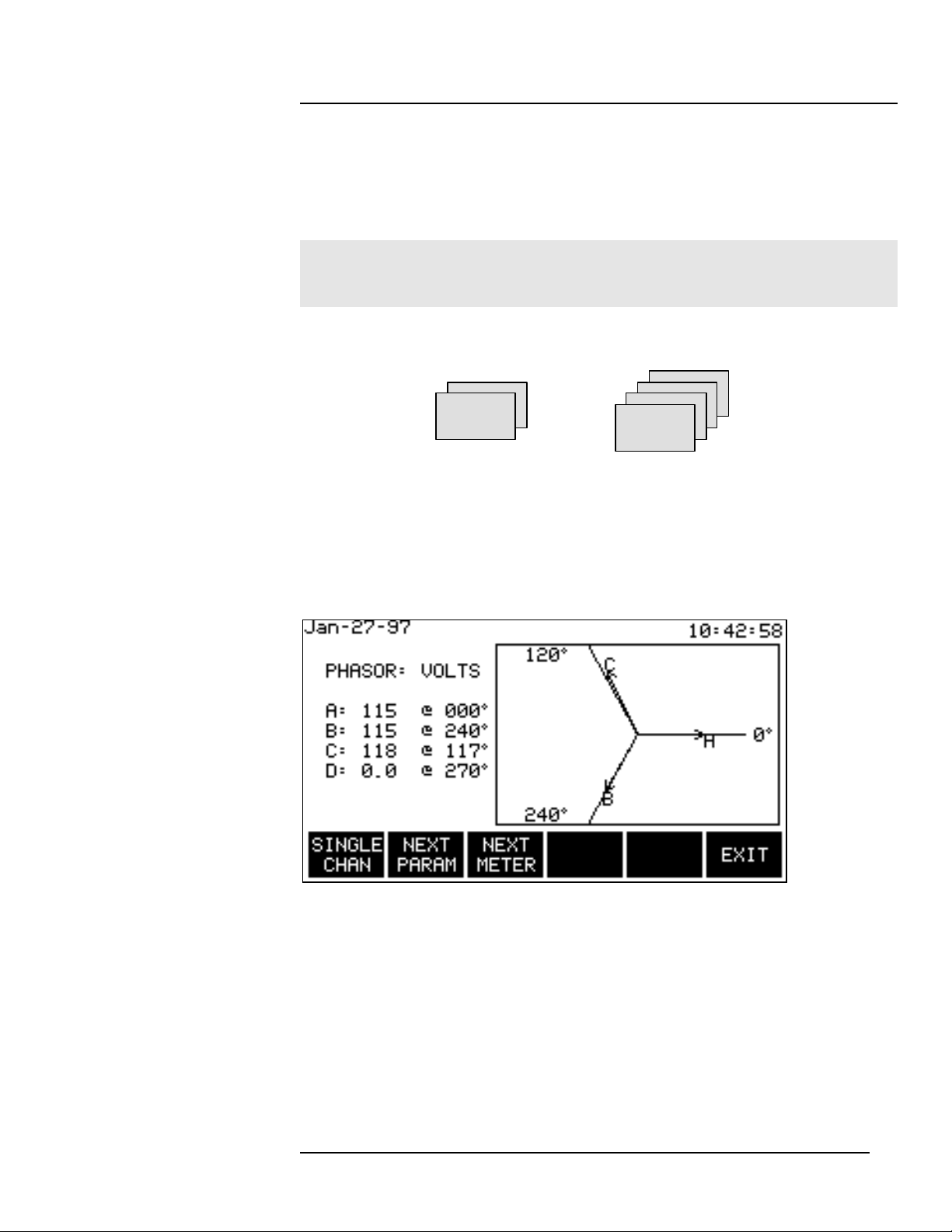
Chapter 7 Reporting Tour
TASK 808
Meter # 4 - This meter is a graphical phase meter displaying the phase
angle for either a volts-only or amps-only phasor for all four channels. In
addition, volts and amps phasors are available for each of the four
channels.
NOTE - Channels with values below 10% of the maximum channel value
will not be displayed.
Six screens are required to display the phasors.
Use SINGLE
Use CHAN to switch
NEXT PARAM to combined
to toggle between VOLTs and AMPs phasors,
VOLTs and AMPs then use NEXT CHAN to
screens page through channels
Page
67
Page 86
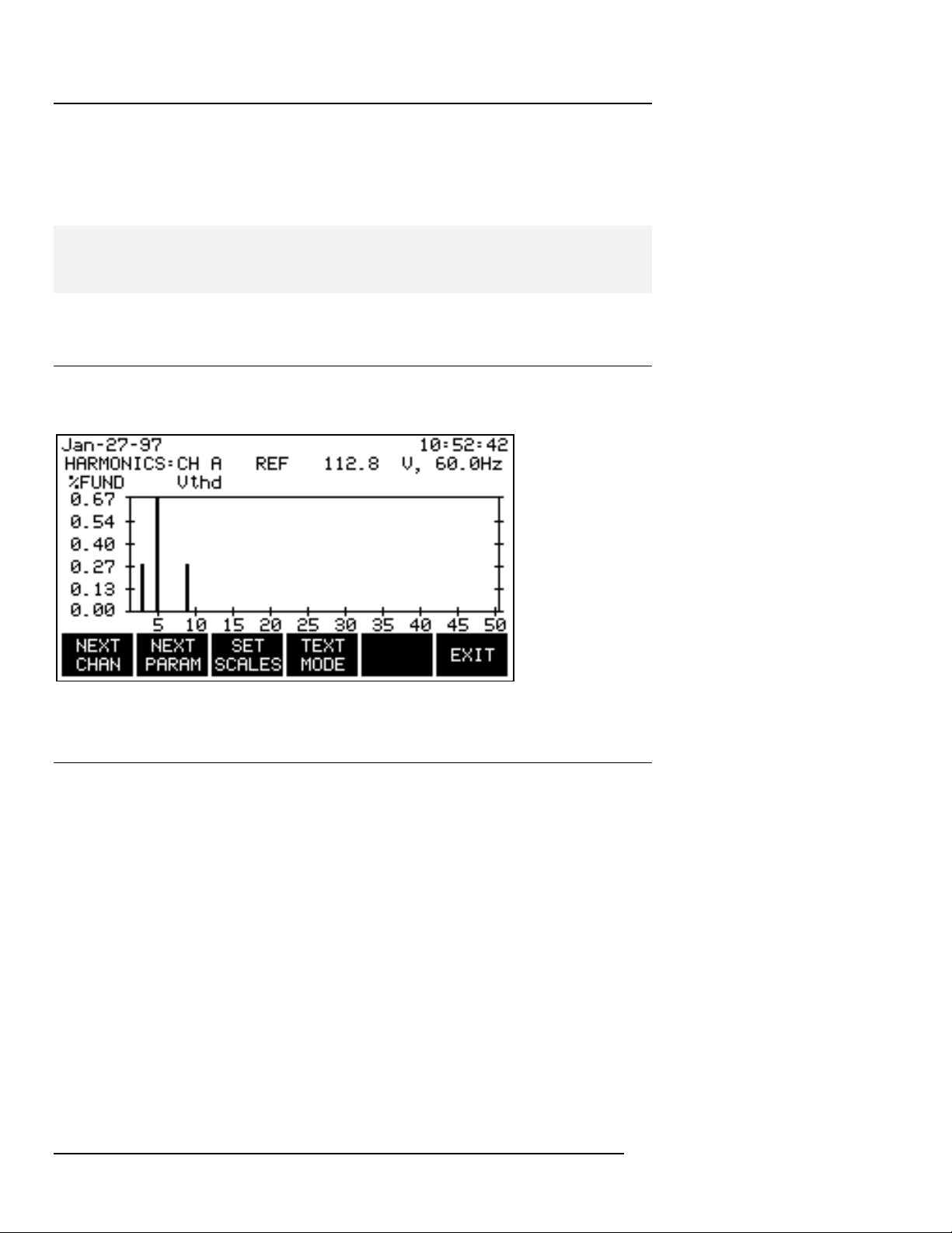
Chapter 7 Reporting Tour
TASK 808
7.3 Viewing Harmonics
NOTE - The harmonics feature is only available on Task 808 model
808/H-M.
Step 1 Press the HARMONICS SOFTKey to view harmonics graphs and
text screens:
Step 2 Explore some options -- press the NEXT CHAN SOFTKey to
advance through the channels. Press the NEXT PARAM SOFTKey to
change parameters (by highlighting and selecting the desired parameter
from a list).
Press the SET SCALES SOFTKey to toggle the vertical scale between %
of fundamental (amount of fundamental frequency, e.g., 50Hz or 60Hz) and
% of RMS.
Press the TEXT MODE SOFTKey to switch from a graphical to a text
format display:
Page 68
Page 87
Chapter 7 Reporting Tour
TASK 808
Jan-17-97
HARMONICS:CH A REF 117.8 V,
% FUND Vthd
H# MAG% PHS H# MAG% PHS H# MAG% PHS
02 0.038 094 09 0.038 074 16 0.019 115
03 4.981 205 10 0.019 218 17 0.132 143
04 0.094 186 11 0.338 020 18 0.019 269
05 2.331 177 12 0.019 332 19 0.094 024
06 0.019 138 13 0.169 339 20 0.019 341
07 0.808 175 14 0.000 206 21 0.282 193
08 0.019 044 15 0.188 279 22 0.019 088
NEXT NEXT NEXT GRAPH
CHAN PARAM SET MODE EXIT
60.0Hz
18:34:45
Mag% is the amplitude of the harmonic. PHS is the phase angle between
the harmonic and fundamental of the channel displayed.
NOTE - The watts parameter version of this screen indicates harmonic
power direction by the sign in front of the MAG% value. A minus sign (-)
indicates that the harmonic power flows from the load to the source. No
sign indicates that the harmonic power flows from the source to the load.
Step 3 There are three sets of harmonics. Press the NEXT SET
SOFTKey to display additional sets of harmonics until the maximum of 50
harmonics is reached. Exit from the “Harmonics” menu and return to the
“Scope Mode” screen by pressing the EXIT SOFTKey.
7.4 Screen Printing
The currently displayed screen may be printed (using the optional printer)
by pressing the period key (.) on the numeric keypad.
This completes the Reports Guided Tour.
Page
69
Page 88

Page 89

Appendix A Product Support
TASK 808
Appendix A Product support
Dranetz-BMI provides users with complete technical support.
A.1 Telephone Support
Technical Support and Customer Service is available toll-free, Monday
through Friday during normal business hours (Eastern Time) by calling:
1-800-372-6832 or 732-287-3680
A.2 Fax Line
Customers may send fax inquiries to the Dranetz-BMI Customer Service
Fax line at any time:
732-248-1834
A.3 World Wide Web
Customers may also check the Dranetz-BMI Web page for additional
product and technical information:
http://www.dranetz-bmi.com
A.4 Technical support email address
Page
71
Page 90

Page 91

Appendix B Maint/Service/Return
TASK 808
Appendix B Maintenance/Servicing/Return
Shipment
B.1 Maintenance/Servicing
No maintenance is required for the PP4300 other than internal battery
replacement and calibration.
B.1.1 Internal Battery Pack Replacement
The internal battery pack used in the PP4300 functions as a power source
and UPS. Replacement procedures follow the specifications and
precautions below. See Appendix F for memory card battery
replacement.
Battery Pack Specifications
Location: Battery compartment on the bottom of the unit.
Number of batteries in pack: 6
Type: Sealed, rechargeable NiCad cells
Voltage: 7.2 V dc
Capacity: 1.6 Ah
Length of operation : More than two hours when fully charged and properly
maintained.
Suggested replacement interval : Two years.
Part Number: BP4300
NOTE - The length of time that the PP4300 can operate on the battery
pack degrades over the life of the batteries and the number of
charge/discharge cycles.
Page
73
Page 92

Appendix B Maint/Service/Return
TASK 808
Memory backup
A storage capacitor on the CPU board is used for backup of the
PP4300's data, configurations, and setup when the battery pack is
removed. The capacitor's charge will maintain memory for two hours,
meaning that if the battery pack is replaced within two hours, no data will
be lost from the internal memory . The capacitor is not operator
replaceable.
Battery Pack Safety Precautions
• WARNING: DO NOT intentionally short circuit the battery pack.
The batteries are capable of providing hazardous output
currents if short circuited. The Power Platform is equipped with
an internal battery charger circuit. Do not attempt to charge the
batteries with an external charger other than the Dranetz-BMI
battery charger, since improper charging could cause battery
explosion.
• ADVERTENCIA: NO ponga intencionalmente la batería en
cortocircuito. Las baterías son capaces de proporcionar
corrientes de salida peligrosas si están en cortocircuito. La
Power Platform está equipada con un circuito interno cargador
de baterías. No intente cargar las baterías con un cargador
externo que no sea el cargador de baterías Dranetz-BMI, puesto
que la carga indebida podría hacer que explote la batería.
• AVERTISSEMENT: NE PAS court-circuiter délibérément le bloc-
batterie. Lors d'un court-circuit, les batteries risquent d'é
mettre des courants effectifs dangereux. “Power Platform”
possède un circuit de chargeur de batterie int égré. Ne pas
tenter de charger les batteries au moyen d'un chargeur externe
autre que le chargeur de batterie Dranetz-BMI, car un
rechargement fautif pourrait entraîner l'explosion de la batterie.
• WARNUNG: Die Batterien dürfen NICHT kurzgeschlossen
werden. Im Falle eines Kurzschlusses können die Batterien
lebensgefährliche Ausgangsströme leiten. Power Platform ist
mit einem internen Batterieladegerät ausgestattet. Die Batterien
sollten nur mit dem Ladegerät von Dranetz-BMI geladen
werden. Die Verwendung eines externen Ladegeräts kann zu
einer Explosion der Batterien führen.
Page 74
Page 93

Appendix B Maint/Service/Return
TASK 808
Battery Safety Precautions
The following safety precautions must be adhered to.
o Keep batteries away from children. Never permit a child to play with a
battery as an ornament or toy.
o Do not disassemble battery or battery pack.
o Do not dispose of battery in fire.
o Dispose of a used battery promptly in accordance with local
Environmental Protection Agency (EPA) regulations.
o Visually inspect the battery pack for corrosion.
Medidas de seguridad de la batería
Deberán observarse las medidas de seguridad siguientes:
o No deberá mantenerse las baterías al alcance de los niños. No
deberá permitirse que un niño juegue con una batería.
o No deberá desensamblarse ninguna batería ni el compartimiento de
la misma.
o No deberá prenderse fuego a una batería.
o Toda batería agotada deberá desecharse de manera rápida según
las normas locales de la Agencia de protección del medio ambiente
(EPA).
o Deberá verificarse que el compartimiento de las baterías no esté
corroído.
Mesures de sécurité relatives aux batteries
Il est très important de suivre les mesures de sécurité suivantes.
o Ne pas laisser les batteries à la portée des enfants. Ne jamais laisser
un enfant jouer avec une batterie.
o Ne pas démonter de batterie ou de bloc-batterie.
o Ne pas jeter de batterie dans le feu.
o Se débarrasser rapidement des batteries usagées en se conformant
aux règlements de l’EPA (Agence américaine pour la protection de
l’environnement).
o Inspecter le bloc-batterie à l’oeil nu pour rechercher les signes de
corrosion.
Batterie-Sicherheitsvorkehrungen
Die folgenden Sicherheitsvorkehrungen müssen beachtet werden.
Page
75
Page 94

Appendix B Maint/Service/Return
TASK 808
o Halten Sie Batterien von Kindern fern. Erlauben Sie einem Kind unter
keinen Umständen, eine Batterie als Verzierung oder Spielzeug zu
benutzen.
o Nehmen Sie Batterien oder Batteriepackungen nicht auseinander.
o Entsorgen Sie Batterien nicht durch Verbrennen.
o Entsorgen Sie verbrauchte Batterien umgehend nach den gesetzlichen
Umweltschutzbestimmungen.
o Prüfen Sie die Batteriepackung optisch auf Korrosion.
The batteries have a safety pressure vent to prevent excessive gas
build-up. Corrosion indicates that venting has occurred. Possible
causes of venting are: a defective charger, excessive temperature,
excessive discharge rate, or a defective cell.
If corrosion is excessive, the battery pack may require replacement.
Contact Dranetz-BMI Customer Service Department.
Battery Pack Replacement
The PP4300 contains an easily replaceable internal battery pack.
n Refer to Appendix D for ordering information.
• WARNING: Replace with Dranetz-BMI NiCad battery pack
BP4300 only.
• ADVERTENCIA: Reemplace con bateria Dranetz-BMI NiCad
BP4300 solamente.
• AVERTISSEMENT: Remplacer par la batterie Dranetz-BMI
NiCad BP4300 exclusivement.
• WARNUNG: Nur mit Dranetz-BMI NiCad BP4300 Batteriesatz
auswechseln.
NOTE - During normal operation, the battery pack will be slightly warm
to the touch.
Page 76
Page 95
Appendix B Maint/Service/Return
TASK 808
Procedure
Follow these steps to replace the battery pack.
Step Action
1 Turn OFF power to the circuit being measured.
2 Press the PP4300 power key to OFF.
3 Disconnect voltage and current probes from the circuit and
the PP4300's rear panel.
4 On the bottom of the PP4300, push the tab to release the
battery cover.
5 Remove the cover.
6 Pull up on removal strap and remove battery pack.
7 Insert the new pack into the compartment making sure to
observe polarity markings.
8 Replace the cover and press down until it latches closed.
9 If discarding the old battery pack, do so in accordance with
Environmental Protection Agency (EPA) regulations.
10 Press the PP4300 power key to on.
B.1.2 Calibration
The recommended calibration interval for the PP4300 is once every 12
months.
n Refer to Return Shipment section below for instructions.
B.3 Return Shipment
Notify Dranetz-BMI Customer Service of your intention to return any
product for any reason, including calibration. Do not return the unit, for any
reason, without prior approval and instructions from Dranetz-BMI.
To return the PP4300 to Dranetz-BMI for calibration, first contact DranetzBMI Customer Service department for a Return Material Authorization
(RMA) number.
Telephone: 1-800-372-6832 or 732-287-3680
Fax: 732-248-1834
Page
77
Page 96

Appendix B Maint/Service/Return
TASK 808
Insert correspondence with instructions and RMA reference number inside
the package.
If the unit is returned to Dranetz-BMI for service or repair, wrap the unit
securely in heavy packing material and place in a well padded box or
crate to prevent shipping damage. If possible, return the unit in its original
packing carton or container.
Dranetz-BMI will not be responsible for damage incurred during transit due
to inadequate packing by customer.
B.3.1 Shipping Address
Ship packages to:
Customer Service Department
Dranetz-BMI
1000 New Durham Road
Edison, NJ 08818
Page 78
Page 97
Appendix C Optional Accessories
TASK 808
Appendix C Optional Accessories
C.1 Introduction
This appendix lists the optional accessories that are available for the
PP4300. Descriptions for some of the accessories follow the list.
C.2 Optional Accessories List
Accessory Part Number
Adapter Cable, 658 Current Probe to PP4300 CA4300
Battery Pack (7.2V at 1.6A) BP4300
Current Probe, 1 to 500 A TR2500
Current Probe, 1 to 30 A TR2021
Current Probe, 1 to 300 A TR2019B
Current Probe, 10 to 1000 A TR2022
Current Probe, 10 to 3000 A TR2023
Current Probe, 0.1 to 10 A TR2510
Current Probe, 10 to 3000 A TR2520
DRAN-VIEW Windows PC Software 4300EA
4300EA driver
External Battery Charger XBC4300
Field Handbook for Electrical Energy
Management
Field Handbook for Power Quality Analysis HB114414
Isolated Communications Module PP4300RS232
Isolated Current Transformer ISO-65X-5
Lockable Portable Case LPC4300
Memory Card, 512k CARD-512
Memory Card, 1M CARD-1M
Memory Card, 2M CARD-2M
Memory Card, 4M CARD-4M
Memory Card Reader, Data Bus Plug-in
Memory Card Reader, Parallel Port
Memory Card Reader, Parallel Port, 230 V
Memory Card Reader, Serial Port
Memory Card Reader, Serial Port, 230 V
Portable Field Printer PFP4300
HB114415
Page
79
Page 98
Appendix C Optional Accessories
TASK 808
Reusable Shipping Container RSC4300
Soft Carrying Case SCC4300
TASKCard 808/M Task-808M
TASKCard 808/H-M Task-808H/M
TASKCard-PQLite TASK-PQLITE
TASKCard-PQLite w/Harmonics TASK-PQLITE/H
TASKCard-PQLite w/Harmonics & Memory
Card Functions
TASKCard-PQLite w/Harmonics & Transient
Capture
TASKCard-PQLite w/Harmonics, Transient
Capture, & Memory Card Functions
TASKCard-PQLite w/Harmonics, Transient
Capture, Memory Card & Energy Functions
Voltage Cable Accessory Pack VCP4300
TASK-PQLITE/H/M
TASK-PQLITE/H/T
TASK-PQLITE/H/T/M
TASK-
PQLITE/H/T/M/E
C.2.1 Optional Accessories Descriptions
Adapter cable, 658 current probes to PP4300
This cable allows connection of current probes made for the Dranetz-BMI
Model 658 to the PP4300 current input jacks.
Battery Pack
The internal battery pack, containing six sealed, rechargeable NiCad
batteries, is used as the PP4300’s primary power source and UPS.
These batteries have a length of operation of more than two hours when
fully charged and properly maintained.
Current probes
There are seven Dranetz-BMI current probes which can be used with the
PP4300: models TR2500, TR2510, TR2520, TR2021, TR2019B,
TR2022, TR2023.
TR2500, TR2510, TR2520: These models will measure rms currents from
1 to 500 A, 0.1 to 10 A, 10 to 3000 A, respectively, and plug directly into
any of the current inputs on the rear panel.
TR2021, TR2019B, TR2022, TR2023: These four probes were initially
made for the Dranetz-BMI model 658 but can be used with the PP4300 by
using an adapter cable (part number 116002-G1). They can measure rms
currents in the ranges of 0 to 30 A, 1 to 300 A, 10 to 1000 A, and 10 to
3000 A, respectively.
Page 80
Page 99

Appendix C Optional Accessories
TASK 808
Page
81
Page 100

Appendix C Optional Accessories
TASK 808
Memory cards
Memory cards are available in 512K, 1Mb, 2Mb and 4Mb capacities, and
are recommended for most applications.
External Battery Charger
This device charges a battery pack while the PP4300 is in use.
Field Handbook for Electrical Energy Management
This reference handbook provides a comprehensive guide for information
related to conducting a thorough energy audit, power distribution analysis,
and methods of remedying inefficiencies of energy management.
Field Handbook for Power Quality Analysis
This handbook is divided into six sections containing step-by-step
instructions for discovering and solving complex power quality problems.
Example waveforms and case studies are included.
Isolated Communications Module
The communications module is an optically isolated device using infrared
light to transfer text and graphics to a PC or printer. The communications
module is designed to connect the Dranetz-BMI PP4300 optical serial
port to a standard RS232 serial port. This interface can be connected to
an Epson graphics-compatible printer for printing screens, or to a PC
running DRAN-LINK to download data. This data can then be viewed
using the DRAN-VIEW application.
Isolated Current Transformer
This device allows the connection of other industry-standard 5A output
current transformers to Dranetz-BMI equipment.
Lockable Portable Case
The Lockable Portable Case is an optional accessory for the Power
Platform 4300 (PP4300). It consists of a rugged, high impact plastic case,
a voltage measurement cable assembly and a domestic 115 VAC cable
assembly. The cables, case and all connections are waterproof and
designed to meet NEMA 4X requirements. The LPC4300 allows the
PP4300 to be operated and left unattended in harsh industrial
environments.
Memory card readers
Three types of memory card readers are available as options. Each
reader provides a different means of communications with an IBM
compatible computer. The three types are: RS232 serial port, parallel
port, and data bus plug-in.
Page 82
 Loading...