

Dranetz PowerVisa User Manual

PowerVisaTM
USER’S GUIDE
DRANETZ - BMI
1000 New Durham Road
Edison, New Jersey 08818-4019

WARNING
Death, serious injury, or fire hazard could result from improper connection of this instrument. Read and
understand this manual before connecting this instrument. Follow all installation and operating
instructions while using this instrument.
Connection of this instrument must be performed in compliance with the National Electrical Code (ANSI/
NFPA 70-2005) of USA and any additional safety requirements applicable to your installation.
Installation, operation, and maintenance of this instrument must be performed by qualified personnel
only. The National Electrical Code defines a qualified person as “one who has the skills and knowledge
related to the construction and operation of the electrical equipment and installations, and who has
received safety training on the hazards involved.”
Qualified personnel who work on or near exposed energized electrical conductors must follow applicable
safety related work practices and procedures including appropriate personal protective equipment in
compliance with the Standard for Electrical Safety Requirements for Employee Workplaces (ANSI/NFPA
70E-2004) of USA and any additional workplace safety requirements applicable to your installation.
Published by Dranetz-BMI
1000 New Durham Road
Edison, NJ 08818-4019 USA
Telephone: 1-800-372-6832 or 732-287-3680
Fax: 732-248-1834
Web site: www.dranetz-bmi.com
Copyright © 2005 Dranetz-BMI
All rights reserved.
No part of this book may be reproduced, stored in a
retrieval system, or transcribed in any form or by any
means—electronic, mechanical, photocopying, recording,
or otherwise—without prior written permission from the
publisher, Dranetz-BMI, Edison, NJ 08818-4019.
Printed in the United States of America.
ii

ADVERTENCIA
Una conexión incorrecta de este instrumento puede producir la muerte, lesiones graves y riesgo de
incendio. Lea y entienda este manual antes de conectar. Observe todas las instrucciones de instalación y
operación durante el uso de este instrumento.
La conexión de este instrumento debe ser hecha de acuerdo con las normas del Código Eléctrico Nacional
(ANSI/NFPA 70-2005) de EE. UU., además de cualquier otra norma de seguridad correspondiente a su
establecimiento.
La instalación, operación y mantenimiento de este instrumento debe ser realizada por personal calificado
solamente. El Código Eléctrico Nacional define a una persona calificada como "una que esté familiarizada
con la construcción y operación del equipo y con los riesgos involucrados."
AVERTISSEMENT
Si l'instrument est mal connecté, la mort, des blessures graves, ou un danger d'incendie peuvent s'en
suivre. Lisez attentivement ce manuel avant de connecter l'instrument. Lorsque vous utilisez l'instrument,
suivez toutes les instructions d'installation et de service.
Cet instrument doit être connecté conformément au National Electrical Code (ANSI/NFPA 70-2005) des
Etats-Unis et à toutes les exigences de sécurité applicables à votre installation.
Cet instrument doit être installé, utilisé et entretenu uniquement par un personnel qualifié. Selon le
National Electrical Code, une personne est qualifiée si "elle connaît bien la construction et l'utilisation de
l'équipement, ainsi que les dangers que cela implique".
WARNUNG
Der falsche Anschluß dieses Gerätes kann Tod, schwere Verletzungen oder Feuer verursachen. Bevor Sie
dieses Instrument anschließen, müssen Sie die Anleitung lesen und verstanden haben. Bei der
Verwendung dieses Instruments müssen alle Installation- und Betriebsanweisungen beachtet werden.
Der Anschluß dieses Instruments muß in Übereinstimmung mit den nationalen Bestimmungen für
Elektrizität (ANSI/NFPA 70-2005) der Vereinigten Staaten, sowie allen weiteren, in Ihrem Fall
anwendbaren Sicherheitsbestimmungen, vorgenommen werden.
Installation, Betrieb und Wartung dieses Instruments dürfen nur von Fachpersonal durchgeführt werden.
In dem nationalen Bestimmungen für Elektrizität wird ein Fachmann als eine Person bezeichnet, welche
"mit der Bauweise und dem Betrieb des Gerätes sowie den dazugehörigen Gefahren vertraut ist."
iii

Safety Summary
Definitions
Symbols
Definiciones
WARNING statements inform the user that certain conditions or practices could result
in loss of life or physical harm.
CAUTION statements identify conditions or practices that could harm the PowerVisa,
its data, other equipment, or property.
NOTE statements call attention to specific information.
The following International Electrotechnical Commission (IEC) symbols are marked
on the top and rear panel in the immediate vicinity of the referenced terminal or device:
!
Las ADVERTENCIAS informan al usuario de ciertas condiciones o prácticas que
podrían producir lesiones mortales o daño físico.
Las PRECAUCIONES identifican condiciones o prácticas que podrían dañar la
PowerVisa, sus datos, otros equipos o propiedad.
Caution, refer to accompanying documents (this manual).
Direct current (DC) operation of the terminal or device.
Power Switch
Símbolos
Las NOTAS llaman la atención hacia la información específica.
Los siguientes símbolos de la Comisión Internacional Electrotécnica (IEC) aparecen
marcados en el panel superior y el posterior inmediatos al terminal o dispositivo en
referencia:
!
Precaución, consulte los documentos adjuntos (este manual).
Operación de corriente continua (CC) del terminal o dispositivo.
Interruptor de encendido
Continued on next page
iv

Safety Summary, Continued
Définitions
Symboles
Definitionen
Les messages d’AVERTISSEMENT préviennent l’utilisateur que certaines conditions
ou pratiques pourraient entraîner la mort ou des lésions corporelles.
Les messages de MISE EN GARDE signalent des conditions ou pratiques susceptibles
d’endommager “PowerVisa”, ses données, d’autres équipements ou biens matériels.
Les messages NOTA attirent l’attention sur certains renseignements spécifiques.
Les symboles suivants de la Commission électrotechnique internationale (CEI) figurent
sur le panneau arrière supérieur situé à proximité du terminal ou de l’unité cité:
!
WARNUNGEN informieren den Benutzer darüber, daß bestimmte Bedingungen oder
Vorgehensweisen körperliche oder tödliche Verletzungen zur Folge haben können.
VORSICHTSHINWEISE kennzeichnen Bedingungen oder Vorgehensweisen, die zu
einer Beschädigung von PowerVisa, seiner Daten oder anderer Geräte bzw. von
Eigentum führen können.
Mise en garde, consultez les documents d’accompagnement (ce manual).
Fonctionnement du terminal ou de l’unité en courant continu (CC).
Interrupteur de tension
Symbole
HINWEISE machen auf bestimmte Informationen aufmerksam.
Die folgenden Symbole der Internationalen Elektrotechnischen Kommission
(International Electrotechnical Commission; IEC) befinden sich auf der Abdeck- und
Seitenplatte unmittelbar am betreffenden Terminal oder Gerät.
!
Vorsichtshinweis, siehe Begleitdokumente (dieses Handbuch).
Gleichstrombetrieb im Terminal oder Gerät.
Netzschalter
Continued on next page
v

Safety Summary, Continued
Safety
precautions
The following safety precautions must be followed whenever any type of voltage or
current connection is being made to the PowerVisa.
• Wear proper Personal Protective Equipment, including safety glasses and insulated
gloves when making connections to power circuits.
• Hands, shoes and floor must be dry when making any connection to a power line.
• Before each use, inspect all cables for breaks or cracks in the insulation. Replace
immediately if defective.
• Set the PowerVisa power switch to Off.
• Before connecting to electric circuits to be monitored, open their related circuit
breakers or disconnects. DO NOT install any connection of the PowerVisa to live
power lines.
• Connections must be made to the PowerVisa first, then connect to the circuit to be
monitored.
These safety precautions are repeated where appropriate throughout this manual.
vi

Statements and Notices
Statement of
warranty
Statement of
reliability
Notice regarding
FCC compliance
All products of Dranetz-BMI are warranted to the original purchaser against defective
material and workmanship for a period of one year from the date of delivery. DranetzBMI will repair or replace, at its option, all defective equipment that is returned, freight
prepaid, during the warranty period. There will be no charge for repair provided there is
no evidence that the equipment has been mishandled or abused. This warranty shall not
apply to any defects resulting from improper or inadequate maintenance, buyersupplied hardware/software interfacing, unauthorized modification or misuse of the
equipment, operation outside of environmental specifications, or improper site
preparation or maintenance.
The information in this manual has been reviewed and is believed to be entirely
reliable, however, no responsibility is assumed for any inaccuracies. All material is for
informational purposes only and is subject to change without prior notice.
This device has been tested and found to comply with the limits for a Class A digital
device, pursuant to Part 15 of the FCC Rules. These limits are designed to provide
reasonable protection against harmful interference when the equipment is operated in a
commercial environment. This equipment generates, uses, and can radiate radio
frequency energy and, if not installed and used in accordance with the instruction
manual, may cause harmful interference to radio communications. Operation of this
equipment in a residential area is likely to cause harmful interference in which case the
user will be required to correct the interference at his/her own expense.
Notice regarding
proprietary
rights
This publication contains information proprietary to Dranetz-BMI. By accepting and
using this manual, you agree that the information contained herein will be used solely
for the purpose of operating equipment of Dranetz-BMI.
Continued on next page
vii

Statements and Notices, Continued
Copyright
Trademarks
This publication is protected under the Copyright laws of the United States, Title 17 et
seq. No part of this publication may be reproduced, transmitted, transcribed, stored in a
retrieval system, or translated into any language or computer language, in any form, by
any means, electronic, mechanical, magnetic, optical, chemical, manual, or otherwise,
without the prior written consent of Dranetz-BMI, 1000 New Durham Road, Edison,
New Jersey 08818.
Copyright © 2005 Dranetz-BMI
All Rights Reserved. Printed in the United States of America.
PowerVisa, Scope Mode, NodeLink and DranView are registered trademarks of
Dranetz-BMI.
viii

Table of Contents
Safety Summary .................................................................................................................... iv
Statements and Notices.......................................................................................................... vii
CHAPTER 1 - Getting Started
Overview ............................................................................................................................... 1-1
Unpacking the PowerVisa ..................................................................................................... 1-3
Standard Accessories............................................................................................................. 1-4
PowerVisa Controls, Indicators, and Connectors.................................................................. 1-5
Top and Side Views........................................................................................................ 1-6
Front View ...................................................................................................................... 1-7
Bottom View................................................................................................................... 1-8
Rear View ....................................................................................................................... 1-9
Upgrading Firmware from a Data Card................................................................................. 1-10
PowerVisa Features............................................................................................................... 1-12
Basic Operation ..................................................................................................................... 1-14
Power-on Sequence......................................................................................................... 1-15
Home Screen Icons ......................................................................................................... 1-16
CHAPTER 2 - Voltage Measurement Cable and Current Probe Connections
Overview ............................................................................................................................... 2-1
Connecting Voltage Measurement Cables ............................................................................ 2-4
Connecting Current Probes.................................................................................................... 2-9
CHAPTER 3 - View Real Time Data
Overview ............................................................................................................................... 3-1
Section A -Scope Mode ............................................................................................................... 3-2
Overview ............................................................................................................................... 3-2
Turning Channels On/Off...................................................................................................... 3-3
Checking Input Range........................................................................................................... 3-4
Section B -Meter Mode................................................................................................................ 3-5
Overview ............................................................................................................................... 3-5
Standard Meter Tab ............................................................................................................... 3-6
Distortion Meter Tab............................................................................................................. 3-8
Section C -Harmonics.................................................................................................................. 3-10
Overview ............................................................................................................................... 3-10
Harmonic Graph.................................................................................................................... 3-11
Harmonic Detail .................................................................................................................... 3-12
Harmonic Options.................................................................................................................. 3-13
Harmonic List........................................................................................................................ 3-15
Section D -Voltage and Current Phasor....................................................................................... 3-16
Overview ............................................................................................................................... 3-16
Phasor Screen ........................................................................................................................ 3-17
Phasor Rotation...................................................................................................................... 3-18
Phasor Parameter/Channel Selection..................................................................................... 3-20
ix

Table of Contents, Continued
CHAPTER 4 - Instrument Settings
Overview ............................................................................................................................... 4-1
Access Instrument Settings Menu ......................................................................................... 4-2
Time and Date Settings.......................................................................................................... 4-3
Select Language..................................................................................................................... 4-5
Set Display Preferences......................................................................................................... 4-6
Touch Screen Calibration...................................................................................................... 4-7
Turn Threshold Beeper On/Off ............................................................................................. 4-9
Communications.................................................................................................................... 4-10
Data Card............................................................................................................................... 4-12
Reset to Factory Configurations............................................................................................ 4-14
CHAPTER 5 - Start Menu
Overview ............................................................................................................................... 5-1
Section A -Automatic Setup......................................................................................................... 5-3
Section B -Wizard Setup.............................................................................................................. 5-5
Overview ............................................................................................................................... 5-5
Current Probe Selection......................................................................................................... 5-7
Scale Factor Setup................................................................................................................. 5-9
Circuit Type Selection........................................................................................................... 5-11
Nominal Values..................................................................................................................... 5-13
Mode of Operation................................................................................................................. 5-16
Monitoring Mode................................................................................................................... 5-17
Advanced Options ................................................................................................................. 5-18
Site Name/Memory Card....................................................................................................... 5-19
Section C -Monitor Same Circuit................................................................................................. 5-23
Overview ............................................................................................................................... 5-23
Turning Monitoring On/Off................................................................................................... 5-24
Monitoring at a Specified Time and Date ............................................................................. 5-27
Modify Trigger Parameters and Intervals.............................................................................. 5-32
Section D -Load Setup Template from Card................................................................................ 5-33
Section E -Load Data from Card.................................................................................................. 5-34
Overview ............................................................................................................................... 5-34
Loading Data from Card........................................................................................................ 5-34
Card Error Messages ............................................................................................................. 5-35
CHAPTER 6 - Advanced Setup Options
Overview ............................................................................................................................... 6-1
Advanced Options Menu....................................................................................................... 6-2
Transient Limit...................................................................................................................... 6-3
x

Table of Contents, Continued
RMS Variation Limit............................................................................................................. 6-8
Waveform Capture ................................................................................................................ 6-13
Characterizer Options............................................................................................................ 6-14
Journal Limit.......................................................................................................................... 6-15
Journal Interval for Timed Readings..................................................................................... 6-18
EN50160 Power Quality (for strict EN50160 monitoring only)........................................... 6-20
CHAPTER 7 - View Event Data
Overview ............................................................................................................................... 7-1
Section A -Events......................................................................................................................... 7-4
Overview ............................................................................................................................... 7-4
Event Data Display................................................................................................................ 7-5
Event Activity Graph............................................................................................................. 7-6
Event List............................................................................................................................... 7-7
Event Detail........................................................................................................................... 7-9
Event Options........................................................................................................................ 7-12
Section B -Trend.......................................................................................................................... 7-15
Overview ............................................................................................................................... 7-15
Trend Display ........................................................................................................................ 7-16
Trend Setup............................................................................................................................ 7-17
CHAPTER 8 - Reports
Overview ............................................................................................................................... 8-1
Section A -EN50160.................................................................................................................... 8-2
Overview ............................................................................................................................... 8-2
EN50160 Measurement Parameters ...................................................................................... 8-3
EN50160 Compliance Limits................................................................................................ 8-5
Compliance Statistical Bar Chart .......................................................................................... 8-8
Compliance History............................................................................................................... 8-11
Event Satistics........................................................................................................................ 8-13
Min/Max Table for Power Frequency and RMS Voltage ..................................................... 8-15
Section B -Status Report in Annunciator Panel........................................................................... 8-16
Overview ............................................................................................................................... 8-16
Panel Setup Options............................................................................................................... 8-17
Panel Operation ..................................................................................................................... 8-19
CHAPTER 9 - Downloading Events
Overview ............................................................................................................................... 9-1
External Communication Interface........................................................................................ 9-2
Downloading Events via NodeLink ...................................................................................... 9-10
Viewing Events via DranView.............................................................................................. 9-11
DranView with HASP........................................................................................................... 9-12
xi

Table of Contents, Continued
APPENDIX A - Optional Accessories
Overview ............................................................................................................................... A-1
Hardware Accessories List & Descriptions........................................................................... A-2
Software Accessories List ..................................................................................................... A-8
APPENDIX B - Technical Specifications
Overview ............................................................................................................................... B-1
General................................................................................................................................... B-2
Interfaces ............................................................................................................................... B-3
Measured Parameters............................................................................................................. B-4
Computed Parameters............................................................................................................ B-5
Parameter Settings in Each Monitoring Mode ...................................................................... B-9
TR2500 Current Probe........................................................................................................... B-11
TR2510 Current Probe........................................................................................................... B-12
APPENDIX C - Battery Specifications and Replacement Procedure
Overview ............................................................................................................................... C-1
Battery Specifications............................................................................................................ C-2
Battery Pack Safety Precautions............................................................................................ C-3
Battery Pack Replacement..................................................................................................... C-4
APPENDIX D - User Replaceable Parts List
APPENDIX E - Common Circuit Connections
Overview ............................................................................................................................... E-1
Verifying Voltage and Current Connections......................................................................... E-5
Single Phase........................................................................................................................... E-7
Split Phase ............................................................................................................................. E-8
3 Phase, Four Wire Wye........................................................................................................ E-9
3 Phase (Floating or Grounded) Delta................................................................................... E-10
3 Phase 2-Watt Delta............................................................................................................. E-11
Generic Circuit ...................................................................................................................... E-12
2 1/2 Element Without Voltage Channel B........................................................................... E-13
2 1/2 Element Without Voltage Channel C........................................................................... E-14
Connecting to a Potential Transformer (PT) ......................................................................... E-15
Connecting to a Current Transformer (CT)........................................................................... E-17
Connecting to an Isolated Current Transformer (ISO).......................................................... E-18
APPENDIX F - Event Classification
APPENDIX G - PowerVisa Menu Structure
xii
Dranetz-BMI PowerVisa
TM
xiii


Overview
CHAPTER 1
Getting Started
PowerVisa
description
PowerVisa
firmware
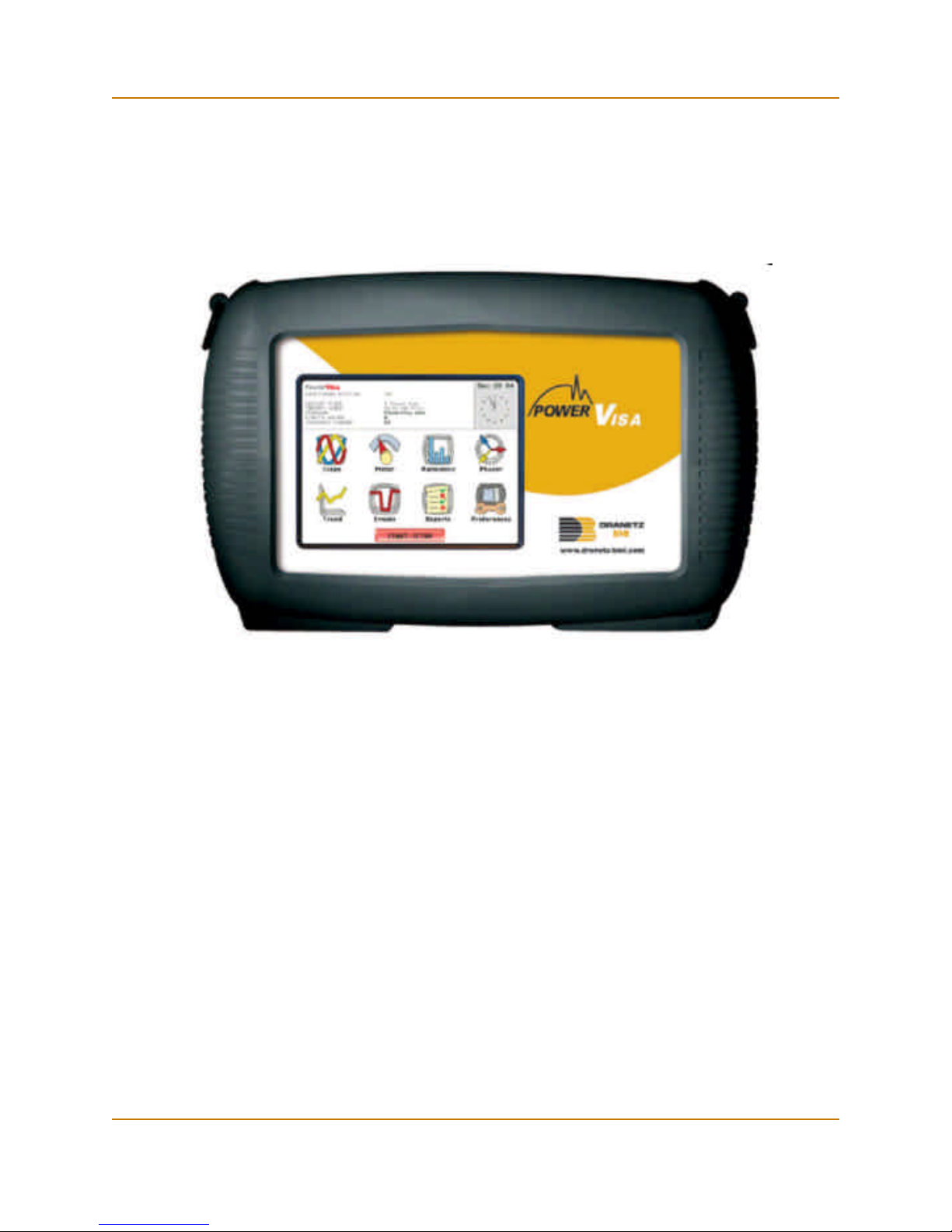
The Dranetz-BMI PowerVisaTM is a portable, hand-held, eight-channel power quality
meter/monitor. This cutting-edge power quality instrument is designed with a color
liquid crystal display (LCD) 1/4 VGA, using touch screen technology. It can monitor,
record and display data on four voltage channels and four current channels
simultaneously.
The PowerVisa is designed to meet both the IEEE 1159 and IEC 61000-4-30 Class A
standards for accuracy and measurement requirements. It can also monitor EN50160
compliance based on the EN (European) Standards. The statistical package called
Quality of Supply (QOS) is built into the PowerVisa, with monitoring and setup
protocols set to determine voltage measurement compliance required for EN50160
monitoring. European standard EN50160 requires that measurement parameters must
be within a specified percentage for 95% of the time.
The firmware for the PowerVisa is contained on internal FLASH memory. It has an
operating system capable of performing multiple applications. When an updated
version of the firmware is released, the user can upgrade the internal program by
putting the latest PowerVisa firmware program card in the appropriate slot of the
mainframe. See page 1-10 for instructions on how to upgrade the PowerVisa
firmware from a data card.
The PowerVisa firmware can monitor power quality phenomena for troubleshooting
and/or compliance purposes. It can carry out long-term statistical studies to establish
performance baselines, and perform field-based equipment testing and evaluation for
commissioning and maintenance. The firmware integrates an intuitive instrument setup
procedure to ensure the capture of all relevant data for additional post process analysis,
report writing, and data archiving using other compatible Dranetz-BMI software
applications such as NodeLink® and DranView®.
This manual
This manual contains instructions for operating the Dranetz-BMI PowerVisa.
1-1

Overview, continued
In this chapter
The following topics are covered in this chapter.
Topic See Page
Unpacking the PowerVisa 1-3
Standard Accessories 1-4
PowerVisa Controls, Indicators and Connectors 1-5
Upgrading Firmware from a Data Card 1-10
PowerVisa Features 1-12
Basic Operation 1-14
1-2

Unpacking the PowerVisa
CH 1/ Getting Started
Introduction
Unpacking
Shipping
damage
inspection
For maximum protection against possible shipping damage, the PowerVisa has been
sealed in a two-piece, plastic suspension pack, enclosed within a durable shipping
carton. After opening the carton, inspect the contents for possible shipping damage and
check the carton inventory.
Unpack the PowerVisa from the carton as follows:
Step Action
1 Remove any remaining literature inside the top of the carton.
2 Carefully remove the PowerVisa from its shipping carton.
3 Remove all accessories inside the carton. Check that all of the standard
accessories (see page 1-4) are included.
Visually inspect the PowerVisa for possible shipping damage. If any damage exists,
first notify and file an insurance claim with your carrier or underwriter or both. Then
notify Dranetz-BMI Customer Service Department of your intentions to return the unit.
DO NOT return the PowerVisa without prior instructions from Dranetz-BMI Customer
Service Department. Dranetz-BMI Customer Service Department can be reached at
(732) 287-3680 or 1-800-372-6832.
Repacking for
return shipment
Return notice
If the unit must be returned to Dranetz-BMI for service or repair, wrap the unit securely
in heavy packaging material and place in a well padded box or crate to prevent damage.
Do not return the PowerVisa in an unpacked box. Dranetz-BMI will not be responsible
for damage incurred during transit due to inadequate packing on your part.
Notify Dranetz-BMI Customer Service of your intention of returning the unit. Do not
return the unit without prior instructions from Dranetz-BMI. Dranetz-BMI Customer
Service Department can be reached at (732) 287-3680 or 1-800-372-6832.
1-3

Standard Accessories
Standard Accessories
Standard
accessories
Optional
accessories
Batteries
The following table lists the PowerVisa's standard accessories.
Description Part Number
Cable Set 116042-G3
Easel 116038-G1
AC Adapter 117029-G1
*US Power Cord USSTDCORD (900744)
*European Power Cord EUROSTDCORD (115369-G2)
*United Kingdom Power Cord UKSTDCORD (115368-G2)
*Australian Power Cord AUSTDCORD (901347)
Notice: Charge Battery 899117
*User specified, one standard only.
Refer to Appendix A for the list of hardware and software optional accessories
available for use with PowerVisa.
Refer to Appendix C for the description and replacement of the batteries contained in
PowerVisa.
Replaceable
parts
Calibration
Refer to Appendix D for the user replaceable parts.
The recommended calibration interval for this unit is once every 12 months.
We recommend that you return the unit to the factory for calibration. If you decide to
do so, first contact the Dranetz-BMI Customer Service Department to obtain an
Authorization Number.
Telephone: (732) 287-3680 or 1-800-372-6832
FAX: (732) 248-9240
Fill out the Repair/Service Order form enclosed in the shipping carton and ship it along
with the unit to the Dranetz-BMI Repair Department. (If this form is missing, ask the
Dranetz-BMI Customer Service Department for a replacement.)
1-4
PowerVisa Controls, Indicators, and Connectors
CH 1/ Getting Started
Dimensions
PowerVisa is a self-contained, portable instrument weighing less than 4 pounds and
measuring 8" (20.3 cm) deep by 12" (30.5 cm) wide by 2.5" (6.4 cm) high. This section
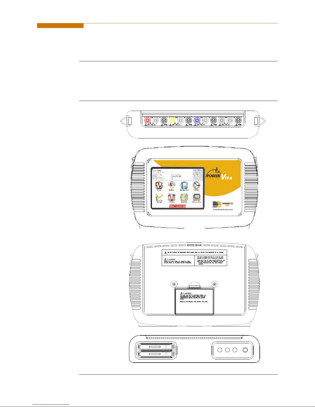
identifies and describes the controls, indicators, and connectors on all panels of the
PowerVisa shown with rubber boot installed.
Top View
Front View
Rear View
Bottom View
SLOT 1
SLOT 2
1-5
PowerVisa Controls, Indicators, and Connectors, continued
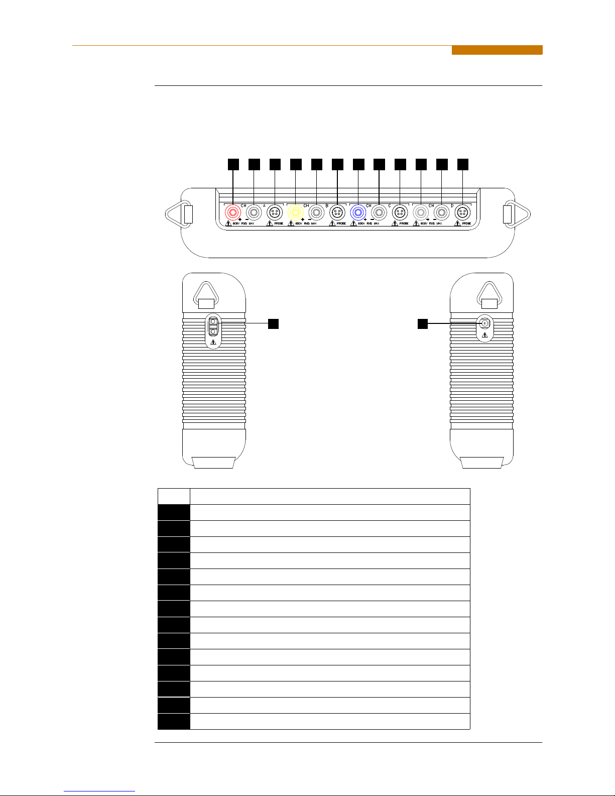
Top and Side
views
The top (circuit connection) view features the input voltage and current connectors.
The left side contains the optical interface port. The right side contains the AC adapter
input connector. Both sides have rings for attaching the supplied carrying strap. See
below for descriptions of the top and side connectors.
1 2 3 5 6 7 8 9 10 11 124
13 14
Parts table
1-6
Part Function
1 CH A, + Differential Voltage Input Connector; color red.
2 CH A, - Differential Voltage Input Connector; color white.
3 CH A, PROBE, Current Input Connector.
4 CH B, + Differential Voltage Input Connector; color yellow.
5 CH B, - Differential Voltage Input Connector; color white.
6 CH B, PROBE, Current Input Connector.
7 CH C, + Differential Voltage Input Connector; color blue.
8 CH C, - Differential Voltage Input Connector; color white.
9 CH C, PROBE, Current Input Connector.
10 CH D, + Differential Voltage Input Connector; color grey.
11 CH D, - Differential Voltage Input Connector; color white.
12 CH D, PROBE, Current Input Connector.
13 Optical Serial Data Port
14 AC Adapter/Battery Charger Input Connector.
CH 1/ Getting Started
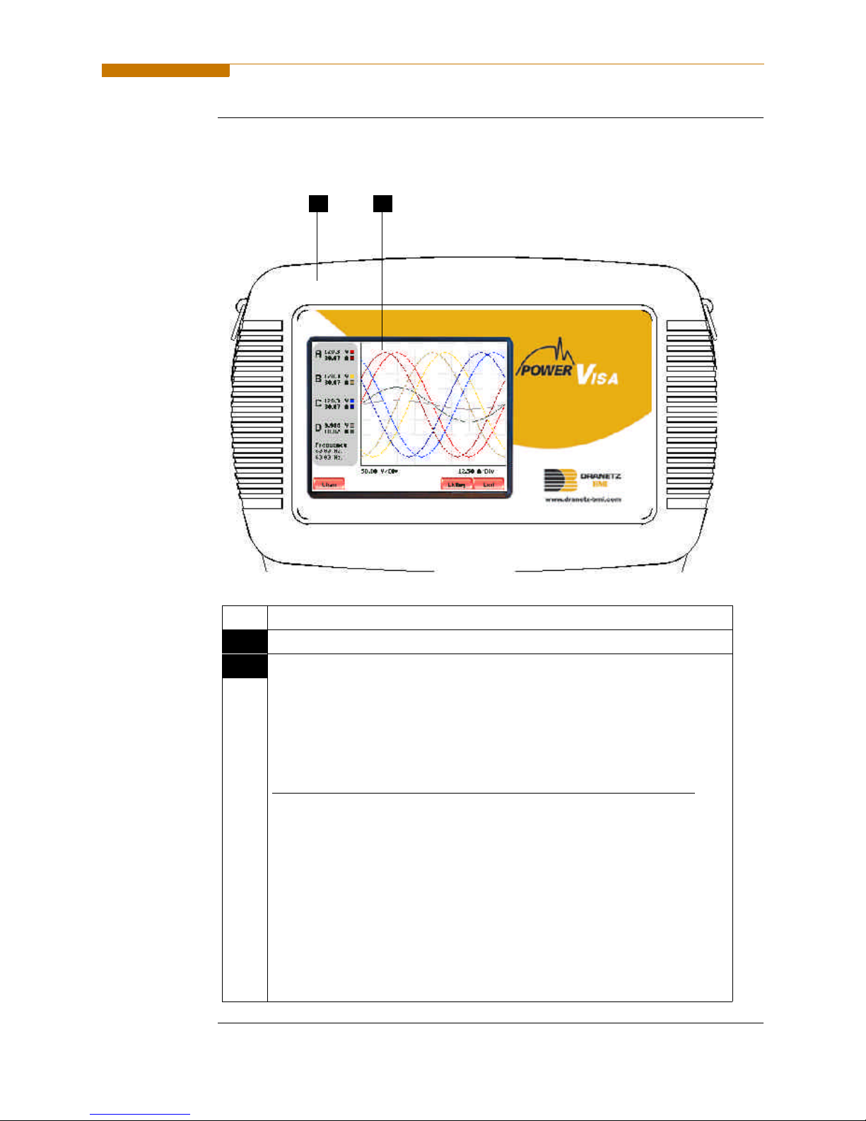
Front view
The front view primarily shows the color touch screen LCD. See below for descriptions
of the PowerVisa front panel.
21
Parts table
Part Function
1 Mainframe Protective Rubber Boot Enclosure
2 Liquid Crystal Display (LCD). Provides 3.75 x 4.75 inches display
consisting of 1/4 VGA size screen of text and graphic information. The
color LCD is equipped with touch screen technology, operable using the
finger and/or PDA stylus. Touch screen display permits menu selection,
alphanumeric data entry, and has a compact fluorescent (CCFL)
backlighting that is always on for low light level viewing.
The following are some basic care instructions for the LCD monitor:
• Use and store the unit within the specified temperature and humidity
range. The LCD screen may be adversely affected by exposure to high
temperature or humidity. Condensation or moisture produced by
sudden temperature changes may also damage the LCD screen. Clean
any moisture from surface immediately.
• Be careful when cleaning or removing stains on the LCD surface.
Gently wipe the surface with a soft cloth or cotton pad. Isopropyl
alcohol may be used, but make sure that all solvent residue is removed.
• Do not apply excessive force to the LCD surface. The LCD screen
contains sensitive electronic components that may be damaged due to
strong impact.
1-7
PowerVisa Controls, Indicators, and Connectors, continued
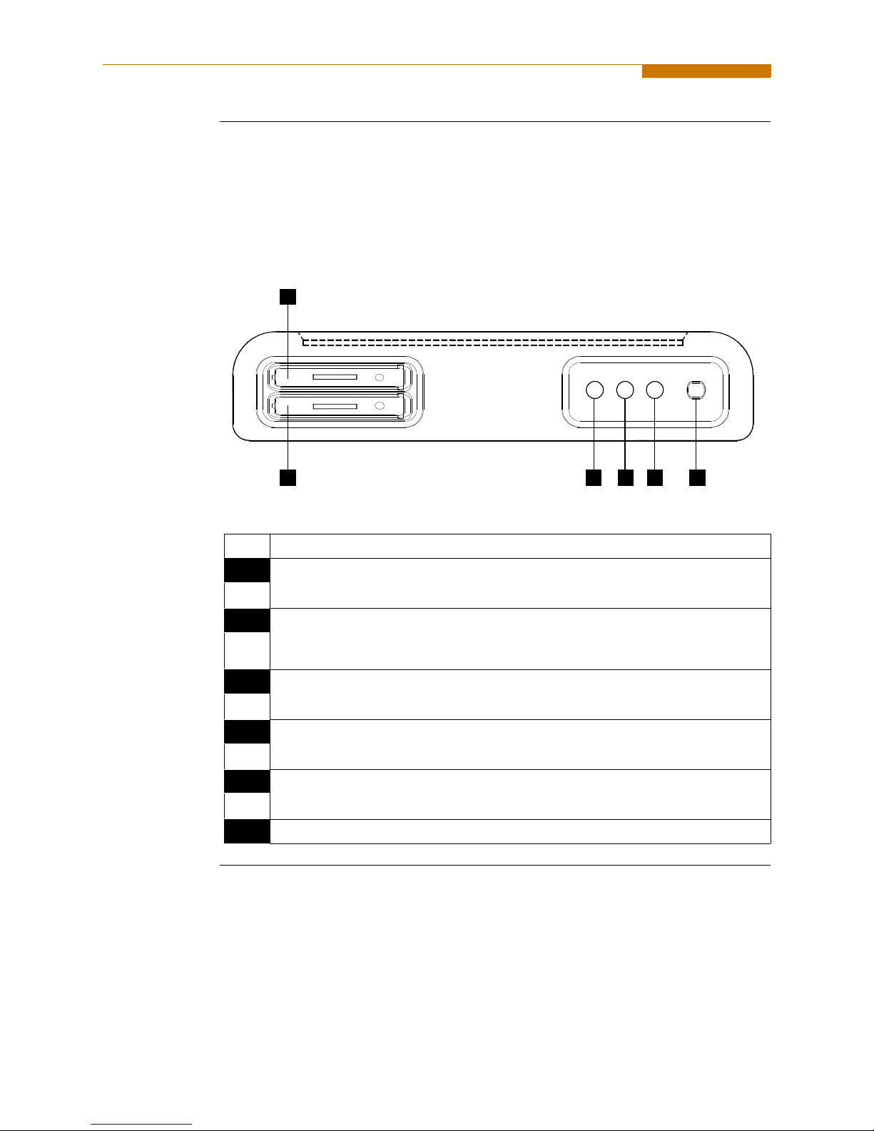
Bottom view
Parts table
The bottom view features two slots. Either slot can be used to hold the data card.
NOTE: Use only one card slot (one data card) at a time. The additional slot will be used
for future communications options.
The bottom also features LED indicators and the On/Off power button. See below for
descriptions of the slots, indicators, and button.
1
SLOT 1
SLOT 2
2 3 5 64
Part Function
1 Slot 1. Holds and connects data card to internal circuitry. Data card works in
either Slot 1 or Slot 2. Eject data card by pushing data card release.
2 Slot 2. Holds and connects data card to internal circuitry. Data card works in
either Slot 1 or Slot 2. Eject data card by pushing data card release.
NOTE: This additional slot will be used for future options.
3 Battery Charge Indicator. LED will light steadily while battery is fast
charging and blink when fully charged.
4 Status Indicator. LED will light steadily when abnormal condition is detected.
The unit is operating normally when light is off.
5 Power Indicator. LED will blink in a heartbeat fashion (once per second) when
the unit is operating normally.
6 On/Off Power Button. Push for on, push for off.
1-8
CH 1/ Getting Started
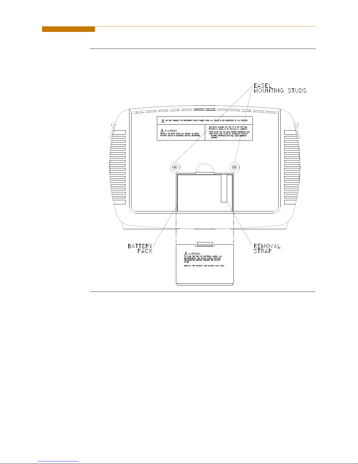
Rear view
The rear view shows the battery compartment and the easel studs to mount the unit to
desired angular position for use on a flat surface or to hang from a panel.
1-9

Upgrading Firmware from a Data Card
Upgrading Firmware from a Data Card
PowerVisa
firmware web
upgrade
Copy firmware
program in data
card
Users can upgrade the PowerVisa internal program by downloading the latest
firmware update release from the web and installing it into the PowerVisa
internal memory. Refer to the instructions below on how to upgrade the
PowerVisa firmware.
Firmware upgrades for the PowerVisa can be downloaded from the DranetzBMI website. Log on to www.dranetz-bmi.com for the latest information on
PowerVisa firmware update releases.
The procedure below specifies how to download the latest PowerVisa firmware from
the web and copy it into a data card.
Step Action
1 Locate the latest version of the firmware upgrade (in data file format
“hostcode.bin”) from the Dranetz-BMI website www.dranetz-bmi.com.
Dranetz-BMI regularly posts the latest information and instructions
regarding PowerVisa firmware upgrade releases.
2 Format the Compact Flash data card using the Memory Card options in
PowerVisa. The card must be formatted before it can be written to. Refer
to Chapter 5 Start Menu - Site Name/Memory Card on page
5-21 for instructions on how to format data card.
NOTE: All data and setups stored in card will be lost when you format
the data card. Copy any files that you want to save to a computer first
before formatting card.
3 Insert the Compact Flash data card into the appropriate slot in the
computer. If the computer does not accommodate a Compact Flash card
in its native format, use a compatible PC card adapter to be able to read/
write data into the card.
4 Download and copy the latest version of the PowerVisa firmware
upgrade program (data file “hostcode.bin”) from the Dranetz-BMI
website to the data card.
Refer to page 1-11 for instructions on how to install the data card
containing the latest firmware upgrade to the PowerVisa.
1-10

CH 1/ Getting Started
Install data card
to PowerVisa
The procedure below specifies how to install the data card containing the latest
firmware upgrade to the PowerVisa.
Step Action
1 Make sure that the unit is off. If not, press the PowerVisa On/Off power
button to turn unit off.
2 Remove the data card from its protective holder and check that the plug
end of card is clean and free of any obstruction.
NOTE: If plug end of card is dirty, clean with static-free, dry, low
pressure air to remove any foreign material causing obstruction of the
plug holes.
3 At the bottom of the unit, position the data card with the label facing up
and the plug end facing the top slot (Data Card Slot 1). Make sure that
there are no other cards in the unit except for the data card.
4 Insert the card fully into the top slot (Data Card Slot 1) until resistance is
felt, then press firmly until the card engagement is felt.
NOTE: Do not force the card further into the slot if no card engagement is
felt. Remove card and check if there is foreign object on or in the plug end
of the card. Remove any obstruction. Reinsert program card and repeat
card engagement. If card cannot be engaged, STOP all further action and
call Dranetz-BMI Technical Support at 1-800-372-6832 for assistance.
5 Turn the unit on by pushing the on/off button. The loader should display
“Booting from program card”. If not, call Dranetz-BMI Technical Support
for assistance.
6 The instrument will prompt the user to verify whether or not to upgrade
the firmware. Press Yes and the upgrade procedure will commence. Do
not turn the power off nor remove the data card while firmware upgrade is
in progress.
7 If no errors were detected, a window displaying “Installation Complete”
will pop up. Remove the data card from the unit.
1-11

PowerVisa Features
PowerVisa Features
Touch screen
function
Scope mode
Meter mode
Harmonics
All PowerVisa functions described below are operable using a color LCD touch screen
technology. Users may use a finger and/or a PDA stylus to apply pressure to the LCD
screen to result in touch screen recognition. The touch screen display is also workable
with lineman gloves on. Touch screen buttons will appear in reverse-video to show
visual feedback of contact along with audible feedback. In order to reduce power
consumption, the backlight of the LCD screen times-out after a specified
programmable time of no user activity. The backlight reactivates by touching any part
of the screen.
Scope mode functions as an oscilloscope, displaying real-time waveforms of voltage
and current for up to eight channels simultaneously, with one second update rate. The
colors of waveform display are user programmable. Scope mode also provides a textual
display of rms values, division for axis values, and frequency.
Meter mode functions as a true rms voltmeter and a true rms clamp-on ammeter.
Voltage and current measurements, along with other calculated parameters, are
displayed on the Meter mode screens in both textual and graphical format.
Harmonics display the amplitude and phase of each harmonic to the 63rd harmonic in
both graphical and textual format.
Phasor diagram
Flicker
Event
The phasor screen displays a graph that indicates phase relations between voltage and
current based upon the angles at the fundamental frequency, as determined by Fourier
analysis. Phasor diagram displays voltage and current phasors for all channels.
Functioning as a phase angle meter, the unit can display system imbalance conditions
and provides such information in textual form also. The phase angle display can also
verify if monitoring connections have been made correctly. Animated phasor demo
rotations demonstrating resistive, inductive and capacitive loads can be displayed.
Flicker is a phenomenon due primarily to rapid small fluctuations of the voltage. Loads
that exhibit continuous, rapid variations in the load current, particularly the reactive
component, can cause voltage variations often referred to as flicker. Flicker is
characterized by modulation at a frequency typically less than 25 Hz. Modulating
signal magnitudes as low as 0.5% of the fundamental for frequencies between 5-10 Hz
can result in perceptible light flicker.
An event occurs when a programmed threshold limit is crossed. An event consists of
the pre-trigger cycle(s), trigger cycle(s), and post-trigger cycle(s).
Continued on next page
1-12

CH 1/ Getting Started
Monitoring
capacity
Automatic
setup, Wizard
setup, or
Advanced setup
Trend
The PowerVisa can monitor the following power configurations:
• Single Phase • 3 Phase 2-Watt Meter Delta
• Split Phase • Generic
• 3 Phase Delta • 2 1/2 Element without V
• 3 Phase Wye • 2 1/2 Element without V
B
C
While monitoring any of the above configurations, the PowerVisa can also be
connected to monitor neutral to ground voltage and neutral or ground current.
Setup is a configuration of parameter thresholds that control the data recorded by the
PowerVisa. Users may perform instrument setup in three ways: via Automatic Setup
which utilizes auto-configured settings and allows users to proceed directly with data
monitoring; via Wizard Setup which follows a step-by-step sequence where users go
through a series of circuit setup screens; or via Advanced setup which allows users to
modify trigger parameters and intervals or tweak threshold settings under the Advanced
Options.
Users can generate plots for all journalled data combined with min/max recordings of
that parameter. Most journal parameters have multiple channels to plot.
Reports
Data Card
Users have two options on how to view QOS compliance reports.
EN50160 displays statistical reports on QOS compliance based on an analysis of the
voltage as per requirements of the EN50160 standard. Compliance data is presented in
bar charts, statistical tables, and graphs. Statistical data is calculated on the required
parameters specified in EN50160 over one week interval to produce a PASS/FAIL
decision of QOS compliance.
Status presents a report summary for Standard PQ, EN50160, and Motor Quality
parameters via the annunciator panel. The panel is color coded such that green indicates
the parameter is within limits, yellow means it is moderately out of limits, while red
signifies it is severely out of limits. Unlike the EN50160 which reports on QOS
compliance on a weekly basis, Status monitors compliance continuously. There is also
the option to view a parameter in more detail i.e. display its data plot, threshold values,
or edit parameter/channel settings.
PowerVisa supports the use of Compact Flash data cards with AT LEAST 32MB
storage capacity. The user replaceable data card is used as primary storage for data.
Data monitoring CANNOT proceed without the data card. The PowerVisa is designed
to accommodate the Compact Flash card in its native format, and does not require the
use of a PC card adapter. However, a PC card adapter can be used to read the data into
a laptop or other computer with a PC card slot.
1-13

Basic Operation
Basic Operation
Introduction
Battery pack
The normal power source for the PowerVisa is its internal battery pack. The AC
Adapter/Battery Charger is used to charge the battery. Always charge the battery fully
before use. The PowerVisa will always operate on the charger and is designed to do so,
regardless of the state of charge of the battery.
Type: Sealed, rechargeable NiMH (Nickel Metal Hydride) cells.
Length of operation: The PowerVisa can operate on a fully charged battery pack for
more than two (2) hours with the backlight on. When the backlight is turned off, the
unit can operate for more than three (3) hours. For information on how to turn backlight
on or off, see Chapter 4 Instrument Settings - Set Display Preferences on page 4-6.
Charging: The battery pack can be charged by connecting the AC Adapter/Battery
Charger to the PowerVisa. A screen warning will appear during operation when battery
charge is low. A depleted battery pack can be recharged in six (6) hours whether the
unit is on or off. The Battery Charge Indicator glows steadily while charging, and
flashes when fully charged.
NOTE: The Battery Charge Indicator functions whenever the AC Adapter/Battery
Charger is properly connected.
AC power
source
The PowerVisa can be operated from a 50/60 Hz 120/230V AC power source with or
without the battery pack installed.
Connect the AC Adapter output cable to the Input Connector on the right side of the
PowerVisa. Connect the AC Adapter power cord to an appropriate outlet.
Refer to Appendix C for the specifications and replacement of the batteries contained
in PowerVisa.
1-14
CH 1/ Getting Started
Power on
sequence
Follow these steps to turn on the PowerVisa and display the Home screen.
Step Action
1 Connect ac adapter/battery charger plug into the right side of PowerVisa.
2 Plug the ac adapter into an ac power source.
3 Press the PowerVisa On/Off power button to turn the unit on.
Result: The Home screen will be displayed.
PVISA001
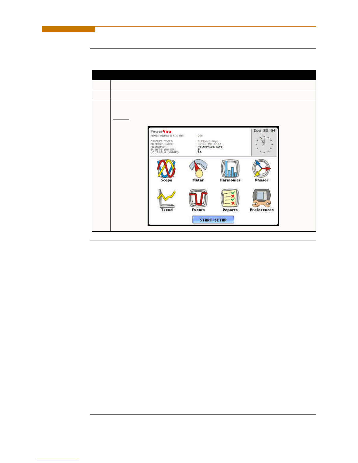
Home screen
features
Home screen is frequently referenced as the starting point for all major functionalities
of the PowerVisa.
The date and time appear on the top right corner of the Home screen. Both can be
configured to appear in a different format. See page 4-3 for the procedure on how to set
and reformat time and date.
The unit name and model, PowerVisa program revision level, and status messages
appear in the upper portion of the Home screen. Pertinent information that appear in the
status message area are the monitoring status, circuit configuration, percentage of data
card used while monitoring, site/file name, number of event cycles saved, and number
of timed intervals saved.
MONITORING STATUS: OFF indicates that the instrument is not actively
monitoring data. The monitoring status message will change to ON, DONE or
ARMED, depending upon the state of data monitoring. See page 5-25 for the
procedure on how to turn monitoring on/off.
Home screen contains the icons used to access the various PowerVisa functions. See
page
1-16 for the description of each icon found in Home screen.
1-15

Basic Operation, continued
Home screen
icons
Home screen contains the following icons used to access various PowerVisa functions:
Scope - Scope mode shows real-time voltage and current waveforms of the signals on
the measuring inputs. See Chapter 3 View Real Time Data - Section A Scope Mode.
Meter - Meter mode displays voltage and current measurements, along with other
calculated parameters. See Chapter 3 View Real Time Data - Section B Meter Mode.
Harmonics - Harmonic screen displays a spectral graph and textual matrix featuring the
amplitude and phase of each voltage and current harmonic to the 63rd harmonic. See
Chapter 3 View Real Time Data - Section C Harmonics.
Phasor - Phasor diagrams indicate phase relations between voltage and current based
upon the angles of the fundamental. See Chapter 3 View Real Time Data - Section D
Voltage and Current Phasor.
Preferences - Users can set instrument preferences like time and date, threshold alarm
feedback, language selection, communications, LCD display, and data card operation.
See Chapter 4 Instrument Settings.
Events - Events result in a contiguous collection of cycles that is recorded into memory.
Events are classified according to IEEE 1159, IEC 61000-4-30 Class A, and EN50160
standards. Events are displayed only after monitoring has been turned on or upon
reading a stored file from the data card. See Chapter 7 View Event Data - Section A
Events.
Trend - Trend allows users to view plots of journalled data along with min/max
measurements over the interval. See Chapter 7 View Event Data - Section B Trend.
Reports - The PowerVisa allows users to view two types of reports on QOS
compliance. EN50160 reports show graphs and statistical tables reflecting the
compliance of parameters specified according to EN50160 standard. Status shows a
quick status summary of Standard PQ, EN50160, and Motor Quality parameters using
the annunciator panel. The color coded panel indicates whether or not a parameter is
within limits. See Chapter 8 Reports.
Start/Setup - Users have the option to use Automatic Setup and proceed directly with
data monitoring or they can configure the instrument step-by-step using the Wizard
Setup. Users can also do Advanced setups to modify trigger parameters and intervals or
tweak threshold settings under the Advanced Setup Options. See Chapter 5 Start Menu
and Chapter 6 Advanced Setup Options.
1-16
 Loading...