

Page 1

E
NCORE
S
ERIES
®
61000 System
INSTALLATION GUIDE
DRANETZ - BMI
1000 New Durham Road
Edison, New Jersey 08818-4019
Page 2

WARNING
Death, serious injury, or fire hazard could result from improper connection of this instrument. Read and
understand this manual before connecting this instrument. Follow all installation and operating
instructio ns while using this instrument.
Connection of this instrument must be performed in compliance with the National Electrical Code (ANSI/
NFPA 70-2008) of USA and any additional safety requirements applicable to your installation.
Installation, operation, and maintenance of this instrument must be performed by qualified personnel
only. The National Electrical Code defines a qualified person as “one who has the skills and knowledge
related to the construction and operation of the electrical equipment and installations, and who has
received safety training on the hazards involved.”
Qualified personnel who work on or near exposed energized electrical conductors must follow applicable
safety related work practices and procedures including appropriate personal protective equipment in
compliance with the Standard for Electrical Safet y Re quirements for Employee Workplaces (ANSI/ NFPA
70E-2004) of USA and any additional workplace safety requirements applicable to your installation.
Published by Dranetz-BMI
1000 New Durham Road
Edison, NJ 08818-4019 USA
Telephone: 1-800-372-6832 or 732-287-3680
Fax: 732-248-1834
Web site: www.dranetz-bmi.com
Copyright ©2008 Dranetz-BMI
All rights reserved.
No part of this book may be reproduced, stored in a
retrieval system, or transcribed in any form or by any
means—electronic, mechanical, photocopying, recording,
or otherwise—without prior written permission from the
publisher, Dranetz-BMI, Edison, NJ 08818-4019.
Printed in the United States of America.
P/N UG-61000 Rev. D
ii
Page 3

ADVERTENCIA
U
na conexión incorrecta de este instrumento puede producir la muerte, lesiones graves y riesgo de incendio. Lea y
entienda este manual antes de conectar. Observe todas las instrucciones de instalación y operación durante el uso de
este instrumento.
La conexión de este instrumento a un sistema eléctrico se debe realizar en conformidad con el Código Eléctrico
Nacional (ANSI/NFPA 70-2008) de los E.E.U.U., además de cual qu ier otra norma de seguridad correspondiente a su
establecimiento.
La instalación, operación y mantenimiento de este instrumento debe ser realizada por personal calificado solamente.
El Código Eléctrico Nacional define a una persona calificada como "una que esté familiarizada con la construcción y
operación del equipo y con los riesgos involucrados."
El personal cualificado que trabaja encendido o acerca a los conductores eléctricos energizad os expuestos debe seg uir
prácticas y procedimientos relacionados seguridad aplicable del trabajo incluyendo el equipo protector personal
apropiado en conformidad con el estándar para los requisitos de seguridad eléctricos para los lugares de trabajo del
empleado (ANS I/NFPA 70E-2004) de los E.E.U.U. y cualqu ier requisito de seguridad adicional del lugar de traba j o
aplicable a su instalación.
AVERTISSEMENT
Si l'instrument est mal connecté, la mort, des blessures graves, ou un danger d'incendie peuvent s'en suivre. Lisez
attentivement ce manuel avant de connecter l'instrume nt. Lorsque vous utilisez l'instrument, suivez toutes les
instructions d'installation et de service.
Cet instrument doit être connecté conformément au National Electrical Code (ANSI/NFPA 70-2008) des Etats-Unis
et à toutes les exigences de sécurité applicables à votre installation.
Cet instrument doit être installé, ut ilisé et entretenu uniquement par un personnel quali fi é . Sel on le National
Electrical Code, une personne est qualifiée si "elle connaît bien la constructi on et l'utilisation de l'équipement, ainsi
que les dangers que cela implique".
Le personnel qualifié qui travaillent dessus ou s'approchent des conducteurs électriques activés exposés doit suivre
des pratiques en matière et des procédures reliées pa r sûreté applicable de travail comprenant le mat ériel de protection
personnel approprié conform é men t à la norme pour des conditions de sûreté électr iques pour les lieux de travail des
employés (ANSI/NFPA 70E-2004) des Etats-Unis et toutes les conditions de sûreté additionnelles de lieu de travail
applicables à votre installation.
WARNUNG
Der falsche Anschluß dieses Gerätes kann Tod, schwere Verletzungen oder Feuer verursachen. Bevor Sie dieses
Instrument anschließen, müssen Sie die Anleitung lesen und verstanden haben. Bei der Verwendung dieses
Instruments müssen alle Installation- und Betriebsanweisungen beachtet werden.
Der Anschluß dieses Instruments muß in Übereinstimmung mit den nationalen Bestimmungen für Elektrizität
(ANSI/NFPA 70-2008) der Vereinigten Staaten, sowie allen weiteren, in Ihrem Fall anwendbaren
Sicherheitsbestimmungen, vorgenommen werden.
Installation, B etrieb und Wart ung dieses Instruments dürf en nur von Fachpe rsonal durchg eführt werden . In dem
nationalen Bestimmungen für Elektrizität wird ein Fachmann als eine Person bezeichnet, welche "mit der Bauweise
und dem Betrieb des Gerätes sowie den dazugehörigen Gefahren vertraut ist."
Qualifiziertes Personal, das an bearbeiten oder her ausgestellte angezogene elektrische Leiter sich nähern, muß
anwendbare Sicherheit bezogener Arbeit Praxis und Verfahren einschließlich passende persönliche schützende
Ausrüstung gemäß dem Standard für elektrische Sicherheitsauflagen für Angestellt-Arbeitsplätze (ANSI/NFPA 70E-
2004) der Vereinigten Staaten und alle zusätzlichen Arbeitsplatzsicherheitsauflagen folgen, die auf Ihre Installation
anwendbar sind.
iii
Page 4
Safety Summary
Definitions
Symbols
Definiciones
WARNING statements inform the user that certain conditions or practices could result
in loss of life or physical harm.
CAUTION statements identify conditions or practices that could harm the 61000, its
data, other equipment, or property.
NOTE statements call attention to specific information.
The following International Electrotechnical Commission (IEC) symbols are marked
on the top and rear pa nel in the immediate vicinity of the refe ren ced terminal or device:
!
Las ADVERTENCIAS informan al usuario de ciertas condiciones o prácticas que
podrían producir lesiones mortales o daño físico.
Caution, refer to accompanying documents (this manual).
Alternating current (ac) operation of the terminal or device.
Direct current (DC) operation of the terminal or device.
Protective conductor terminal.
Símbolos
Las PRECAUCIONES identifican condici ones o prác tica s que podrí an dañar la 61000,
sus datos, otros equipos o propiedad.
Las NOTAS llaman la atención hacia la información específica.
Los siguientes símbolos de la Comisión Internacional Electrotécnica (IEC) aparecen
marcados en el panel superior y el posterior inmediatos al terminal o dispositivo en
referencia:
!
Precaución, consulte los documentos adjuntos (este manual).
OperaciÛn de corriente alterna (ca) del terminal o dispositivo.
Operación de corriente continua (CC) del terminal o dispositivo.
Terminal de proteccion del conductor.
iv
Page 5
Safety Summary,
Continued
Définitions
Symboles
Definitionen
Les messages d’AVERTISSEMENT préviennent l’utilisateur que certaines conditions
ou pratiques pourraient entraîner la mort ou des lésions corporelles.
Les messages de MISE EN GARDE signalent des condi ti ons ou pratiques susceptibles
d’endommager “61000”, ses données, d’autres équipements ou biens matériels.
Les messages NOTA attirent l’attention sur certains renseignements spécifiques.
Les symboles suivants de la Commission éle ctrotechniq ue intern ationale (CEI ) figurent
sur le panneau arrière supérieur situé à proximité du terminal ou de l’unité cité:
!
WARNUNGEN informieren den Benutzer darüber, daß bestimmte Bedingungen oder
Vorgehensweisen körperliche oder tödliche Verletzungen zur Folge haben können.
Mise en garde, consultez les documents d’accompagnement (ce manual).
Fonctionnement du terminal ou du dispositif sur le courant alternatif
(c.a.).
Fonctionnement du terminal ou de l’unité en courant continu (CC).
Borne conductrice de protecti on.
Symbole
VORSICHTSHINWEISE kennzeichnen Bedingungen oder Vorgehensweisen, die zu
einer Beschädigung von 61000, seiner Daten oder anderer Geräte bzw. von Eigentum
führen können.
HINWEISE machen auf bestimmte Informationen aufmerksam. Die folgenden
Symbole der Internationalen Elektrotechnischen Kommission (International
Electrotechnical Commission; IEC) befinden sich auf der Abdeck- und Seitenplatte
unmittelbar am betreffenden Terminal oder Gerät.
!
Vorsichtshinweis, siehe Begleitdokumente (dieses Handbuch).
Wechselstrombetrieb des Terminals bzw. Geräts.
Gleichstrombetrieb im Terminal oder Gerät.
Terminal-Schutzleiter.
v
Page 6

Safety Summary,
Continued
Safety
precautions
The following safety precautions must be followed whenever any type of voltage or
current connection is being made to the 61000.
• Connect the green safety (earth) ground first, before making any other connections.
• When connecting to electric circuits or pulse initiating equipment, open their related
breakers. DO NOT install any connection of the instrument on live power lines.
• Connections must be made to the instrument first, then connect to the circuit to be
monitored.
• Wear proper personal protective equipment, including safety glasses and insulated
gloves when making connections to power circuits.
• Hands, shoes and floor m ust be dry when making any connection to a power line.
• Make sure the unit is turned OFF before connecting probes to the rear panel.
• Before each use, inspect all cables for breaks or cracks in the insulation. Replace
immediately if defective.
• Pods should be connected first to the 61000, then connect to the circuit to be
monitored.
• If the equipment is used in a ma nner not specified in this user’s guide, th e pro tec tion
provided by the equipment may be impaired.
These safety precautions are repeated where appropriate throughout this manual.
vi
Page 7

Statements and Notices
Statement of
warranty
Statement of
reliability
Notice regarding
FCC compliance
All products of Dranet z-BMI are warranted to th e original pu rchaser against defective
material and workmanship for a period of one year from the date of delivery. DranetzBMI will repair or replace , at its opti on, all defec tive equ ipment that is returne d, freig ht
prepaid, during th e warrant y period. There wil l be no char ge for repair provided t here is
no evidence that the equi pment ha s been mishand led or ab used. Thi s warr anty s hall not
apply to any defects resulting from improper or inadequate maintenance, buyersupplied hardware/software interfacing, unauthorized modification or misuse of the
equipment, operation outside of environmental specifications, or improper site
preparation or maintenance.
The information in this m anual has be en reviewed and is believ ed to be entirely
reliable, however, no responsibility is assumed for any inaccuracies. All material is for
informational purposes only and is subject to change without prior notice.
This device has been tested and found to comply with the limits for a Class A digital
device, pursuant to Part 15 of the FCC Rules. These limits are designed to provide
reasonable prote cti on against harmful interfere nce when the equipment is operated in a
commercial environment. This equipment generates, uses, and can radiate radio
frequency energy and, if not installed and used in accordance with the instruction
manual, may cause harmful interference to radio communications. Operation of this
equipment in a residential are a is likel y to cause harmfu l inter feren ce in which cas e the
user will be required to correct the interference at his/her own expense.
Notice regarding
proprietary
rights
This publication contains information proprietary to Dranetz-BMI. By accepting and
using this manual, you agree that the information contained herein will be used solely
for the purpose of operating equipment of Dranetz-BMI.
Continued on next page
vii
Page 8

Statements and Notices,
Continued
Copyright
Trademarks
This publication is protected under the Copyright laws of the United States, Title 17 et
seq. No part of this p ublica tion may be rep roduced , tr ansmit ted, t ranscr ibed, s tored in a
retrieval system, or translated into any langua ge or computer language, in any form, by
any means, electronic, mechanical, magnetic, optical, chemical, manual, or otherwise,
without the prior written consent of Dranetz-BMI, 1000 New Durham Road, Edison,
New Jersey 08818.
Copyright ©2008 Dranetz-B MI
All Rights Reserved. Printed in the United States of America.
Encore Series Software, DataNode, Scope Mode, NodeLink and PQView are registered
trademar ks of Dranetz- BMI.
viii
Page 9

Table of Contents
Safety Summary .................................................................................................................... iv
Statements and Notices.......................................................................................................... vii
CHAPTER 1 - Introduction
About the 61000.................................................................................................................... 1-1
Unpacking the 61000.................................................................................. ......... .................. 1-3
61000 Accessories................................................................................................................. 1-4
Physical Description.............................................................................................................. 1-5
CHAPTER 2 - Controls, Indicators, and Connectors
External Components ............................................................................................................ 2-1
Connecting to AC Power Source........................................................................................... 2-6
Communications Interface..................................................................................................... 2-9
Input Module Connectors...................................................................................................... 2-11
Connecting Voltage Measurement Cables ............................................................................ 2-21
Connecting Current Probes.................................................................................................... 2-24
Connecting Voltage/Current Input Pods................................................................................ 2-28
Connecting Digital Input Connectors.................................................................................... 2-30
CHAPTER 3 - Circuit Diagrams for Power Monitoring
Connecting Power to the Voltage/Current Connections........................................................ 3-1
Single Phase........................................................................................................................... 3-6
Split Phase............................................................................................................................. 3-7
3 Phase, Four Wire Wye........................................................................................................ 3-8
3 Phase Delta............................................................................ ............................................. 3-9
3 Phase 2-Watt Delta............................................................................................................. 3-10
2 1/2 Element without Voltage Channel B............................................................................ 3-11
2 1/2 Element without Voltage Channel C............................................................................ 3-12
CHAPTER 4 - Operational Description
Input Settings......................................................................................................................... 4-1
Data Collection...................................................................................................................... 4-3
Memory Functions................................................................................................................. 4-4
Section A -External Communications Interface .......................................................................... 4-5
Remote Computer Operation................................................................................................. 4-5
Connection Setup via Modem............................................................................................... 4-6
Configuring the Encore 61000 DataNode for Modem Communication ............................... 4-7
Connection Setup via Com 1 RS232..................................................................................... 4-16
Connection Setup via GPS Antenna...................................................................................... 4-17
ix
Page 10

Table of Contents,
Section B -Local Operation.......................................................................................................... 4-18
Stand Alone Unit................................................................................................................... 4-18
Basic Operation ..................................................................................................................... 4-19
APPENDIX A - Optional Accessories
Introduction ........................................................................................................................... A-1
Hardware Accessories List.................................................................................................... A-2
Enclosure Hardware Options................................................................................................. A-5
Software Accessories............................................................................................................. A-19
APPENDIX B - Technical Specifications
General Specifications..................................................... ...................................................... B-1
Measurement Parameters....................................................................................................... B-4
Enclosure Ingress Protection Ratings.................................................................................... B-10
APPENDIX C - Connecting an External DC Power Supply
Introduction ........................................................................................................................... C-1
Connecting the DC Input Cable............................................................................................. C-2
Continued
APPENDIX D - Installing External Ferrite Clamps
Introduction ........................................................................................................................... D-1
Installation Procedure............................................................................................................ D-1
x
Page 11
Dranetz-BMI Encore Series® 61000 System
xi
Page 12

xii
Page 13

About the 61000; Unpacking the 61000; 61000 Accessories; Physical Description
About the 61000
61000
description
The Encore Series
world-class data acquisition products developed by Dranetz-BMI - the DataNode
family of products for the Signature System
integration of power measurement capabilities coupled with an innovative modular
design set the 61000 apart as a truly revolutionary product. The modular concept
applies to both the hardware configuration and firmware architecture allowing the unit
to be a multi-purpose instrument. 61000 works from being a diagnostic tool to
providing preventive and predictive information as an embedded solution. The
instrument is designed to operate either locally as a stand-alone unit with the optional
LCD panel installed or via remote comput er usin g the Enco re Serie s Software . 61000 is
compliant with IEEE1159, IEC61000-4-30 Class A, EN50160 standards, and more. It
can be installed in a permanent or semi-permanent installation.
C
HAPTER
Introduction
®
61000 System hereinafter referred to as 61000 encompasses two
®
and the PowerXplorer® PX5. This
1
Interface to
61000
Data
communication
61000 can operate locally as a stand-alone unit and/or remotely as a data acquisition
module connected to t he Encore Series Software:
Local operation with optional user interface
As a stand-alone unit, the 61000 can be outfitted with optional liquid crystal display
(LCD) as user interface. The optional touch screen display is mounted on the front
panel of the instrument (rack mount or switchgear mount). The LCD panel provides
immediate accessibility to monitoring all measurement parameters and instrument
setup and configurations. Refer to the 61000 User Interface Operations Guide for
detailed i nstructions.
Remote computer operation
The 61000 can operate as a data acquisition module connected to the Encore Series
Software. This software provides a centralized connection point for remote devices,
turning the computer into a self-contained web server. Encore Series Software permits
remote communications with th e 61000, with t he conve ntion al Inter net br owser a s user
interface. Remote operation includes instrument setup and configurations and
monitoring real-time par ameters, di sturbanc e and trend da ta. Refer to the Encore Ser ies
Software User’s Guide for detailed operating instructions.
61000 can communicate data to the Encore Series Software via Ethernet (wired,
wireless or fiber-optic based), RS485, and land/cellular modem via RS232. The
physical modem is an external option and is not included as part of the standard
product. This extends greater flexibility in the choice of communications interface for
remote operation.
Continued on next page
1-1
Page 14

About the 61000, continued
Input/Output
modules
Virtual analyzer
platform
61000 provides dedicated digital signal processing power via the separate and
independent connection for each input/output module installed. This modular and
configurable design shatters the traditional 8-channel (4 voltage, 4 current) instrument
format. Choose from the voltage, current, and data acquisition modules to build from
one to four instruments in a single, compact, cost-effective format. The available
modules are:
• AC Voltage Modules - 4 channels using either terminal block, safety jack, or 25-pin
connector to external voltage pods
• AC Current Modules - 4 channels for clamp-on CTs or 25-pin connector to external
CT pod
• Digital Input Modules - 8 channels
NOTE: The Modules are factory- inst alled . They cann ot be inst alle d in the fie ld and are
not user accessible.
See Chapter 2 Controls, Indicators and Connectors for more information on the input
modules. Chapter 3 Circuit Diagrams for Power Monitoring contains wiring diagrams
for when power measurements are to be made.
At the heart of the 61000 is the virtual analyzer platform or ‘instruments within an
instrument’ configuration. The virtual analyzer allows the instrument to distinguish
data operations in mul tiple modules. The user can confi gure up t o four vi rtual a nalyzers
per 61000 instrument.
This guide
The 61000 firmware architecture is based on the concept of separating the various
stages of acquisition, characterization, communications and visualization with clearly
defined interfaces that decouple one from the other. The instrument can monitor power
quality phenomena for troubleshooting and/or compliance purposes. It can record
inrush conditions, carry out long-term statistical studies to establish performance
baselines, and perfor m field-based equipment t esting and eval uation for commissionin g
and maintenance. The firmware inte grates intuit ive instrument setup procedures for
each module analyzer to ensure the capture of all relevant data for additional post
process analysis, report writing, and data archiving using other compatible DranetzBMI software applications such as PQView
®
.
This guide is only part of a complet e document set designed to provide comprehensive
information about the 61000. It primarily contains instructions on how to set up the
basic 61000 hardware for operation. It describes the input module interface and the
wiring configurati ons pos sible fo r volt age/c urr ent c onnect ion. It al so des cri bes t he dat a
communication ports availa ble in the backp lane of the ins trument. An overview on how
to set up the 61000 either as a stand-alone unit or as a data acquisition module
connected to the Encore Series Software is included in this guide.
For operational description using the local LCD panel, refer to the 61000 User
Interface Operations Guide (check with Dranetz-BMI for availability).
For operational description using remote communications via Encore Series Software,
refer to the Encore Series Software User’s Guide.
1-2
Page 15

Unpacking the 61000
Chapter 1/ Introduction
Unpacking
Shipping
damage
inspection
For maximum protection against possible shipping damage, the 61000 has been sealed
in a two-piece, plastic suspension pack, enclosed within a durable shipping carton.
After opening the carton, inspect the contents for possible shipping damage and check
the carton inventory.
Unpack the 61000 from the carton as follows:
Step Action
1 Remove any remaining literature inside the top of the carton.
2 Carefully remove the 61000 from its shipping carton.
3 Remove all accessories inside the carton. Check that the standard (see
page 1-4) and optional accessories (see Appendix A) you ordered are
included.
Visually inspect the 61000 for possible shipping damage. If any damage exists, first
notify and file an insurance claim with your carrier or underwriter or both. Then noti fy
Dranetz-BMI Customer Service Department of your intentions to return the unit. DO
NOT return the 61000 without prior instructions from Dranetz-BMI Customer Service
Department. Dranetz-BMI Customer Service Department can be reached at (732) 2873680 or 1-800-372-6832.
Repacking for
return shipment
Return notice
If the unit must be return ed to Dranetz -BMI for servi ce or repai r , wrap the unit sec urely
in heavy packaging mater ial and place in a well padded box or crate to p revent damag e.
Do not return the 61000 in an unpadded box. Dranetz-BMI will not be responsible for
damage incurred during transit due to inadequate packing on your part.
Notify Dranetz-BMI Customer Service of your intention of returning the unit. Do not
return the unit without prior instructions from Dranetz-BMI. Dranetz-B MI Customer
Service Department can be reached at (732) 287-3680 or 1-800-372-6832.
1-3
Page 16

61000 Accessories
61000 Accessories
Standard
accessories
Optional
accessories
Technical
specifications
External dc
power source
Calibration
The standard accessory included with the 61000 is the Encore Series 61000 System
Installation Guide, P/N UG-61000.
Refer to Appendix A for the list of hardware and software optional accessories
available for use with 61000. The unit mainframe can be custom-built with optional
input module connecto rs, co mmunica tion port c onne ctors , GPS ant enna co nnec tor, and
a 12V dc power input jack.
Specifications for the 61000 measured parameters, computed parameters, voltage
modules, current probes, and pod accessories are listed in Appendix B.
To connect to an external dc power source, refer to Appendix C.
The recommended calibration interval for this unit is once every 12 months.
We recommend that you return the unit to the factory for calibration. If you decide to
do so, first contact the Dranetz-BMI Customer Service Department to obtain an
Authoriz ation Number.
Telephone: (732) 287-3680 or 1-800-372-6832
Fax: (732) 248-9240
Fill out the Repair /Servi ce Ord er for m enclos ed in the shippi ng car ton and ship i t alon g
with the unit to the Dranetz-BMI Repair Department. (If this form is missing, ask the
Dranetz-BMI Customer Service Department for a replacement.)
1-4
Page 17

Physical Description
Chapter 1/ Introduction
Dimensions
Optional display
panel
Connector panel
External dc
power source
The 61000 in the desktop e ncl os ure without the optional LCD panel is a self -contained
instrument weighing 4 pounds and measuring 11.25” width x 3.5” height x 7 3/4”
depth.
When used with the LCD panel installed in 19” rack, the instrument weighs 5 pounds
and has an 8” depth.
When used with the LCD panel installed in switchgear mounting enclosure, the
instrument weighs 10 pounds and measures 7” width x 6.5” height x 8” depth.
The optional user interf ace is a 1/4 VGA LCD panel with touch screen menus for l oca l
operation and configuration.
The backplane panel consists of industrial grade, voltage/current/pod connectors,
communication port connectors, dc input power connector, and power switch. See
Chapter 2 Controls, Indicators and Connectors for description.
To connect to an external dc power source, refer to Appendix C.
1-5
Page 18

This page intentionally left blank.
1-6
Page 19
Controls, Indicators, and Connectors
External Components; Connecting to AC Power Source; Communications Interface;
Input Module Connectors; Connecting Voltage Measurement Cables; Connecting
Current Probes; Connecting Voltage/Current Input Pods; Connecting Digital Input
Connectors
External Components
C
HAPTER
2
Description
Front panel
External components refer to operator related external controls, indicators and
connectors.
The 61000 front panel display may look different depending on the enclosure options
specified.
Front panel without the local LCD User Interface
See below for description of the 61000 front display without the LCD user interface.
SF-201
Part Function
1 Sta tus Indicator. LED will l ig ht steadily when abnormal condition is dete ct ed.
The unit is operating normally when light is off.
2 Monitoring On. LED will light if monitoring is on. Monitoring status is off
when light is off.
3 Power Indi ca tor. LED will blink when the unit power switch is turned on. The
number of blinks correspond to the number of modules installed.
Continued on next page
2-1
Page 20
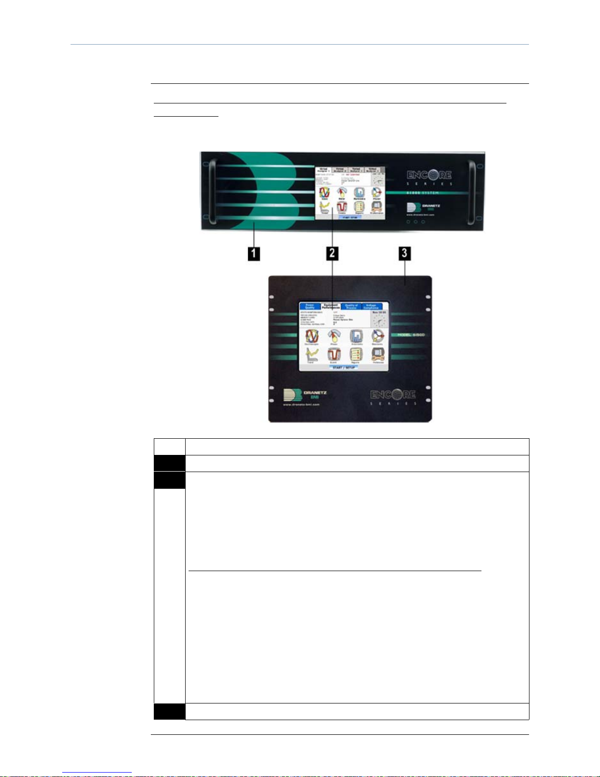
External Components, continued
Front panel
(continued)
Front panel with the optional LCD User Interface in Rack Mount and Switchgear
Mount Display
The front view primarily shows the color touch screen LCD. See below for descr ip ti on
of the 61000 front display with the LCD panel installed.
SF-202d
Part Function
1 LCD Rack Mount Protective Enclosure with rack handles
2 Liquid Crystal Display (LCD). Provides 3.75 x 4.75 inches display consisting
of 1/4 VGA size screen of text and graphic information. The color LCD is
equipped with touch screen technology, operable using the finger and/or
stylus. Touch screen display permits menu sel ection, alphanumeric data entry,
and has a compact fluorescent (CCFL) backlighting that is on for low light
level viewing.
The following are some basic care instructions for the LCD monitor
:
• Use and store the unit within the specified temperature and humidi ty range.
The LCD screen may be adversely affec ted by exposure to high temperat ure
or humidity. Condensation or moisture produced by sudden temperature
changes may also damage the LCD screen. Clean any moisture from su rface
immediately.
• Be careful when cleaning or removing stains on the LCD surface. Gently
wipe the surface with a soft cloth or cotton pad. Isopropyl alcohol may be
used, but make sure that all solvent residue is removed.
• Do not apply exces si ve f o rc e t o the LCD surface. The LCD screen contains
sensitive electronic components that may be damaged due to strong impact.
3 LCD Switchgear Mount Enclosure
2-2
Page 21
Chapter 2/ Controls, Indicators, and Connectors
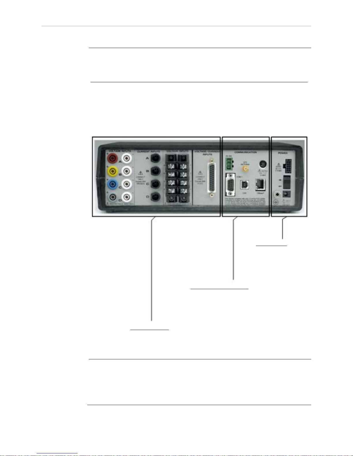
Rear panel
As with the front panel, the 61000 rear panel display may also vary depending on the
input module/s installed.
Rear Panel for 61STD Unit - Configurable to Up to Four Input Module Combinations
61000 Standard (61STD) can accommodate up to four input modules with different
types of connectors. The modules installed on the rear panel are customized based on
user specifications. The rear panel consists of the input module connectors,
communication ports, and power switch. See below for description of a typical 61000
rear panel. Exact configuration is dependent on the optional input modules
ordered.
SF-203
Important
Power Input
See Connecting to AC Power
Source, page 2-7 on how to
power the unit on/off
Communications Ports
See Communications Interface,
page 2-10 for a description of the
61000 data ports
Input Modules
See Input Module Connect ors, page 2-15
for a detailed description of the input
module connectors for 61STD
Dranetz-BMI recommends that you leave adequate working space for rear panel
connections to the 61000. This rear clearance space is necessary for proper installation
of the measurement cables, pr obes and pods as wel l as extern al communic ations device
for the 61000.
Continued on next page
2-3
Page 22
External Components, continued
Rear panel
(continued)
Rear Panel for 61VCM Unit - Single Module Unit
61000 Voltage Compliance Monitor (61VCM) is a single module unit designed to
interface with the AC/DC Voltage Module with terminal block connectors (61MVS).
The 61VCM rear panel has built-in terminal block connectors to connect the voltage
input module. The communication ports and power switch are similar to that of the
61000 Standard uni t. See below for description of t he 61VCM re ar panel as configured
for use in a 61VENCL.
SF-203b
Input Modules
See Input Module Connectors, pag e 2-18
for a detailed description of the input
module connectors for 61VCM
Power Input
See Connecting to AC Power
Source, page 2-7 on how to
power the unit on/off
Communications Ports
See Communications Interface,
page 2-10 for a description of the
61000 data ports
Continued on next page
2-4
Page 23
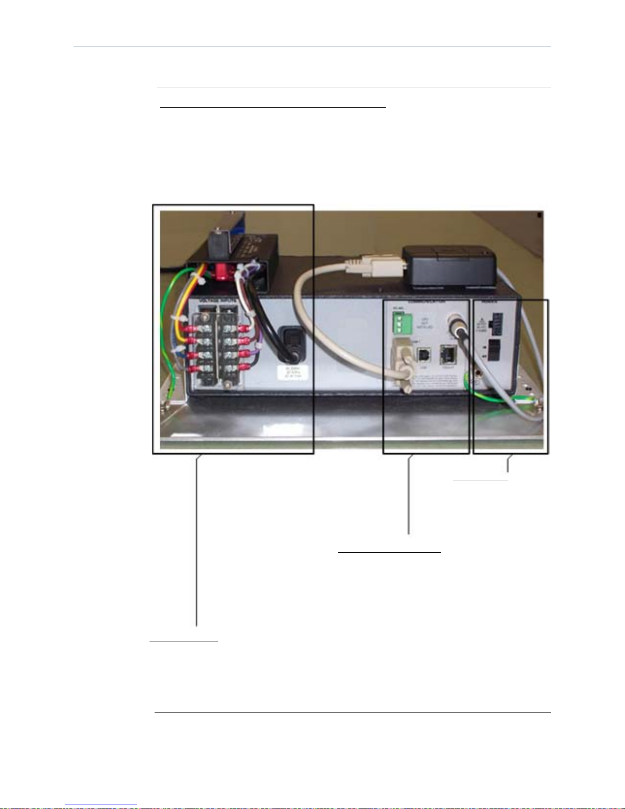
Chapter 2/ Controls, Indicators, and Connectors
Rear panel
(continued)
Rear Panel for 61SGD and 61SG Units - Switchgear Mounting Units
The 61SGD and 61SGD monitor (henceforth referred to as 61SGD in this section) is
similar in functionality to the 61RMTD and 61RMT respectively, except that they are
designed to be mounted into a switchgear enclosure, rather than a 19" rack, and the
power supply inputs are different. All of the same input module options and
communication options of the 61STD and 61RMTD are applicable. The power supply
inputs are designed for 90-250Vac, 50/60Hz, or 105-125Vdc. A screw terminal strip is
used to connect the appropriate gauge wire for the application. The positive and
negative inputs are fused wit h use r -repl aceab le fuse s of th e same type as provided with
the product. See below for description of the 61SGD rear panel as configured with
three modules.
Input Modules
See Input Module Connectors,
page 2-15 for a detailed descrip tion
of the input modul e c onnect ors f or
61SGD
Optional
enclosures
Optional enclosures for 61STD, 61RMTD, 61RMT, 61SG, 61SGD, 61VENCL,
61WENCL and 61VCM are available in Dranetz-BMI. See Appendix A Optional
Acessories - Enclosure Hardware Options for details.
Communications Ports
See Communications Inter face,
page 2-10 for a description of
the 61000 data ports
SF-203d
Power Input
See Connecting to 90-250Vac/
105-125Vdc Power Source,
page 2-7 on how to power the
unit on/off
2-5
Page 24

Connecting to AC Power Source
Connecting to AC Power Source
Power
specifications
The 61000 AC adapter can be connected to a 90-265Vac power input source
(dependent on model version) or directly to a 12Vdc external power source. Refer to
Appendix C for information about connecting to an external dc power source.
CAUTION Always set the power switch to the off position befor e connecting or disconnecting
the input power cable.
Operation of the 61000 from an ac voltage source other than the rated voltage
input stated on the unit nameplate can cause damage to the unit.
PRECAUCION Siempre fije el inter ruptor de encendido en la posic ión apagada antes de conect ar
o desconectar el cable de energía de entrada.
La operación del 61000 desde una fuen te de volt aje de ca que no sea la e ntrada d e
voltaje nominal indicada en la placa de identificación de la unidad puede causar
daños a la unidad.
MISE EN
GARDE
Mettez toujours l’interrupteur dans la position ouverte avant de connecter ou de
déconnecter le câble d’alimentation primaire.
Mettez toujours l’interrupteur dans la position ouverte avant de connecter ou de
déconnecter le câble d’alimentation primaire.
VORSICHT Vor dem Einstecken bzw. Ausstecken des Eingangsnetzkabels den Netzschalter
immer in die Aus-Stellung bringen.
Der Betrieb des 61000 von einer Wechselspannungsquelle, die nicht dem auf der
Namensplatte der Einheit aufgeführten Nennspannungseingang entspricht, kann
zur Beschädigung der Einheit führen.
2-6
Page 25
Chapter 2/ Controls, Indicators, and Connectors
Power input/
switch diagram
The power switch panel includes LED indicators, On/Off power switch, power input
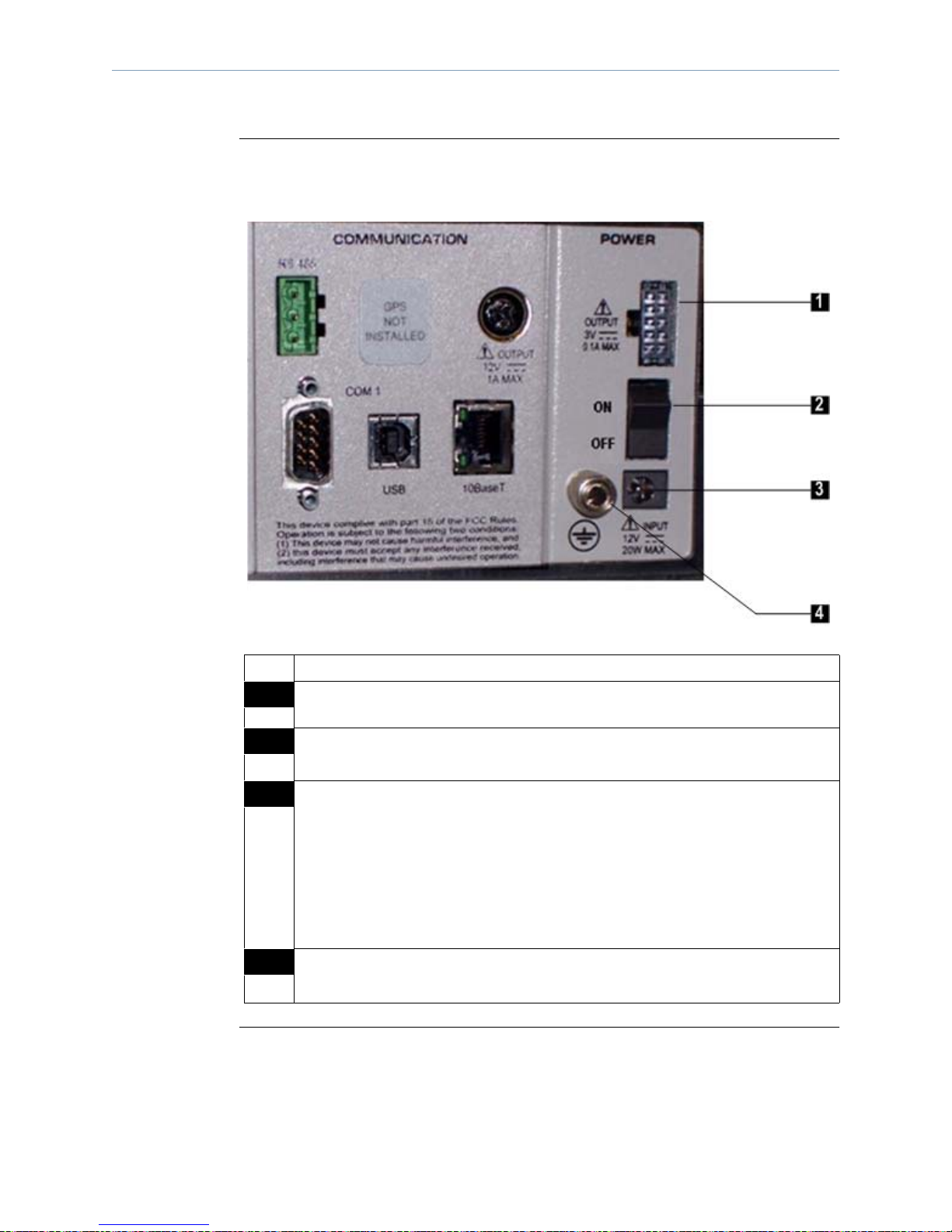
decal and connector. See actual photo and description of power switch below.
SF-204
Part Function
1 Output Power for Flex Probes. Requires cable DC3VFLEX (P/N 117067-G1).
2 ON/OFF Power Switch. Push for on, push for off.
3 Power input decal and connector. The decal provides information about input
power rating. Plug in the AC Adapter output cable into the input connector.
AC input power source is specified as follows:
• Voltage range, 120/230V ac.
• Frequency, 50/60Hz.
• Power Consumption, 20W.
See page 2-8 for the procedure on how to connect to an ac power source.
4 Ground LUG. Connect with suitable wire to earth ground conductor or
connector.
2-7
Page 26

Connecting to AC Power Source
Connecting to
an AC power
source
Safety
Disconnects
For 61000 Standard (61STD) and Single Module (61VCM) Units
Follow these steps to connect to an ac power source
.
Step Action
1 Set the power switch to OFF.
2 Verify the operating voltage range for your 61000, as marked on the
power input decal.
3 Connect the appropriate power cord for the voltage rating of the unit.
Make connection to the instrument first.
4 Connect power cord to the power source.
5 Turn power switch to ON.
For Switchgear (61SG and 61SGD) Mounting Units
The mains supply power to the Encore Series 61SG or SGD must be installed
downstream from a switched cu rr ent limiti ng device. The cir cuit pr otect ion device
should be 20 Amps or less, and must be rated for the available voltage and fault
current; 5 Amps fuses are preferred.
WARNING
All mains supply conductors connected to the Encore Series 61SG or SGD must
originate at circuit breakers or fuses rated 20 Amps or less.
You must provide a method f or man uall y removing power from the Encor e Ser ie s
61SG or 61SGD such as a clearly labeled circuit breaker or a fused disconnect
switch.
Step Action
1 With all power OFF, connect the green ground wire to Safety (Earth)
ground first before making any other connections.
2 Connect the positive (+) terminal of the mains supply to the positive (+)
terminal of the instrument.
3 Connect the negative (-) terminal of the mains sup ply to the negative (-)
terminal of the instrument.
4 Turn power switch to disconnect device to ON.
5 Turn power switch of the instrument to ON position.
2-8
Page 27

Communications Interface
Chapter 2/ Controls, Indicators, and Connectors
Communications
options
The 61000 can communicate to a computer via Ethernet network, RS232, RS485, or
land/cellular modem. This remote communication network enables the 61000 to act as
a DataNode for the Encore Series Software, or as a stand-alone monitor.
Computer
requirem ents
The computer used must be equipped with the same communication interface as the
61000. For example, if the instr ument is using Ethernet , the comput er must li kewise be
using Ethernet.
The computer must be loaded wit h the Encore Seri es Software package, which conve rts
the computer into a web server and enables it to browse data and information col le ct ed
by the 61000.
WARNING To avoid the risk of electric shock, do not remove communications instrument
until all power is de-energized to all power and measurement circuits.
ADVERTENCIA
Para evitar el riesgo de descargas eléctricas, no retire el instrumento de
comunicaciones hasta desconectar todo suministro de energía hacia todos los
circuitos de energía y medición.
AVERTISSEMENT
Pour éviter le risque de choc électrique, ne retirez pas le instrument de
communications avant que tous les circuits d’alimentation et de mesure aient été
mis hors tension.
WARNUNG Zur Vermeidung eines elektrischen Schlags die Kommunikationsplatte erst
instrument, wenn die Stromzufuhr zu allen Strom- und Meßschaltungen
unterbrochen wurde.
Remote
operation guide
Remote operation setup and instructions for 61000 are contained in the Encore Series
Software User’s Guide.
2-9
Page 28
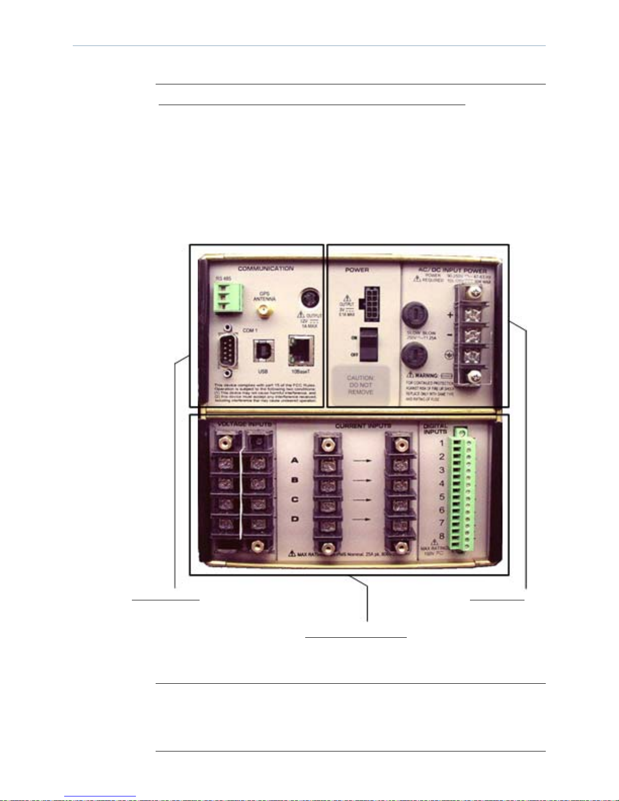
Communications Interface
Communication
port diagram
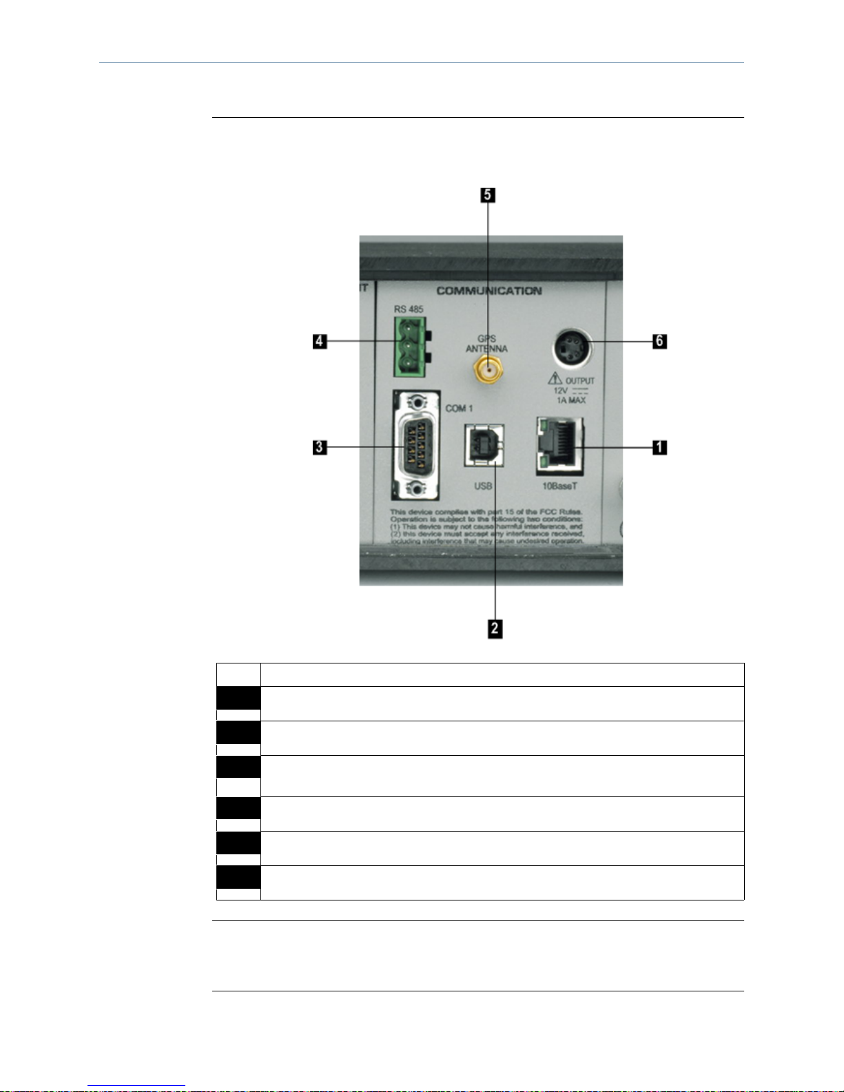
The communications panel shows the location of data ports available in 61000. Actual
photo and description of communications panel are shown below.
Parts table
Remote
operation guide
SF-205
Part Function
1 10/100BaseT (RJ45). Allows connection via Ethernet cable.
2 USB. Not activate d at this time; future option.
3 COM 1. RS232 serial port for land/cellular modem connection. Allows
administrative set up of the 61000 for IP addressing, etc.
4 RS485 serial port. Can be used for multi-drop serial connections.
5 Optional GPS Antenna. Allows use of optional cable to active antenna.
6 Power Connector for External GM28/29 Modem.
See Chapter 4 Operat ional Descr ipti on for a discu ssion of th e e xtern al co mmunica tions
device and software applications necessary for remote computer operation of 61000.
2-10
Page 29

Input Module Connectors
Chapter 2/ Controls, Indicators, and Connectors
Input modules
for 61STD and
61SGD
Input module
for 61VCM
Users can choose different types of analog and digital input modules that can be
installed on the rear panel of the 61000 Standard (61STD) and 61000 Switchgear
(61SGD) units. The modules must be selected at time of order. In case users want
additional modules installed, the unit must be returned to the factory. The input
modules allow a variety of voltage and current measurement cables, probe types, or
pods to connect to the instrument for voltage, current, and/or digital signal monitoring.
The voltage and current connectors are designed in modular configuration, with the
following analog input module measurement point interface:
• AC/DC Voltage Module with safety connectors (Model 61MVB)
• AC/DC Voltage Module with terminal block connectors (Model 61MVS)
• AC/DC Current Module with connectors for external CTs (Model 61MAC )
• AC/DC Module for Voltage or Current Pod (Model 61MZP)
The eight-channel digital input module Model 61MDIN allows users to monitor on/of f
type digital signals, such as breaker or switch signal positions. Digital inputs can be
configured to provide de mand interval syn chronizatio n, pulse counting , KYZ metering,
or to provide start/stop monitoring control.
61000 Voltage Compliance Monitor unit (61VCM) offers only one type of module
interface:
Input channels
• AC/DC Voltage Module with terminal block connectors (Model 61MVS)
The module connectors for 61VCM is factory installed and cannot be altered by users.
Input channels for the modules installed on the rear connector panel are labelled ±A,
±B, ±C, and ±D. You must turn on any input channel to be used for monitoring. If a
channel is not turned on, no data will be collected for it.
Continued on next page
2-11
Page 30

Input Module Connectors
WARNING Death, serious injury, or fire hazard could res ult fr om imprope r connectio n of this
instrument. Read and understand this manual before connecting this instrument.
Follow all installation and operating instructions while using this instrument.
Connection of this instrument must be performed in compliance with t he National
Electrical Code (ANSI/NFPA 70-2008) and any additional safety requirements
applicable to your installation.
Installation, operation, and maint enance of this ins trument must be perfor med by
qualified personnel only. The National Electrical Code defines a qualified person
as “one who has the skills and knowledge related to the construction and
operation of the electrical equipment and installations, and who has received
safety training on the hazards involved.”
Qualified personnel who work on or near exposed energized electrical conductor s
must follow applicable safety related work practices and procedures including
appropriate personal protective equipment in compliance with the Standard for
Electrical Safety Requ ireme nts for Employe e W orkplac es (ANSI/NFPA 70E-2004)
of USA and any additional workplace safety requirements applicable to your
installation.
ADVERTENCIA
Una conexión incorrecta de este instrumento puede producir la muerte, lesiones
graves y riesgo de incendio. Lea y enti enda este manual antes de conectar. Observe
todas las instrucciones de instalación y operación durante el uso de este
instrumento.
La conexión de este instrumento a un sistema eléctrico se debe realizar en
conformidad con el Código Eléctrico Nacional (ANSI/NFPA 70-2008) de los
E.E.U.U., además de cualquier otra norma de seguridad correspondiente a su
establecimiento.
La instalación, operación y mantenimiento de este instrumento debe ser realizada
por personal calificado solamente. El Código Eléctrico Nacional define a una
persona calificada como "una que esté familiarizada con la construcción y
operación del equipo y con los riesgos involucrados."
El personal cualificado que trabaja encendido o acerca a los conductores
eléctricos energizados expuestos debe seguir prácticas y procedimientos
relacionados seguridad aplicable del trabajo incluyendo el equipo protector
personal apropiado en conformidad con el estándar para los requisitos de
seguridad eléctricos para los lugares de trabajo del empleado (ANSI/NFPA 70E-
2004) de los E.E.U.U. y cualquier requisito de seguridad adicional del lugar de
trabajo aplicable a su instalación.
2-12
Continued on next page
Page 31

A
VERTISSEMENT
Chapter 2/ Controls, Indicators, and Connectors
Si l'instrument est mal connecté, la mort, des blessures graves, ou un danger
d'incendie peuvent s'en suivre. Lisez attentivement ce manuel avant de connecter
l'instrument. Lorsque vous utilisez l'instrument, suivez toutes les instructions
d'installation et de service.
Cet instrument doit être connecté conformément au National Electrical Code
(ANSI/NFPA 70-2008) des Etats-Unis et à toutes les exigences de sécurité
applicables à votre installation.
Cet instrument doit être inst allé, util isé et entre tenu uniquement par un perso nnel
qualifié. Selon le National Electrical Code, une personne est qualifiée si "elle
connaît bien la construction et l'utilisation de l'équipement, ainsi que les dangers
que cela implique".
Le personnel qualifié qui travaillent dessus ou s'approchent des conducteurs
électriques activés exposés doit suivre des pratiques en matière et des procédures
reliées par sûreté applicable de travail comprenant le matériel de protection
personnel approprié conformément à la norme pour des conditions de sûreté
électriques pour les lieux de travail des employés (ANSI/NFPA 70E-2004) des
Etats-Unis et toutes les conditions de sûreté additionnelles de lieu de travail
applicables à votre installation.
WARNUNG Der falsche Anschluß dieses Gerätes kann Tod, schwere Verletzungen oder Feuer
verursachen. Bevor Sie dieses Instrument anschließen, müssen Sie die Anleitung
lesen und verstanden haben. Bei der Verwendung dieses Instruments müssen alle
Installation- und Betriebsanweisungen beachtet werden.
Der Anschluß dieses Instruments muß in Übereinstimmung mit den nationalen
Bestimmungen für Elektrizität (ANSI/NFPA 70-2008) der Vereinigten Staaten,
sowie allen weiteren, in Ihrem Fall anwendbaren Sicherheitsbestimmungen,
vorgenommen werden.
Installation, Betrieb und Wartung dieses Instruments dürfen nur von
Fachpersonal durchgeführt werden. In dem nationalen Bestimmungen für
Elektrizität wird ein Fachmann als eine Person bezeichnet, welche "mit der
Bauweise und dem Betrieb des Gerätes sowie den dazugehörigen Gefahren
vertraut ist."
Qualifiziertes Personal, das an bearbeiten oder herausgestellte angezogene
elektrische Leiter sich nähern, muß anwendbare Sicherheit bezogener Arbeit
Praxis und Verfahren einschl ie ßli ch passende persönliche schützende Ausrüstung
gemäß dem Standard für elektrische Sicherheitsauflagen für AngestelltArbeitsplätze (ANSI/NFPA 70E-2004) der Vereinigten Staaten und alle
zusätzlichen Arbeitsplatzsicherheitsauflagen folgen, die auf Ihre Installation
anwendbar sind.
Continued on next page
2-13
Page 32

Input Module Connectors, continued
Safety
precautions
The following safety precautions must be followed whenever any type of voltage or
current connection is being made to the 61000.
• Connect the green safety (earth) ground first, before making any other connections.
• When connecting to electric circuits or pulse initiating equipment, open their related
breakers. DO NOT install any connection of the instrument on live power lines.
• Connections must be made to the instrument first, then connect to the circuit to be
monitored.
• Wear proper personal protective equipment, including safety glasses and insulated
gloves when making connections to power circuits.
• Hands, shoes and floor m ust be dry when making any connection to a power line.
• Make sure the unit is turned OFF before connecting probes to the rear panel.
• Before each use, inspect all cables for breaks or cracks in the insulation. Replace
immediately if defective.
• Pods should be connected first to the 61000, then connect to the circuit to be
monitored.
• If the equipment is used in a ma nner not specified in this user’s guide, th e pro tec tion
provided by the equipment may be impaired.
2-14
Page 33

Chapter 2/ Controls, Indicators, and Connectors
Module
connectors
diagram for
61STD and 61SGD
The 61STD and 61SGD units can accommodate up to four input/output modules with
different types of connectors. The modules installed on the rear panel are customized
based on user specifications. The following pages describe how the optional voltage
and current measurement cables , probes a nd pod acce ssori es can co nnec t to th e 61STD
or 61SGD for circuit monitoring.
The photo below shows the 61000 rear panel with four types of analog input module
connectors. Digital input module connectors are also available (see Appendix A
Optional Accessories) but not shown in photo.
1.1
1.3
1.5
1
1.2
2.1
3.1
1.4
2.2
3.3
1.6
2.3
3.5
3
SF-206
3.2
4.1
3.4
3.6
Parts table
1.7
1.8
3.7
2.4
3.8
2 4
Part Function
1 AC Voltage Module with Safety Jack Connectors (Model 61MVB)
1.1 CH A, + Differential Voltage Input Connector; color red
1.2 CH A, - Differential Voltage Input Connector; color white
1.3 CH B, + Differential Voltage Input Connector; color yellow
1.4 CH B, - Differential Voltage Input Connector; color white
1.5 CH C, + Differential Voltage Input Connector; color blue
1.6 CH C, - Differential Voltage Input Connector; color white
1.7 CH D, + Differential Voltage Input Connector; color grey
1.8 CH D, - Differential Voltage Input Connector; color white
Continued on next page
2-15
Page 34

Input Module Connectors, continued
Parts
(continued)
Part Function
2 AC Current Module with Connectors for External CTs (Model 61MAC)
2.1 CH A, PROBE, Current Input Connector
2.2 CH B, PROBE, Current Input Connector
2.3 CH C, PROBE, Current Input Connector
2.4 CH D, PROBE, Current Input Connector
3 AC Voltage Module with Terminal Block Connectors (Model 61MVS)
3.1 CH A, + Differential Voltage Input Connector
3.2 CH A, - Differential Voltage Input Connector
3.3 CH B, + Differential Voltage Input Connector
3.4 CH B, - Differential Voltage Input Connector
3.5 CH C, + Differential Voltage Input Connector
3.6 CH C, - Differential Voltage Input Connector
3.7 CH D, + Differential Voltage Input Connector
Measurement
cables, probes
and pods
3.8 CH D, - Differential Voltage Input Connector
4 AC Voltage/Current Module with 25-PIN DConnector (Model 61MZP)
4.1 25-PIN DConnector
Digital Input Module (Model 61MDIN) is also available as input module option. See
page 2-30 for information on digital input connections.
The input modules and the cables, probes and pods that connect to it are optional
accessories listed in Appendix A Optional Accessories.
Voltage Measurement Cables (for Voltage Input Module with safety jack connectors Model 61MVB): Voltage measurement cables are stored in a cable pouch as part of the
measurement cable set , P/ N 116042-G3. Each cable set consi sts of a ca ble an d alli ga tor
clip. Each alligator clip has an insulated safety grip. Red alligator clips are used for
connection to the line connection (+) of voltage channels A, B, C, and D. Black
alligator clips are used for the neutral or return line connection (-). See page 2-21 for
more information voltage cable connections.
Current Probes (for Current Input Module - Model 61MAC)
: A variety of current
cables and probes are available for connecting Channels A, B, C, and D to the current
input jack. Typical current probes are illustrated on page 2-25.
2-16
Continued on next page
Page 35

Chapter 2/ Controls, Indicators, and Connectors
Measurement
cables, probes
and pods
(continued)
Voltage/Current Pods (for Voltage/Current Input Module - Model 61MZP)
: Connects to
the Series 5500 Voltage/Current input module via the 25-PIN interf ace cable connector
on the rear panel of the instrument. See page 2-28 for more information on voltage/
current input pod connection.
The next pages describe the possible voltage and current assembly connections to the
input connectors in the rear panel of 61000.
NOTE:
VOLTAGE AND CURRENT PROBES ARE NOT SHOWN CONNECTED TO
THE SPECIFIC INPUT MODULES IN THE CONNECTION DIAGRAMS
PROVIDED BECAUSE THE ACTUAL VOLTAGE CABLE AND CURRENT
PROBES USED ARE DEPENDENT ON THE TYPE OF INPUT MODULES
AND OPTIONAL ACCESSORIES PURCHASED.
See Chapter 3 Circuit Diagrams for Power Monitoring for the wiring connection
diagrams to set up the instrument for monitoring.
2-17
Page 36

Input Module Connectors, continued
Module
connectors
diagram for
61VCM
Actual photo below shows the rear panel of the 61000 Voltage Compliance Monitor
unit (61VCM). The voltage input module is shown configured for installation in the
61VENCL optional enclosure.
Parts table
Part Function
1 Terminal Block Assembly for 61VENCL
2 Wiring from Terminal Block Assembly to Voltage Module
3 Terminal Block Assembly Ground Wire (attach to mounting plate w/ screw)
4 Voltage Input Module with Terminal Block Connectors
4.1 CH A, + Differential Voltage Input Connector, R ed
4.2 CH A, - Differential Voltage Input Connector, White
2-18
Continued on next page
Page 37

Parts table
(continued)
Chapter 2/ Controls, Indicators, and Connectors
Part Function
4.3 CH B, + Differential Voltage Input Connector, Yellow
4.4 CH B, - Differential Voltage Input Connector, Brown
4.5 CH C, + Differential Voltage Input Connector, Blue
4.6 CH C, - Differential Voltage Input Connector, Violet
4.7 CH D, + Differential Voltage Input Connector, Gray
4.8 CH D, - Differential Voltage Input Connector, Black
5 Power Cord from Terminal Block Assem bly connects to AC Receptacle in
61VCM unit
2-19
Page 38

Input Module Connectors, continued
Wiring
connectors
The photo and diagram below show wiring connection for terminal strip to voltage
input module connectors on 61VCM unit when installed in the 61VENCL.
Terminal strip housed inside the terminal block assembly
Wiring detail from terminal strip to voltage connectors on real panel of 61VCM
2-20
Page 39

Chapter 2/ Controls, Indicators, and Connectors
Connecting Voltage Measurement Cables
Measurement
cable set
Optional cable
set for 61MVB
Description
: Voltage measurement cables or customer-supplied wiring are used as
connectors for Voltage input modules with safety jack or terminal block connectors,
respectively.
Voltage Rating
: Direct connection of all voltage measurement cables are rated at 600
Vrms max. For measur ing vol tages gr eate r than 600 Vrms, potential transfo rmers (PT s)
must be used. Any customer-supplied wiring should be UL-listed for 600 Vrms
minimum for inputs rated 600 Vrms max and 1000 V minimum for inputs rated 1000 V
max.
Description
: A voltage measurement cable set, P/N 116042-G1, is available as an
optional accessory to be used with the 61MVB Voltage Module.
Contents
: The voltage measurement cables are shown on page 2-22. A cable set
consists of eight, 6-foot channel measurement cable assemblies (probes), each with a
detachable, alligator jaw, safety clip assembly (maximum jaw opening, 3/4 in (20
mm)). The safety clip assemblie s are red (+) and black (-) for each of the four channe ls.
One cable each of red (channel A), yellow (channel B), blue (channel C), and grey
(channel D), and four each of white are provided.
A pouch for storage of the cables is included in the contents of the measurement cable
set, but is not shown in the figure.
Optional fused
voltage adapter
There are two optional fuse accessory kits available for use with the measurement
cables. One kit (P/N FVA-1) contains one fused voltage adapter and one measurement
connecting Red cable 50 cm i n lengt h. The othe r kit ( P/N FVA-4) contains four voltage
adapters and four measurement connecting cables 50 cm in length (one Red, one
Yellow, one Blue, and one Grey).
The single fuse voltage adapter kit is used for one single voltage measurement input.
While the four fuse voltage adapter kit is used for a three phase and neutral voltage
measurement inputs. If these fuse kits are not used, i t i s recommended that the user use
terminal strips to fused circuits, preferably with local disconnects.
Continued on next page
2-21
Page 40

Connecting Voltage Measurement Cables, continued
Measurement
cable set wi th
optional fuse
diagram
WARNING
WARNING
WARNING
NOTE: 2 FT CABLE
INCLUDED WITH
FUSE VOLTAGE
ADAPTER
OPTIONAL
FUSE
VOLTAGE
ADAPTER
OPTIONAL
FUSE
VOLTAGE
ADAPTER
OPTIONAL
FUSE
VOLTAGE
ADAPTER
OPTIONAL
FUSE
VOLTAGE
ADAPTER
A+ B+ C+ D+ A- B- C- D-
To AC Voltage Module with safety jack
SF-207
or terminal block connectors
To avoid the risk of electric shock or burns, always connect the safety (or earth)
ground before making any other connections.
To reduce the risk of fire, electrical shock, or physical injury it is strongly
recommended to fuse the voltage measurement inputs.
Fuses must be located as close to the load as possible to maximize protection.
For continued protection against risk of fire or shock hazard replace only with
same type and rating of recommended fuse.
Use only fast blow type fuse which is rated 600V. Recommended fuse type is
Littelfuse, part number KLKD0.30 rated 600V AC/DC, 0.3A fast blow.
WARNING
Do not replace fuse again if failure is repeated. Repeated failure indicates a
defective condition that will not clear with replacement of the fuse. Refer
condition to a qualified technician.
2-22
Page 41

Chapter 2/ Controls, Indicators, and Connectors
Contact Dranetz-BMI Customer Service for more information on the fused voltage
adapter. Refer to Dranetz-BMI Information Sheet titled Model FVA - Fuse Voltage
Adapter, P/N 899107 .
Voltage input
connectors
There are two categorie s of voltage conn ectors in Voltage Input Modules: on e for single
phase voltage connections, designated VOLTAGE INPUTS, CH D; the other for three
phase connections, designated VOLTAGE INPUTS CH A, CH B, CH C. See the
voltage cable connections diagram below.
In general, the single phase channel D cable is used to measure the neutral to ground
voltage. In this type connection it is referenced as channel D. This cable also can be
used for any single phase connection. See Chapter 3 Circuit Diagrams for Power
Monitoring for the various circuit connections using this cable.
2-23
Page 42

Connecting Current Probes
Connecting Current Probes
T ype s of curr ent
cables
T ype s of curr ent
probes
Safety
precautions
Several Dranetz-BMI current probes can be used with the Current Input Module Model 61MAC of the 61000. The following are two types of current cables available
for connecting to the current input channels A, B, C, and D.
• CT Series Adapter Assembly.
• Four Channel Current Probe Cable Assembly (for TR25xx probes).
A variety of current measurement probes and transformers are available that can be
connected to these cables in a number of ways.
For instance:
• TR25xx clamp-on current probes that provide a broad range of current
measurements.
• Multiple probes and adapter cables that are currently used with Dranetz-BMI
equipment i.e. Flex Core models and Hall-effect probe models.
Typical current probes are illustrated on page 2-25. A diagram showing current
connection to a single phase circuit for general hookup is also provided on page 2-27.
The following safety precautions apply to current probe connections.
• DO NOT attempt to measure current in any circuit in which the circuit to ground
voltage exceeds the insulation rating of the current probe (600 Vrms max).
• Make sure the jaws of the current probe are tightly closed. Keep mating surfaces
clean and free from foreign matter.
2-24
Page 43

Typical current
probes
Chapter 2/ Controls, Indicators, and Connectors
NOTE: The TR2500 can perform all current measurements except high frequency
transient detection. Current probes TR2500 can be used interchangeably with
TR2500A, TR2510 with TR2510A, and TR2520 with TR2520A.
Refer to Appendix A for descriptions and part numbers of probes and adapter cables.
Refer to Appendix B for specifications of current connections.
To any Current CH A, B, C, D of Model No. 61MA C
4300 TO FLEX
CURRENT PROBE
ADAPTER CABLE
116310-G1
SF-210
2-25
Page 44

Connecting Current Probes, continued
Example
WARNING
ADVERTENCIA
AVERTISSEMENT
The diagram on page 2-27 shows how to connect a cur rent probe for curr ent monitoring
of a single phase line. The channel to be monitored can be any chann el so designated by
the operator.
DO NOT USE non-insulated current probe cores around a non-insulated wire.
Probes of this type are designed for use around insulated wires only. Use only
completely insulated probe cores with no exposed conductive areas of the core
around non-insulated wires.
NO UTILIZAR transformadores de corriente sin material aislante al rededor de
conductores sin material aislante. Los Transformadores de corriente de este tipo
están diseñados para ser utilizados solamente con conductores con aislamiento
eléctrico. Utilizar transformadores de corriente completamente aislados
alrededor de conductores sin aislamiento.
N'EMPLOYEZ PAS les noyaux courants non-isolés de sonde autour d'un fil nonisolé. Des sondes de ce type sont concues pour l'usage autour des fils isolés
seulement. L'utilisatio n seul ement a compl ét ement iso lé des noy aux de s onde s ans
des secteurs conducteurs exposés du noyau autour des fils non-isolés.
WARNUNG
Probe
positioning
VERWENDEN Sie keine Stromzangen mit nicht isolierten Ferritkernen bei
Messungen an nicht isolierten Leitungen. Stromzangen dieses Typs sind nur für
Messungen an isolierten Leitern geeignet. Bitte verwenden Sie zur Messung an
nicht isolierten Leitungen Stromzangen mit vollständig isoliertem Kernmaterial.
An arrow marking on the handle is a guide to ensure that you position the probe with
the arrow pointing towards the load when monitoring the line conductor. Correct
positioning of the probe is necessary for correct power measurements, where in-phase
voltage and curre nt measure ments are neces sary. A positive watts r eading i ndicates that
the probe is pointed towards the load, and a negative reading indicates that the probe is
pointed towards the source.
Continued on next page
2-26
Page 45

Chapter 2/ Controls, Indicators, and Connectors
Single phase
current probe
connection
example
The following diagram shows how to connect a current probe to channel A for current
monitoring of a single phase line.
The current probe may be connected to the return line if desired to measure the return
current when checking for load current leakage, loop current relationships, etc. If
measuring power, position the probe with the arrow pointing towards the load.
SF-211
7703-21
To Voltage CH D To Current CH A
NOTE The connection example shown above is not recommended without a voltage probe
connected to ensure that the measurements are synchronized to the external source. If
the configuration shown is used, an internal frequency reference must be entered.
2-27
Page 46

Connecting Volt age/C urren t Input Pods
Connecting Voltage/Current Input Pods
Pod types
Caution
Pod assembly
diagram
Two Series 5500 input pod types, voltage and current, can connect alternatively to the
same Voltage/Current Input Module Model No. 61MZP with 25-PIN interface cable
connector. The inputs are attenua te d t o low voltage signals that can be measured by the
61000.
This equipment has been tested and found to comply with emissions and/or immunity
requirements. The protective earth ground of the 61000 mainframe and the voltage/
current pods must be connected to the same ground reference. Failure to do so is likely
to result in undesired interference.
Photos of Model 5536 voltage pod and Model 5537 current pod are shown below. See
pod assembly labels on page 2-29.
3
1
SF-212
3
2
SF-213
2-28
Continued on next page
Page 47

Pod assembly
parts
Chapter 2/ Controls, Indicators, and Connectors
Part Function
Example:
Voltage pod
connection
1 Voltage Module. Accepts f our 5-600 V
(AC or DC), ±1000 Vpk channels A,
rms
B, C voltage, plus neutral and ground. Neutral to ground voltage range: 0.5 20 Vrms (AC or DC).
2 Current Module. Accepts four 0.01-5 A
Measurement range allows 25 A
pk
.
and up to #12 AWG wires.
rms
3 Data cables. Enables connection of measurement pods to the 61000. Cable
length is 3” (0.9m).
The figure below shows the rear panel of a 61STD unit with two input modules
(61MZP) connected to Voltage and Current pods with external ferrite clamp installed.
Optional
enclosure
Optional NEMA Enclosure Kit for 61STD unit (without display) connected to voltage/
current pods is available in Dranetz-BMI. See Appendix A Optional Acessories Enclosure Hardware Options for details.
SF-214
2-29
Page 48

Connecting Digital Input Connectors
Connecting Digital Input Connectors
Digital input
connections
Model
61MDIN is an eight channel, digital input module, providing users with the
capability to monitor on/off-type digital signals, such as breaker or switch position
indicators. The functionality of the inputs can be configured on a channel basis to also
provide demand interval synchronization, pulse counting, KYZ metering or to provide
start/stop monitoring control. Each channel can be individually labeled, is triggerable,
and the polarity set as N/O or N/C.
Photo below shows the digital input module without the external connector.
2-30
A logical one or HI condition is when the voltage level goes above 3.5 volts and a
logical zero or LO condition is when the voltage level goes below 1.0 volts. Maxi mu m
input signal level is 150Vac or 150Vdc. If the inputs are configured for AC instead of
DC signals, it is the rms value of the ac signal that is used to determine the state. This
will also slow the response time down, as the rms value is computed over 100msec
window for operation on 50 or 60Hz systems.
All logic transitions are to be time stamped to the millisecond and available for
simultaneous comparison by the user to data collected via other modules (V, I, other
Digital input, etc). An "event" can be either set to occur on the change of state (edgetriggered) or at a particular state, HI/LO (level-triggered). Such events can be used to
cross-trigger other modules and/or instruments to also record data.
The Meter screens will report the present state of the inputs. Trends and Events
timeplots will indicate the signal level at the either 1 or 0 state at the time of data
storage, as will waveform data. There is no min/max/average value, just the
instantaneous value.
Page 49

Circuit Diagrams for Power Monitoring
Connecting to the Voltage/Current Connectors; Single Phase; Split Phase; 3 Phase,
Four Wire Wye; 3 Phase Delta; 3 Phase 2-Watt Delta; 2 1/2 Element without Voltage
Channel B; 2 1/2 Element without Voltage Channel C
Connecting Power to the Voltage/Current Connections
C
HAPTER
3
Voltage and
current
connections
WARNING
This section contains diagrams of voltage and current connections that are required
when power measurements are to be made.
T
he 61000 should be handled with care. After unpacking the unit, verify that all items
ordered have been accounted for. Contact Dranetz-BMI Customer Service if any items
are missing or damaged.
Position the 61000 on a dry, flat surface or mount with proper brackets or in an
appropriate enclosure. Access to the power, measurement and communication
connections is necessary.
Refer to the illustrations in Chapter 2 Controls, Indicators and Connectors for location
of the various connectors on the rear panel of the unit.
Death, serious injury, or fire hazard could result from improper connection of this
instrument. Read and understand this manual before connecting this instrument.
Follow all installation and operating instructions while using this instrument.
Connection of this instrument must be performed in compliance with the National
Electrical Code (ANSI/NFPA 70-2008) and any additional safety requirements
applicable to your installation.
Installation, operation, and maintenance of this instrument must be performed by
qualified personnel only. The National Electrical Code defines a qualified person as
“one who has the skills and knowledge related to the construction and operation of the
electrical equipment and installations, and who has received safety training on the
hazards involved.”
Qualified personnel who work on or near exposed energized electrical conductors
must follow applicable safety related work practices and procedures including
appropriate personal protective equipment in compliance with the Standard for
Electrical Safety Requirements for Employee Workplaces (ANSI/NFPA 70E-2004) of
USA and any additional workplace safety requirements applicable to your
installation.
Continued on next page
3-1
Page 50

Connecting Power to the Voltag e/Curre nt Connections , continued
ADVERTENCIA
Una conexión incorrecta de este instrumento puede producir la muerte, lesiones
graves y riesgo de incendio. Lea y enti enda este manual antes de conectar. Observe
todas las instrucciones de instalación y operación durante el uso de este
instrumento.
La conexión de este instrumento a un sistema eléctrico se debe realizar en
conformidad con el Código Eléctrico Nacional (ANSI/NFPA 70-2008) de los
E.E.U.U., además de cualquier otra norma de seguridad correspondiente a su
establecimiento.
La instalación, operación y mantenimiento de este instrumento debe ser realizada
por personal calificado solamente. El Código Eléctrico Nacional define a una
persona calificada como "una que esté familiarizada con la construcción y
operación del equipo y con los riesgos involucrados."
El personal cualificado que trabaja encendido o acerca a los conductores
eléctricos energizados expuestos debe seguir prácticas y procedimientos
relacionados seguridad aplicable del trabajo incluyendo el equipo protector
personal apropiado en conformidad con el estándar para los requisitos de
seguridad eléctricos para los lugares de trabajo del empleado (ANSI/NFPA 70E-
2004) de los E.E.U.U. y cualquier requisito de seguridad adicional del lugar de
trabajo aplicable a su instalación.
AVERTISSEMENT
Si l'instrument est mal connecté, la mort, des blessures graves, ou un danger
d'incendie peuvent s'en suivre. Lisez attentivement ce manuel avant de connecter
l'instrument. Lorsque vous utilisez l'instrument, suivez toutes les instructions
d'installation et de service.
Cet instrument doit être connecté conformément au National Electrical Code
(ANSI/NFPA 70-2008) des Etats-Unis et à toutes les exigences de sécurité
applicables à votre installation.
Cet instrument doit être inst allé, util isé et entre tenu uniquement par un perso nnel
qualifié. Selon le National Electrical Code, une personne est qualifiée si "elle
connaît bien la construction et l'utilisation de l'équipement, ainsi que les dangers
que cela implique".
Le personnel qualifié qui travaillent dessus ou s'approchent des conducteurs
électriques activés exposés doit suivre des pratiques en matière et des procédures
reliées par sûreté applicable de travail comprenant le matériel de protection
personnel approprié conformément à la norme pour des conditions de sûreté
électriques pour les lieux de travail des employés (ANSI/NFPA 70E-2004) des
Etats-Unis et toutes les conditions de sûreté additionnelles de lieu de travail
applicables à votre installation.
3-2
Continued on next page
Page 51

Chapter 3/ Circuit Diagrams for Power Monitoring
WARNUNG Der falsche Anschluß dieses Gerätes kann Tod, schwere Verletzungen oder Feuer
verursachen. Bevor Sie dieses Instrument anschließen, müssen Sie die Anleitung
lesen und verstanden haben. Bei der Verwendung dieses Instruments müssen alle
Installation- und Betriebsanweisungen beachtet werden.
Der Anschluß dieses Instruments muß in Übereinstimmung mit den nationalen
Bestimmungen für Elektrizität (ANSI/NFPA 70-2008) der Vereinigten Staaten,
sowie allen weiteren, in Ihrem Fall anwendbaren Sicherheitsbestimmungen,
vorgenommen werden.
Installation, Betrieb und Wartung dieses Instruments dürfen nur von
Fachpersonal durchgeführt werden. In dem nationalen Bestimmungen für
Elektrizität wird ein Fachmann als eine Person bezeichnet, welche "mit der
Bauweise und dem Betrieb des Gerätes sowie den dazugehörigen Gefahren
vertraut ist."
Qualifiziertes Personal, das an bearbeiten oder herausgestellte angezogene
elektrische Leiter sich nähern, muß anwendbare Sicherheit bezogener Arbeit
Praxis und Verfahren einschl ie ßli ch passende persönliche schützende Ausrüstung
gemäß dem Standard für elektrische Sicherheitsauflagen für AngestelltArbeitsplätze (ANSI/NFPA 70E-2004) der Vereinigten Staaten und alle
zusätzlichen Arbeitsplatzsicherheitsauflagen folgen, die auf Ihre Installation
anwendbar sind.
Safety
precautions
The following safety precautions must be followed whenever any type of voltage or
current connection is being made to the 61000.
• Connect the green safety (earth) ground first, before making any other connections.
• When connecting to electric circuits or pulse initiating equipment, open their related
breakers. DO NOT install any connection of the instrument on live power lines.
• Connections must be made to the instrument first, then connect to the circuit to be
monitored.
• Wear proper personal protective equipment, including safety glasses and insulated
gloves when making connections to power circuits.
• Hands, shoes and floor m ust be dry when making any connection to a power line.
• Make sure the unit is turned OFF before connecting probes to the rear panel.
• Before each use, inspect all cables for breaks or cracks in the insulation. Replace
immediately if defective.
• Pods should be connected first to the 61000, then connect to the circuit to be
monitored.
• If the equipment is used in a ma nner not specified in this user’s guide, th e pro tec tion
provided by the equipment may be impaired.
3-3
Page 52

Connecting Power to the Voltag e/Curre nt Connections , continued
WARNING
WARNING
WARNING
WARNING
WARNING
T o reduce the risk of fire, el ectri c shock, or phy sic al inju ry, it is strongly recommended
that connections be made with al l circui ts de-en ergi zed and cur rent car rying conductor s
fused. If it is necessary to make connections on energized circuits, these must be
performed by Qualified Personnel ONLY with proper Personal Protective Equipment.
To avoid the risk of electric shock or burns, always connect the safety (or earth)
ground before making any other connections.
To reduce the risk of fire, electrical shock, or physical injury it is strongly
recommended to fuse the voltage measurement inputs.
Fuses must be located as close to the load as possible to maximize protection.
For continued protection against risk of fire or shock hazard replace only with
same type and rating of recommended fuse.
Use only fast blow type fuse which is rated 600V. Recommended fuse type is
Littelfuse, part number KLKD.300 rated 600V AC/DC, 0.3A fast blow.
Do not replace fuse again if failure is repeated. Repeated failure indicates a
defective condition that will not clear with replacement of the fuse. Refer
condition to a qualified technician.
3-4
Page 53

Chapter 3/ Circuit Diagrams for Power Monitoring
Connection
Guidelines
Refer to the appropriate connection diagram on pages 3-6 to 3-12 to connect power to
the voltage/current input connections.
• Make sure all circuits are de-energized before making connections.
• Connect the data cables. Plug the measurement cables into the appropriate
connectors on the rear panel of the 61000.
• Remove the terminal protective cover(s) from the Voltage Input Module(s).
• Route power wires in a safe manner in accordance with good practice and local
codes.
• Connect the ground wire first, before making any other connections.
• Connect power source to the Voltage and Current Input Modules. Attach phase A, B,
and C voltage connections plus neutral, if applicable, to the screw terminals on the
Voltage Input Module(s) (5-600 Vrms, up to #12 AWG wire). The 61MVS is wired in
a similar manner.
• Replace the terminal protective cover(s) at the front of the Voltage Input Module(s).
• When using the 61MZP with external current pods (553XAPOD), pass the CT
secondary conductors ( 0.01- 5 Arms and up to #12 AWG wire) through current tubes
located on the face of the input module. The arrows on the input module point from
source to load.
• When using the 61MAS1 or 61MAS5 current modules with internal CT s, con nect the
wires in a similar manner as to the 5537APOD.
• When using the 61MAC with external clamp-on CTs, be sure to observe the current
and voltage specifications, as well as the arrow indicating the direction of the load.
• Turn the 61000 instrument ON by pushing the power switch. Proceed to Chapter 4,
Operational Description.
3-5
Page 54

Single Phase
Single Phase
Connection
Single Phase
Type:
LINE
A N
Refer to Fuse Warnings on page 3-4
Fuses
CAUTION
*NOTE
Switchgear
Chassis Ground
CT Shorting Switch
or Test Block
(optional)
LOAD
To Switchgear Chassis Ground*
SF-301
Connections must be performed in compliance with all safety requirements applicable
to your installation.
Connections of CT leg to ground is recommended, but not required for proper
operation.
3-6
Page 55

Split Phase
Connection
Split Phase
Type:
LINE
A B N
Chapter 3/ Circuit Diagrams for Power Monitoring
Refer to Fuse Warnings on page 3-4
Fuses
CAUTION
*NOTE
Switchgear
Chassis Ground
CT Shorting Swit ch
or Test Block
(optional)
LOAD
To Switchgear Chassis Ground*
SF-302
Connections must be performed in compliance with all safety requirements applicable
to your installation.
Connections of CT leg to ground is recommended, but not required for proper
operation.
3-7
Page 56

3 Phase, Four Wire Wye
3 Phase, Four Wire Wye
Connection
Type: 3 Phase, Four Wire Wye
Setup Mode: Wye
LINE
A B C N
Refer to Fuse Warnings on page 3-4
Fuses
Switchgear
Chassis Ground
CT Shorting Switch
or Test Block
LOAD
CAUTION
Connections must be performed in compliance with all safety requirements applicable
to your installation.
*NOTE
Connections of CT leg to ground is recommended, but not required for proper
operation.
3-8
(optional)
To Switchgear Chassis Ground *
SF-303
Page 57

3 Phase Delta
Chapter 3/ Circuit Diagrams for Power Monitoring
Connection
Type: 3 Phase Delta
Setup Mode: Delta
LINE
A B C
Refer to Fuse Warnings on page 3-4
Fuses
Switchgear
Chassis Ground
CT Shorting Switch
or Test Block
LOAD
CAUTION
Connections must be performed in compliance with all safety requirements applicable
to your installation.
*NOTE
Connections of CT leg to ground is recommended, but not required for proper
operation.
To Switchgear Chassis Ground*
SF-304
3-9
Page 58

3 Phase 2-Watt Delta
3 Phase 2-Watt Delta
Connection
Type: 3 Phase, 2-Watt Delta
Setup Mode: Delta
LINE
A B C
Refer to Fuse Warnings on page 3-4
Fuses
Switchgear
Chassis Ground
CT Shorting Switch
or Test Block
LOAD
CAUTION
Connections must be performed in compliance with all safety requirements applicable
to your installation.
*NOTE
Connections of CT leg to ground is recommended, but not required for proper
operation.
3-10
To Switchgear Chassis Ground*
SF-305
Page 59

Chapter 3/ Circuit Diagrams for Power Monitoring
2 1/2 Element without Voltage Channel B
Connection
Type: 2 1/2 Element without Voltage Channel B
Setup Mode: Delta
LINE
A B C
Refer to Fuse Warnings on page 3-4
Fuses
Switchgear
Chassis Ground
CT Shorting Switch
or Test Block
LOAD
CAUTION
Connections must be performed in compliance with all safety requirements applicable
to your installation.
*NOTE
Connections of CT leg to ground is recommended, but not required for proper
operation.
To Switchgear Chassis Ground*
SF-306
3-11
Page 60

2 1/2 Element without Voltage Channel C
2 1/2 Element without Voltage Channel C
Connection
Type: 2 1/2 Element without Voltage Channel C
Setup Mode: Delta
LINE
A B C
Refer to Fuse Warnings on page 3-4
Fuses
Switchgear
Chassis Ground
CT Shorting Switch
or Test Block
LOAD
CAUTION
Connections must be performed in compliance with all safety requirements applicable
to your installation.
*NOTE
Connections of CT leg to ground is recommended, but not required for proper
operation.
3-12
To Switchgear Chassis Ground*
SF-307
Page 61

Input Settings; Data Collection; Memory Functions; External Communications
Interface; Remote Computer Operation; Connection Setup via Modem; Configuring
the Encore 61000 Dat aNode fo r Modem Communi cation ; Connec tion Se tup vi a COM1
RS232; Connection Setup via GPS Antenn a; Local Oper ation; S t and-Alone Unit; Basi c
Operation
Input Settings
Operational Description
C
HAPTER
4
Introduction
Virtual analyzer
platform
This chapter contains operational description of the hardware functions of the 61000,
configurable through Encore Series Software or through the optional user interface
when installed. Section A describes the external communications device and software
applications necessar y for remote ope ration of 610 00. Section B desc ribes the 610 00 as
a stand-alone unit with the LCD screen installed.
For detailed information on 61000 remote operation, refer to the Encore Series
Software User’s Guide. Fo r local operation and functional scre en display, refer to the
61000 Optional User Interface Guide (check with Dranetz-BMI for availability).
The 61000 uses the concept of virtu al anal yze rs to in terfa ce with the modula r des ign of
the mainframe. 61000 operation is dependent on the type of input/output modules
installed on the rear panel of the instrument. As described in Chapter 2 Controls,
Indicators, and Connectors, the 61000 Standard can have a maximum of 4 modules,
with separate and independent connection for each input/output module. The user can
configure up to four virtual analyzers, depending on module types installed. The
instrument is factory-set to pair voltage and current modules in adjacent slots together
as a virtual analyzer. If the two sets of voltage and current modules are present, there
will be two virtual anal yzers. If one voltage a nd three cur rent modules are pre sent, each
current module will be paired up with the voltage module to make three virtual
analyzers.
Virtual analyzers operate independently of each other. Each has its own set of
functional icons in the local user interface, which when pressed allows users to view
data from. For example, af te r t he user selects Virtual Analyzer 2 configured to monitor
voltage and current data, the user can then press the Meter icon to view voltage and
current meter values. Similar concept applies to Scope, Harmonics, Trend, Events and
Setup. Virtual analyzer tag names can be specified by the user, for example “UPS#4”.
Circuit type
You must select a circuit type when you are collecting data for power parameters such
as watts, VAs, PF, and VARs. If you don’t sel ec t the proper circuit type, the ABC totals
will not be calculated correctly.
Continued on next page
4-1
Page 62

Input Settings, continued
Circuit type
(continued)
Scale factors
61000 can monitor the following power configurations:
•Single Phase
•Split Phase
•3 Phase Wye
•3 Phase Delta
• 3 Phase 2-Watt Meter Delta
•Generic
• 2 1/2 Element without V Chan B
• 2 1/2 Element without V Chan C
While monitoring any of the above configurations, 61000 can also be connected to
monitor neutral to ground voltage and neutral to ground current.
Definition
: Scale factors are the ratio of input to output for a particular current
transformer (CT) or poten tial tran sformer (PT). Scale factors are entere d into the 61000
(from the Encore Series Software or local user interface) and then multiplied
automatically by the measured voltage and current so that the correct values will be
recorded and displayed.
If voltage and current connections are made without using any of the above named
devices, the scale factor should be set to 1.
When to use
: Scale factors other than 1 must be entered for the following conditions.
• A Dranetz-BMI current probe is connected to a permanently installed CT.
• The current connections are made using a Dranetz-BMI ISO box.
• The voltage connections are made using a PT.
Range
: The scale factor that is entered into the user interface must be between 0.001
and 999,900.
4-2
Page 63

Data Collection
Chapter 4/ Operational Description
Real-time
monitoring
Event
monitoring
When to
monitor events
Parameter
threshold
61000 allows you to view power quality phenomena as it happens, when it happens.
The instrument is able to captur e and proces s data in r eal time, an d allows use rs to view
it in Scope mode and Meter mode.
The data collection function of the 61000 controls how timed and disturbance events
are recorded and saved to memory during monitoring of an electrical system. This
function consists of the settings for the interval for timed readings, parameter
thresholds, and waveform capture.
61000 can monitor an electrical system in situations where scope or meter
measurements in real time do not give the data that you need to diagnose a problem.
The length of time you monitor a circuit can vary from a few minut es to a few weeks or
more depending on your application.
Threshold is a user entered value (or limit) that the 61000 compares to a measurement
to decide if an event occurs. For example, on a circuit with a nominal voltage of 120V
rms, the high and low limits could be set to 132V and 108V, respectively. If the input
voltage exceeds 132V rms, or fall s below 108V rms, t he limit is exceede d and an event
is produced. The 61000 saves this limit crossing to memory as an event. The return to
normal would also be saved as an event.
Setup
Event
Waveform
Capture
Setup is a list of parameter thresholds and waveform capture settings for each channel
that controls the way the 61000 records event data. In essence, a setup is a list of the
criteria that the 61000 uses to determine what constitutes an event and what waveform
data is saved when an event occurs.
Event is any data that the 61000 saves to memory, usually based on exceeding a
programmed measurement threshold but also including the measurement return to
normal.
A function that saves the actual voltage and/or current waveforms that occurred at the
time of an event.
NOTE: Waveform capture consumes much more memory than just textual capture.
Careful planning for which parameters you want to capture waveforms, will help you
increase the number of events that can be saved in memory.
4-3
Page 64

Memory Functions
Memory Functions
Memory backup
Flash memory
data storage
61000 uses an internal 4MB non-volatile flash memory for program storage. Data will
not be lost if the battery pack is removed.
The 61000 hardware has a flash memory storage of 1GB, depending on user
specification.
4-4
Page 65

External Communications Interface
Remote Computer Operation
Chapter 4/ Operational Description
Section A
Introduction
Remote user
interface guide
Computer
requirem ents
Communications
interface
This section provides an overview on how to connect the 61000 for external
communications to a remote computer using the Encore Series Software.
For more information about operating the 61000 from a computer, refer to the Encore
Series Software User’s Guide.
The computer used must be equipped with the same communication interface as the
61000. For example, if the instr ument is using Ethernet , the comput er must li kewise be
using Ethernet.
There are five types of connectors in the rear panel of the 61000 for remote
comunication to a computer:
• RJ-45 for 10BaseT connection via Ethernet cable to a network or computer. The RJ45 connector can also be used for external modem connections.
• RS-485 for 10BaseT connection using crossover wiring and cable
• USB communication port (future use)
• COM 1, 9-pin RS232 communication port
• GPS antenna cable connector (optional)
Caution
Refer to Chapter 2 Controls, Indicators and Connectors for diagrams of the connectors
found on the rear panel of the 61000.
Only qualified personnel should attempt installation and connection of the 61000 to a
communication network.
4-5
Page 66

Connection Setup via Modem
Connection Setup via Modem
External modem
Reference guide
The 61000 is connected for modem operation by installation of an optional external
land-based modem device and connection of the local telephone line to the RJ-45
10BaseT communications port. Model 61MDM external modem is available in
Dranetz-BMI as an optional accessory for the 61000.
Modem communication is also possible through wireless communication.The 61000
supports GSM and GPRS service by installing the optional 61GSM-US or 61GSM-EU
wireless modems. GSM is a global modem communication system that can support
data rates of about 9kbps. GPRS is an added service to GSM that can increase the data
rate to about 40kbps.
The communication service is provided by user, not by Dranetz-BMI.
Remote operation instructions to configure the Encore 61000 DataNode for modem
communications are desc ribed in the ne xt section. The p rocedure descr ibes operat ion of
the 61000 with all connections being made correctly and the unit fully operational.
4-6
Page 67

Chapter 4/ Operational Description
Configuring the Encore 61000 DataNode for Modem Communication
Encore 61000
DataNode
NOTE
Procedure
The Encore 61000 DataNode can be conf igured t o communic ate with t he Enco re Series
Software running on a computer (or 5502/5504 InfoNode) using analog or land-based
modems (versus GSM/GPRS wireless modems). For communication to operate
properly, a compatible modem would need to be connect ed to th e se rial port on t he rea r
panel of the 61000, as well as to the computer (either internal card-based or external
modem). The recommended modem for the 61000 is a 61MDM, which is a 56kbps
modem.
The 61000 can collect a large amount of data, depending on how it is set up and on the
amount of event activity. Data size of 10Mbytes per day is not unusual. Downloading
this amount of data from a number of 61000 units through analog modems may not be
practical in lar ger syste ms, si nce downlo ad time mul tipli ed by the number of un it s may
exceed the polling rate. A 56kbps modem will typically download maximum of 35kbytes per second, which requires approximately an hour to download a day's data.
The number of waveforms per event and the number of journalled parameters should
be limited in such applications.
Configuring the Encore 61000 DataNode for modem communications consists of five
major steps: setting up the modem for use with the 61000 unit; configuring the
computer to set up 61000 for modem communications; configuring the 61000
communications for mode m operatio n; sett ing up the dial-up network f or the computer;
and 61000 DataNode setup in Encore Seri es Software . Follow the ins tructio ns below to
configure the system for modem communications.
STEP 1: Set up the modem for use with the 61000 unit.
1.1 Connect the modem to the computer's serial port with a "straight-through"
serial cable.
1.2 Use HyperTerminal to connect to the modem with the following settings:
HyperTerminal Settings: Baud 115200
Data Bits 8
Parity None
Stop Bits 1
1.3 Turn off the ECHO function by typing ATE0<cr>.
1.4 Turn on the RTS/CTS hardware flow control by typing AT&K3 <cr>.
1.5 Save the changes to the modem's setup memory by typing AT&W<cr>.
Continued on next page
4-7
Page 68

Configuring the Encore 61000 DataNode for Modem Communication, continued
Procedure
(continued)
STEP 2: Set up the computer for modem communications.
2.1 Connect a "crossover" Ethernet cable (typically orange in color) from the
61000's RJ45 Ethernet port to the computer’s Ethernet network port
2.2 From the desktop, select: Start > Contro l Panel > Network Connections.
2.3 Depending on the type of modem and other communication options in the
computer, a screen similar to th e example below will appear. Right-click
on the Local Area Connection icon to display menu selection.
Local Area Connection icon
2.4 Select Properties in menu list to display the Local Area Connection
Properties screen shown below.
4-8
Enable Internet
Protocol (TCP/IP)
Click on
Properties
Continued on next page
Page 69

Chapter 4/ Operational Description
Procedure
(continued)
2.5 Check to enable Int ernet Pr oto col (TCP/IP) t hen click on the Properties
button.The following screen will appear:
Enable to enter
your IP address
Enter default IP
address: 192.168.0.5
Enter default Subnet
mask: 255.255.255.0
2.6 Select Use the following IP address to set up the IP in a range compatible
with the range of the 61000. Once you click on the radio button, the fields
to enter the IP address and Subnet mask will be enabled.
•If this is an uninstalled system where the IP of the 61000 has not been
configured by the user, use the default settings shown below.
Default Settings: IP Adress 192.168.0.5
Subnet Mask 255.255.255.0
•If the IP is already configured on the 61000, then the first three sets of
digits of the IP must be the same. The last set of number should be in the
range of 1 to 255, but not the identical number as the 61000.
2.7 When done configuring the IP address, click on the OK button.
Continued on next page
4-9
Page 70

Configuring the Encore 61000 DataNode for Modem Communication, continued
Procedure
(continued)
STEP 3: Configure the 61000 communications for modem operation.
3.1 Open a web browser e.g. Internet Explorer and type in the default IP
address 192.168.0.20 in the address bar.
3.2 When done enteri ng IP add ress, clic k on t he Go bu tt on or press ret urn. The
61000 log-in screen will de displayed.
•Enter the user-configured User name and Password.
•If the User name and Password ha ve not been config ured by the user , use
the following default settings: type in admin for User name and
password for Password.
NOTE: Use lowercase characters when entering user name and
password.
Setup icon
3.3 After typing in the user name and password, click on the OK button. The
61000 Home Page will be displayed.
Continued on next page
4-10
Page 71

Chapter 4/ Operational Description
Procedure
(continued)
3.4 Click on the Setup icon on the left side bar. The 61000 Setup page will be
displayed.
Serial port
settings to be
used for Modem
Select Yes to
Enable Modem
3.5 In the TCP/IP section, set the IP Address, Subnet Mask, and Gateway as
required for the LAN where the unit will be connected. Typically, the
Subnet mask is 255.255.255.0 and the Gateway is 0.0.0.0. Consult your
IT department for different configurations if required.
3.5 Specify the instr ument to which th e Serial por t settin gs apply. Click on the
Used for down arrow to display the pull down menu and select Modem
(PPP).
3.6 Proceed to the PPP setup box and make sure it is Enabled. Click on the
Yes radio button.
The DataNode IP and Remote IP are lef t in thei r de fa ult settings. The PPP
Modem Init (initialization) string should also be left in its default setting
(which appears as a blank).
NOTE: Use a different modem initialization string if the modem requires
something specific.
3.7 When done setting up the 61000 for modem operation, press Submit
Changes at the bottom of page.
3.8 Disconnect the cross-over Ethernet cable from the instrument and the
computer. Connect the instrument to the LAN usi ng the provided standard
Ethernet cable (usually grey cable).
3.9 Reconfigure the computer for normal operation on the LAN, which will
usually require restoring the original configurations modified in Step 2.1.
3.10 The 61000 can now be contacted using the Encore Series Software.
Continued on next page
4-11
Page 72

Configuring the Encore 61000 DataNode for Modem Communication, continued
Procedure
(continued)
STEP 4: Set the dial-up network for the computer.
4.1 Dial-up networking should be set up on the computer running the Encore
Series Software. This will allow the computer modem to communicate
with the 61000 modem. Dial-up netw ork use s the t ypical opera ting s ystem
communication functions found in Windows XP or similar operating
systems.
4.2 From the desktop, sele ct Start > Control Panel > Network Connect io ns.
The Network Connections window will be displayed.
4.3 Click on Create a new connection on the left side bar.
Click to Create a
new connection
4.4 Follow the screen prompts in the dialog boxes and enter the appropriate
4.5 Once the new site has been created, the new icon representing the
4-12
information. Include a name for the connection setup.
information that you entered will appear in the dial-up networking list.
Continued on next page
Page 73

Chapter 4/ Operational Description
Procedure
(continued)
4.6 Right-click on the new dial-up connection icon, then select Properties from the
menu list. The following screen will appear.
Networking tab
4.7 Click to open the Networking tab. The followi ng screen wi ll appear:
Internet Protocol
(TCP/IP)
Properties
button
Continued on next page
4-13
Page 74

Configuring the Encore 61000 DataNode for Modem Communication, continued
Procedure
(continued)
4.8 Check to enable Int ernet Pr oto col (TCP/IP) t hen click on the Properties
button. The following screen will appear:
Enable to enter
your IP address
Enter default IP address:
192.168.1.101
4.9 Select Use the following IP address to set up the IP in a range compatibl e
with the range of the 61000. Once you click on the radio button, the field
to enter the IP address will be enabled.
4.10 Enter the default IP address 192.168.1.101 into the IP address box, or
whatever the Modem IP address was programmed in Step 3.
STEP 5: Set up the 61000 DataNode in Encore Series Software.
5.1 The 61000 DataNode can now be added to the Encore Series Software
system as a DataNode using modem communications.
5.2 Dial-up networking name and settings are automatically detected by the
Encore Series Software and will appear under the Network Connections
folder.
5.3 In the setup tree and in the drop- down box und er the Communication tab,
select the desired dial-up site for the appropriate DataNode.
Continued on next page
4-14
Page 75

Chapter 4/ Operational Description
Procedure
(continued)
For example: The Encore Series Network Connection setup screen below
shows dial-up site name SDGE Test 2.
4-15
Page 76

Connection Setup via COM1 RS232
Connection Setup via COM1 RS232
Connection
setup via RS232
NOTE
Connect one end of the 9-pin RS232 connector into the COM1 RS232 port located on
the rear panel of the 61000. Connect the other end of the RS232 connector to any
available serial COM port on your computer. The COM1 RS232 port can also be used
to connect optional external modem device, including cellular GSM.
RS232 connection is not operational at this time; future option.
4-16
Page 77

Connection Setup via GPS Antenna
Chapter 4/ Operational Description
Antenna
requirem ents
Reference guide
61000 will comply with emissions and/or immunity requirements with antenna cable
lengths of 100 feet. Cable lengths exceeding 100 feet may result in undesired
interference. Shielded cables and shielded connectors must be used when connecting
external devices to the GPS antenna port of the 61000.
Remote operation instructions for antenna connection are contained in the Encore
Series Software User’s Guide. It describes the operation of the 61000 with all
connections being made correctly and the unit fully operational.
4-17
Page 78

Local Operation
Stand-Alone Unit
Section B
Local Operation
Optional user
interface
Language
selection
Reference guide
Safety
precautions
The 61000 can operate as a stand-alone unit with an optional color liquid crystal
display (LCD) as user interf ace. The t ouch scre en displa y is mou nted on t he front of the
rack-mount option or as a sta nd-alone panel, depe nding on us er speci ficatio n. The LCD
panel provides immediate access to monitoring all measurement parameters and
configurations.
Local operation of th e 610 00 consists of connecting the measurement cabl es, verifying
correct measurement c onnectio ns, and veri fying that volt age and cu rrent meas urement s
are being monitored.
Menu screens for the 61000 opt ion al user inter face ar e avail able fo r di splay i n multipl e
languages. Users have the option to set screen display in the language available. The
screens appear in the English language by default.
Refer to the 61000 User Interface Operations Guide (check with Dranetz-BMI for
availability) for detailed instructions on how to set up and operate the 61000 with the
LCD panel.
The following safety precautions must be followed whenever any type of voltage or
current connection is being made to the 61000.
• Connect the green safety (earth) ground first, before making any other connections.
• When connecting to electric circuits or pulse initiating equipment, open their related
breakers. DO NOT install any connection of the instrument on live power lines.
• Connections must be made to the instrument first, then connect to the circuit to be
monitored.
• Wear proper personal protective equipment, including safety glasses and insulated
gloves when making connections to power circuits.
• Hands, shoes and floor m ust be dry when making any connection to a power line.
• Make sure the unit is turned OFF before connecting probes to the rear panel.
• Before each use, inspect all cables for breaks or cracks in the insulation. Replace
immediately if defective.
• Pods should be connected first to the 61000, then connect to the circuit to be
monitored.
• If the equipment is used in a ma nner not specified in this user’s guide, th e pro tec tion
provided by the equipment may be impaired.
These safety precautions are repeated where appropriate throughout this manual.
4-18
Page 79

Basic Operation
Chapter 4/ Operational Description
Battery pack
AC power
source
Turn-on
procedure
The normal power source for the 61000 is the 50/60Hz 120/23 0V ac power source with
back-up from the interna l batt ery pac k. The exter nal powe r adapte r ( eithe r AC Adapter /
Battery Charger or DC-DC converter) is used to charge the battery. Always charge the
battery fully before use. 61000 will always operate on the power adapter and is
designed to do so, regardless of the state of charge of the battery.
The 61000 can be operated from a 50/60Hz 120/230V ac power source.
Connect the ac adapter output cable to the input connector on the rear panel of the
61000. Connect the appr opria te ac adapte r power co rd for the c ountry to an app ropri ate
outlet.
Follow these steps to turn on the 61000 and display the Home screen. Home screen is
frequently referenced as the starting point for all major functionalities of 61000.
Step Action
1 Verify that the power switch on the 61000 connector panel is turned off.
2 Verify that the power to the circuit to be measured is turned off.
3 Connect the measurement cables for the type of circuit being measured
as described in Chapter 2 Controls, Indicators and Connectors. See the
appropriate connection diagram in Chapter 3 Circuit Diagrams for
Power Monitoring. Typical voltages measured are 120V ac nominal per
phase with a load current (dependent upon module type or current
probe).
4 Turn on power to the circuit to be measured.
5 Turn on power to the 61000.
6 Verify that the LCD (if available) displays instrument-specific
information. The Home screen contains the icons used to access
instrument functions.
4-19
Page 80

This page intentionally left blank.
4-20
Page 81

Introduction
A
PPENDIX
Optional Accessories
Introduction; Hardware Accessories List; Enclosure Hardware Options; Software
Accessories List
A
Introduction
Ordering
information
This appendix lists the optional accessories for 61000. It covers the hardware
accessories available for use with the instrument and the Dranetz-BMI software
applications used to download and view event data in a computer.
Topic See Page
Hardware Accessories List A-2
Enclosure Hardware Options A-5
Software Accessories List A-19
To order accessories, contact Dranetz-BMI Customer Service Department
Dranetz-BMI Tel: (732) 287-3680
1000 New Durham Road Tel: 1-800-372-6832
Edison, NJ 08818-4019 USA FAX: (732) 248-1834
Attentio n: Customer Service www.dranetz-bmi.com
at:
A-1
Page 82

Hardware Accessories List
Hardware Accessories List
Hardware
Accessories List
Current Probe Options
Clamp-On AC/DC Probes
AC/DC Current Probe, 150A, Without AC Adapter
AC/DC Current Probe, 150A, Battery Powered
AC/DC Current Probe, 1500A, Without AC Adapter
AC/DC Current Probe, 1500A, Battery Powered
Flex-AC Probes
FLEX Current Probe, 30A/300A/3000A, 24”
FLEX Current Probe, 30A/300A/3000A, 36”
FLEX Current Probe, 30A/300A/3000A, 48”
FLEX Current Probe, 60A/600A/6000A, 24”
FLEX Current Probe, 60A/600A/6000A, 36”
FLEX Current Probe, 60A/600A/6000A, 48”
NOTE: For split core type CTs and solid core type CTs,
contact the Dranetz-BMI factory.
Clamp-On AC Probes
Current Probe Assembly, 1 to 300A RMS
Current Probe Assembly, 1 to 30A RMS
Current Probe Assembly, 10 to 1000A RMS
Current Probe Assembly, 10 to 3000A RMS
Current Probe, 10 to 500A
AC Current probe, 1V/A, 1A
Current Probe, 1 to 10A
Current Probe, 10 to 3000A
AC Current probe, 5MV/A, 300A
AC Current probe, 1.5MV/A, 1000A
AC Current probe, 15MV/A, 100A
Accessory Part Number
PR150/SP1
PR150/SP2
PR1500/SP7
PR1500/SP8
RR-3035A-24
RR-3035A-36
RR-3035A-48
RR-6035A-24
RR-6035A-36
RR-6035A-48
TR-2019B
TR-2021
TR-2022
TR-2023
TR-2500A
TR-2501
TR-2510A
TR-2520A
TR-2530A
TR-2540A
TR-2550A
Measurement Cable Options
Adapter Cable, 658 Current Probe to 4300 CA-4300
Adapter Cable, 4300/FLEX CA4300BNC
Single Phase Measurement Cord, 115V, US SPMEASCORD-US
Single Phase Measurement Cord, 250V, Europe SPMEASCORD-EURO
Single Phase Measurement Cord, 250V, UK SPMEASCORD-UK
Single Phase Measurement Cord, 250V, Australia SPMEASCORD-AUST
Probe Adapter Cable, Hypertronics to Redel TRTOREDEL
Flex-R Probe Power Adapter TRTORFLEX
Voltage Cable Accessory Pack VCP-4300
Fuse Voltage Adapter, for single phase connection FVA-1
Fuse Voltage Adapter, for three phase connection FVA-4
A-2
Continued on next page
Page 83

Hardware
Accessories List
(continued)
Appendix A/ Optional Accessories
Accessory Part Numb er
Probe Power Supplies
AC Adapter, 110VAC, 9VDC, 200MA, US ACADP-PR9VUS
AC Adapter, 220VAC, 9VDC, 500MA, Euro ACADP-PR9VEURO
AC Adapter, 240VAC, 9VDC, 500MA, UK ACADP-PR9VUK
Input/Ouput Modules
Input Module, 600V, Safety Connectors 61MVB
Input Module, Voltage/Current, External Pod 61MZP
Input Module, 600V, Screw Terminals 61MVS
Input Module, Current, Probe Interface 61MAC
Input Module, Current, Internal CTs, 1A 61MAS1
Input Module, Current, Internal CTs, 5A 61MAS5
Input Module, Digital, 8 Chan, 125VDC 61MDIN
Input Module, Blank Filler Panels 61FILR
External Ferrite Clamp-On 115346-G1
Pod Interface Options
POD, 5A:5X, 4 Channel, External Interface, Screw Terminal
5537APOD
POD, 5A:5X, 4 Channel, External Interface, Wire Passthru 5532APOD
POD, 5A:20X, 4 Channel, External Interface, Wire Passthru
POD, 1A:5X, 4 Channel, External Interface, Screw Terminal
5533APOD
5534APOD
POD, 600V, 4 Channel, External Interface, Scr ew Terminal 5536VPOD
POD, 1000V, 4 Channel, External Interface, Screw Terminal
5539VPOD
Enclosures
Rack Mount Kit for Mainframe, With Display 61RM TD
Rack Mount Kit for Mainframe, Without Display 61RMT
Rack Mount Kit for Mainframe, Without Display, Metal 61RMTS
Large NEMA Box for Mainframe, Without Display 61WENCL
Single Module Enclosure for Mainframe (61VCM) 61VENCL
Brackets, Wall Mounting for 61000, Pair 61BRKT
Rack Mount for Switchgear (61SG, 61SGD) 61SGRMT
Continued on next page
A-3
Page 84

Hardware Accessories List, continued
Hardware
Accessories List
(continued)
Accessory Part Numb er
Mainframe Power Supply
Power Supply, 100-250 VAC, US Cord 61PSAC-US
Power Supply, 100-250 VAC, Euro Cord 61PSAC-EURO
Power Supply, 100-250 VAC, UK Cord 61PSAC-UK
Power Supply, 100-250 VAC, Australian Cord 61PSAC-AUST
Power Supply, 120-300 VDC, Station Battery 61PSDC-SB
Mainframes
61000 Series Mainframe, with Overlay, Standard 61STD
61000 Series Mainframe, without Overlay 61ST
61000 Series Mainfram e, with Overla y, Voltage
61VCM
Compliance Monitor - Single Module Unit
Time Synch Options
Antenna, GPS, with Pole Mount and 10-foot Cable 61GPSANT10
Antenna, GPS, with Pole Mount and 100-foot Cable 61GPSANT100
Communication Options
GPS Adapter Cable, BNC to SMA 61CAGPS
Digital Wireless M odem 61GSM
External Modem, 56K 61MDM
Ethernet Cable, STD 10Base T, 5” 10BTSTD
Ethernet Cable, Null 10Base T, 6” 10BTNUL
Remote Display/Touchscreen 61TD
Miscellaneous Accessory Options
High Voltage DC Option 61SGHDC
Host/Comm Module, with GPS 61HCG
Host/Comm Module, without GPS 61HC
Field Handbook for Electrical Energy Management HB114415
Field Handbook for Power Quality Analysis HB114414-S
A-4
Page 85

Enclosure Hardware Options
APPENDIX A/ Optional Accessories
Rack Mount
Panel With
Display
(61RMTD)
Diagram below shows the rack mount panel for 61000 Standard (61STD) mainframe,
with optional screen display (P/N 61RMTD). Distance specifications for mounting are
shown below.
A-5
Page 86

Enclosure Hardware Options, continued
61RMTD
Outline
Dimensions
The diagram below shows the outline dimensions for the Rack M ount Panel with
Display (61RMTD).
NOTE: Outl ine dimensi ons are to be used f or refer ence only, subject to chang e without
notice. For questions, contact the Dranetz-BMI Customer Service Department at (732)
287-3680 or 1-800-372-6832.
A-6
Page 87

Appendix A/ Optional Accessories
61RMTS
Outline
Dimensions
The diagram below shows the outline dimensions for the Rack Mount Panel without
Display (61RMTS).
NOTE: Outl ine dimensi ons are to be used f or refer ence only, subject to chang e without
notice. For questions, contact the Dranetz-BMI Customer Service Department at (732)
287-3680 or 1-800-372-6832.
A-7
Page 88

Enclosure Hardware Options, continued
61SGD Outline
Dimensions
Diagram below shows the rack mount panel for 61000 Switchgear mainframe, with
optional screen display (P/N 61SGD). Distance specifications for mounting are shown
below.
NOTE: Outl ine dimensi ons are to be used f or refer ence only, subject to chang e without
notice. For questions, contact the Dranetz-BMI Customer Service Department at (732)
287-3680 or 1-800-372-6832.
A-8
Page 89

Appendix A/ Optional Accessories
Rack Mount
Panel Without
Display
(61RMT)
Diagram below shows the rack mount enclosure without provision for screen display
(P/N 61RMT), in unassembled view. Rack mount panel and handle facing back.
Diagram below shows the same rack mount enclosure as above (P/N 61RMT), in
assembled view. Rack mount panel and handle facing front.
A-9
Page 90

Enclosure Hardware Options, continued
61TD Outline
Dimensions
The diagram below shows the outline dimensions for the Touchscreen Display (61TD).
NOTE: Outl ine dimensi ons are to be used f or refer ence only, subject to chang e without
notice. For questions, contact the Dranetz-BMI Customer Service Department at (732)
287-3680 or 1-800-372-6832.
A-10
Page 91

Appendix A/ Optional Accessories
NEMA 4 Pod
Enclosure Kit
116848-G1 with
61BRKTS
Actual photo below shows the 4 Pod Encosure Kit for 61000 Standard (61STD)
mainframe, with 4 61MZP Modules.
NEMA 4 Pod Enclosure Kit (P/N 116848-G1)
Contained in NEMA 4 Pod Enclosure - 61STD unit connected to two each of voltage
and current input pods; power source assembly is shown on the right in a NEMA 4
Data Enc losure.
A-11
Page 92

Enclosure Hardware Options, continued
61WENCL
Outline
Dimensions
The diagram below shows the outline dimensions for the NEMA Enclosure Kit
(61WENCL) for 61000 Standard unit. See actual photos of 61WENCL on page A-13.
NOTE: Outl ine dimensi ons are to be used f or refer ence only, subject to chang e without
notice. For questions, contact the Dranetz-BMI Customer Service Department at (732)
287-3680 or 1-800-372-6832.
A-12
Page 93

Appendix A/ Optional Accessories
NEMA
Enclosure Kit
(61WENCL)
Actual photos of the 61WENCL are shown below.
NEMA Enclosure Kit (61WENCL)
Contained in NEMA Enclosure - 61STD unit connected to voltage and current input
pods; power source assembly is shown on the right.
A-13
Page 94

Enclosure Hardware Options, continued
Dimensions for
61000 Single
Module Unit
(61VCM)
The diagram below shows the outline dimensions for the 61000 Series Single Module
Unit - Voltage Compliance Monitor (61VCM).
NOTE: Outl ine dimensi ons are to be used f or refer ence only, subject to chang e without
notice. For questions, contact the Dranetz-BMI Customer Service Department at (732)
287-3680 or 1-800-372-6832.
A-14
Page 95

Appendix A/ Optional Accessories
Single Module
Enclosure
Assembly
(61VENCL)
Diagram below shows the enclosure assembly for the 61VCM unit called Single
Module Enclosure Assembly (61VENCL). 61VENCL outline dimensions are shown
on page A-16.
61VCM unit
Mounting Bracket
(see page A-16 for
mounting specifications)
Mounting Plate
Enclosure Kit
A-15
Page 96

Enclosure Hardware Options, continued
61VENCL
Outline
Dimensions
The diagram below shows the outline dimensions for the Single Module Enclosure
Assembly (61VENCL).
NOTE: Outl ine dimensi ons are to be used f or refer ence only, subject to chang e without
notice. For questions, contact the Dranetz-BMI Customer Service Department at (732)
287-3680 or 1-800-372-6832.
A-16
Page 97

Appendix A/ Optional Accessories
61BRKT
Outline
Dimensions
The diagram below shows the outline dimensions for the 61BRKT.
NOTE: Dimensions diagrams are to be used for reference only, subject to change
without notice. For questions, contact the Dranetz-BMI Customer Service Department
at (732) 287-3680 or 1-800-372-6832.
A-17
Page 98

Enclosure Hardware Options, continued
Mounting
Bracket for
61VCM
Diagram below shows the distance specifications for the mounting brackets
(61BRKT), necessary to mount the 61VCM to a surface wall or to the mounting
plate in the enclosure assembly.
This surface mounts to side of case
This surface mounts to wall or panel
A-18
Page 99

Software Accessories List
Accessories List
Encore Series
Encore Series
Replacement HASP for Encore Series Software 117468-G1
®
Encore Series
Software
PQView
PQView V3.x PQVIEW
®
Encore Series Software provides a centralized connection point for remote devices,
turning your computer into a self-contained server for a user designed power
monitoring network. Encore Series Software allows remote set up and operation of
61000. The user inteface is a convent ional Interne t browser, with access restricted only
to authorized users. The Encore Series Softw are program requires that the prope r
Dranetz-BMI computer hardware lock (called a HASP driver) be installed in the
computer.
APPENDIX A/ Optional Accessories
Accessory Part Number
®
Software
®
Software ENCORE-SW
PQView
®
PQView® is a database management program that is used to archive, view and analyze
event data downloaded in the computer.
A-19
Page 100

This page intentionally left blank.
A-20
 Loading...