

Page 1
4
WARRANTY AND SPECIFICATIONS
THREE YEAR LIMITED WARRANTYTHREE YEAR LIMITED WARRANTY
THREE YEAR LIMITED WARRANTY
THREE YEAR LIMITED WARRANTYTHREE YEAR LIMITED WARRANTY
R.L. DRAKE COMPANY warrants to the original purchaser this product shall be free from defects in material or workmanship for three (3)
years from the date of original purchase.
During the warranty period the R.L. DRAKE COMPANY or an authorized Drake service facility will provide, free of charge, both parts and
labor necessary to correct defects in material and workmanship. At its option, R.L. DRAKE COMPANY may replace a defective unit.
To obtain such warranty service, the original purchaser must:
(1)(1)
(1) Retain invoice or original proof of purchase to establish the start of the warranty period.
(1)(1)
(2)(2)
(2) Notify the R.L. DRAKE COMPANY or the nearest authorized service facility, as soon as possible after discovery of a possible defect,
(2)(2)
of:
(a) the model and serial number,
(b) the identity of the seller and the approximate date of purchase; and
(c) A detailed description of the problem, including details on the electrical connection to associated equipment and the list of such
equipment.
(3)(3)
(3) Deliver the product to the R.L. DRAKE COMPANY or the nearest authorized service facility, or ship the same in its original container
(3)(3)
or equivalent, fully insured and shipping charges prepaid.
Correct maintenance, repair, and use are necessary to obtain proper performance from this product. Therefore carefully read the Instruction
Manual. This warranty does not apply to any defect that R.L. DRAKE COMPANY determines is due to:
(1)(1)
(1) Improper maintenance or repair, including the installation of parts or accessories that do not conform to the quality and specifications
(1)(1)
of the original parts.
(2)(2)
(2) Misuse, abuse, neglect or improper installation.
(2)(2)
(3)(3)
(3) Accidental or intentional damage.
(3)(3)
All implied warranties, if any, including warranties of merchantability and fitness for a particular purpose, terminate three (3) years from the
date of the original purchase.
The foregoing constitutes R.L. DRAKE COMPANY’S entire obligation with respect to this product, and the original purchaser shall have no
other remedy and no claim for incidental or consequential damages, losses or expenses. Some states do not allow limitations on how long
an implied warranty lasts or do not allow the exclusions or limitation of incidental or consequential damages, so the above limitation and
exclusion may not apply to you.
This warranty gives you specific legal rights and you may also have other rights which vary from state to state. This warranty shall be
construed under the laws of Ohio.
®
R.L. DRAKE COMPANY
230 INDUSTRIAL DRIVE
CUSTOMER SERVICE AND PARTS TELEPHONE: +1 (937) 746-6990
FRANKLIN, OHIO 45005 U.S.A.
TELEFAX: +1 (937) 743-4576
WORLD WIDE WEB SITE: http://www.rldrake.com
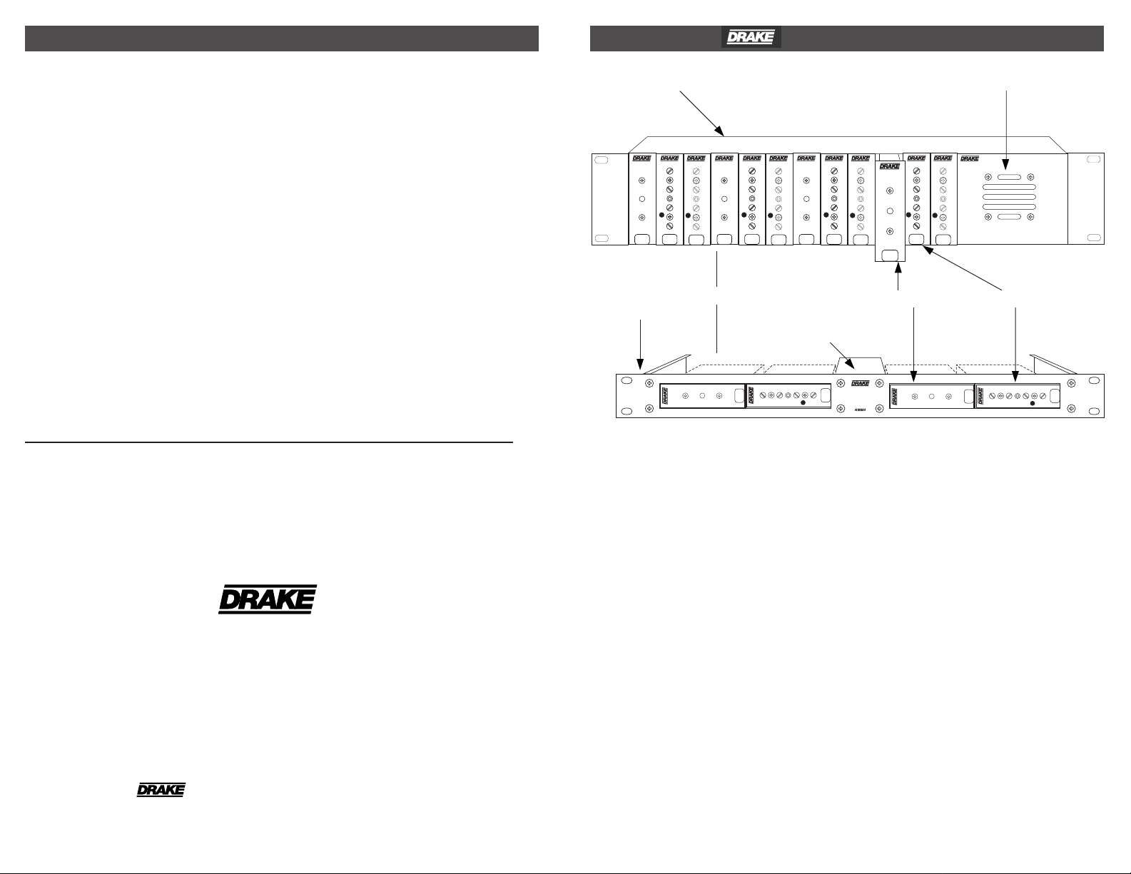
® TUM714 T CHANNEL UP-CONVERTER 1
12 POSITION RACK MOUNT POWER SUPPLY
PSM 121 POWER SUPPLY
DEMODULATOR
A/V
PWR
VIDEO
AUDIO
DMM806
RF
OR
TUM714
POWER
#
CH
DMM806
TUM714
VMM600
AUDIO
AUDIO
VIDEO
VIDEO
PWR
A/V
POWER
PWR
A/V
#
CH
RF
RF
DMM806
TUM714
POWER
#
CH
4 POSITION
VMM600
AUDIO
AUDIO
VIDEO
VIDEO
PWR
PWR
A/V
A/V
#
CH
RF
RACK MOUNT
POWER SUPPLY
TUM714
POWER
DMM806
AUDIO
#
CH
RF
A/V
PWR
VIDEO
DESCRIPTION
The R.L. Drake model TUM714 is a "T" channel
block up-converter packaged in a one unit wide
mini-rack package. This unit is compatible with
the Drake 12 position and 4 position rack
mounting frames for use in a 19" wide rack.
There are twelve one unit wide slots, in addition
to space for the power supply (in the 12 position
rack unit).
The up-converter accepts inputs in the "T"
channel range of 5 through 54 MHz and
up-converts an input signal to an output that is
168.25 MHz higher in frequency than the input.
Thus, "T" channels T7 through T14 are
converted to outputs at standard EIA CATV
channels 7 through 13 and channel 23.
DMM806
TUM714
POWER
RF
VMM600
AUDIO
AUDIO
VIDEO
VIDEO
PWR
PWR
A/V
A/V
#
#
CH
CH
RF
RF
#
CH
DMM806
VMM600
AUDIO
AUDIO
VIDEO
VIDEO
PWR
PWR
A/V
A/V
#
CH
RF
TUM714
POWER
TUM714
Typically, the TUM714 will be used in
conjunction with a demodulator to derive NTSC
video and audio from a "T" channel signal. The
maximum input signal level that can be
accepted by the TUM714 without significant
distortion is +30 dBmV. The TUM714 has
approximately unity gain. The unit may also be
used to translate digital QPSK, QAM, or USB
signals as well as analog NTSC signals.
RF
#
CH
® is a registered trademark of the R.L. Drake Company
© Copyright 2002 R.L. Drake Company P/N: 3852343A-6-2002 Printed in U.S.A.
Page 2
2
FRONT PANEL INDICATOR / REAR PANEL CONNECTIONS
INSTALLATION / SPECIFICATIONS 3
TUM714
F1
POWER
Figure 1
F1 - POWER Indicator
Lights when the unit is connected to the
required source of DC power via the rear panel
DC INPUT connector.
R1
R2
+5V
+12V
GND
R3
Figure 2
R1 - RF OUTPUT Connector
This is the RF output to a demodulator.
R2 - DC INPUT Connector
This 3-pin connector (Male) accepts the
appropriate mating DC power cable. Observe
proper orientation and wiring.
R3 - RF INPUT Connector
This is the RF input and accepts inputs from
5 to 54 MHz.
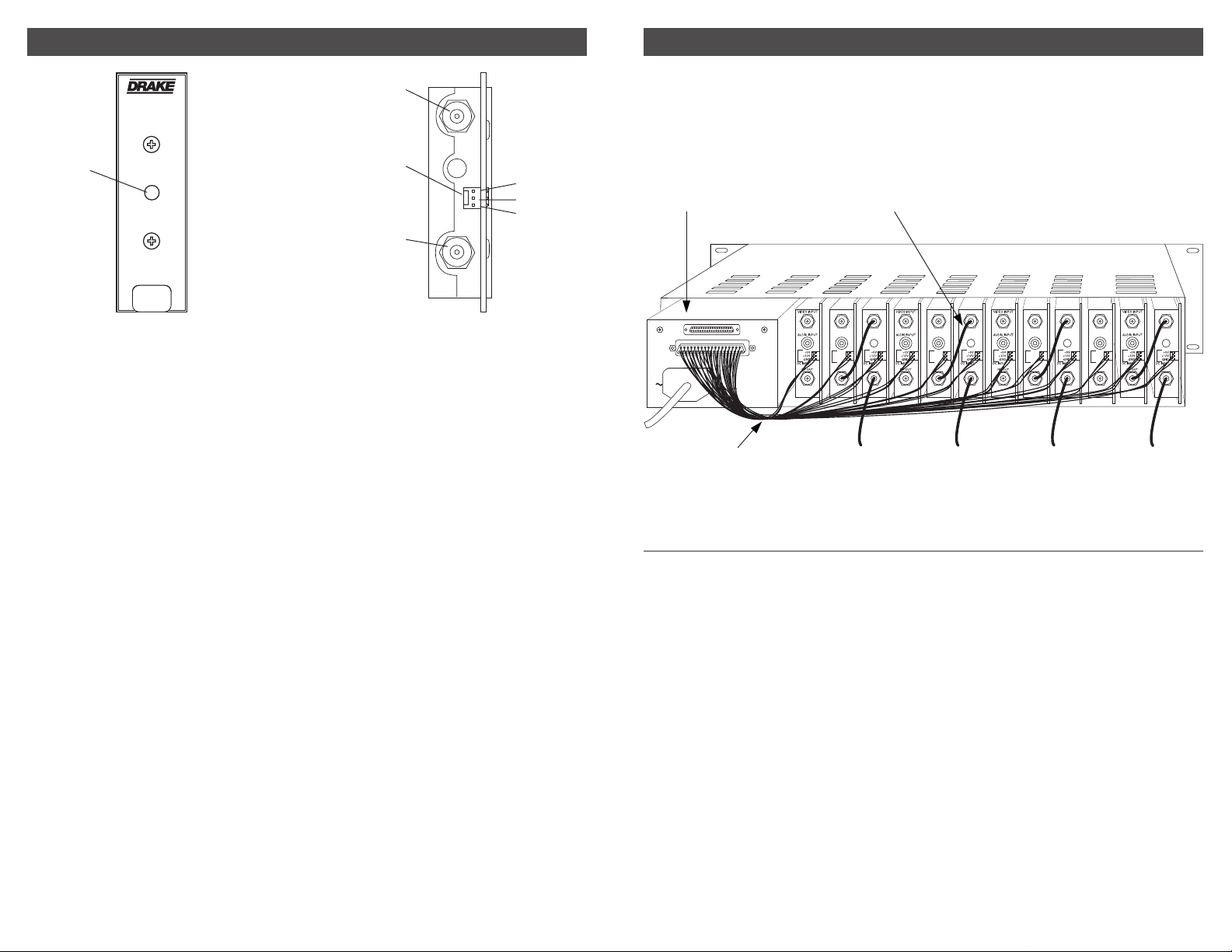
INSTALLATION
Mount the TUM714 in the 12 position rack
frame. Connect a power cable from the power
supply to the power connector on the TUM714.
Connect the "T" channel input as indicated in
Figure 3.
"RF OUT" OF TUM714 TO "RF IN" OF
POWER SUPPLY
20 37
119
+5 VDC
+12 VDC
(4.5A Max):
(3A Max):
Pins 1,4, 7,
Pins 2,3, 5,
12, 15, 18,
6, 8, 9, 11,
21, 24, 27,
13, 14, 16,
30, 33, 36.
17, 19.
100-240 V
50/60 Hz
75 WATTS
DEMODULATOR OR OTHER EQUIPMENT
VIDEO OUT RF OUT
AUDIO OUT
+5V
+12V
GND:
Pins 10, 20,
22, 23, 25,
26, 28, 29,
31, 32, 34,
35, 37.
GND
DC INPUT
RF IN RF IN
DC POWER CABLES
Connect the output from the TUM714 to the
demodulator input or to other desired
equipment.
VIDEO OUT
AUDIO OUT
+5V
+12V
GND
DC INPUT
RF IN
RF OUT
RF IN
VIDEO OUT
AUDIO OUT
+5V
+12V
GND
DC INPUT
RF IN
RF OUT
RF IN
FROM SUB-BAND
SIGNAL SOURCE TO
TUM714 "RF IN"
("T" CHANNEL INPUT)
VIDEO OUT
AUDIO OUT
+5V
+12V
GND
DC INPUT
RF IN
RF OUT
RF IN
SPECIFICATIONS
Power Requirement (from PSM121):
Figure 3
Input Frequency Range:
Input Impedance:
Output Frequency Range:
Output Impedance:
Gain:
Noise Figure:
L.O. Frequency:
Input Level:
Third Order Input Intercept Point:
Operating Temperature Range:
Size:
Weight
5 MHz to 54 MHz.
75 Ohms, return loss >14 dB.
173 MHz to 223 MHz.
75 Ohms, return loss >14 dB.
0 dB, ±2 dB.
<10 dB.
168.25 MHz, ±2 kHz.
+30 dBmV maximum for
-60 dB harmonics and intermods.
>+60 dBmV.
+12 V @ 75 mA.
+5 V @ 10 mA.
00 to +500 C, ambient.
1” W x 3.5” H x 8.75” D. (2.5 cm) W x (8.9 cm) H x
(22.2 cm) D.
10.2 oz. (0.3 Kg).
Specifications subject to change without notice or obligation.
 Loading...