

Page 1
8 WARRANTY AND SPECIFICATIONS
PS8
POWER SUPPLY
MPM860AG
GAIN
POWER/
ERROR
CATV
+100
BCTV
CATV
2 5
MPM860AG
GAIN
POWER/
ERROR
CATV
+100
BCTV
CATV
2 5
MPM860AG
GAIN
POWER/
ERROR
CATV
+100
BCTV
CATV
2 5
MPM860AG
GAIN
POWER/
ERROR
CATV
+100
BCTV
CATV
2 5
MPM860AG
GAIN
POWER/
ERROR
CATV
+100
BCTV
CATV
2 5
MPM860AG
GAIN
POWER/
ERROR
CATV
+100
BCTV
CATV
2 5
MPM860AG
GAIN
POWER/
ERROR
CATV
+100
BCTV
CATV
2 5
MPM860AG
GAIN
POWER/
ERROR
CATV
+100
BCTV
CATV
2 5
MPM860AG
GAIN
POWER/
ERROR
CATV
+100
BCTV
CATV
2 5
MPM860AG
GAIN
POWER/
ERROR
CATV
+100
BCTV
CATV
2 5
MPM860AG
GAIN
POWER/
ERROR
CATV
+100
BCTV
CATV
2 5
MPM860AG
GAI
POWER/
ERROR
CATV
+100
2
DRMM4
DRAKE
DRAKE
DRAKE
DRAKE
MPM860AG
GAIN
POWER/
ERROR
CATV
+100
BCTV
CATV
2 5
MPM860AG
GAIN
POWER/
ERROR
CATV
+100
BCTV
CATV
2 5
MPM860AG
GAIN
POWER/
ERROR
CATV
+100
BCTV
CATV
2 5
MPM860AG
GAIN
POWER/
ERROR
CATV
+100
BCTV
CATV
2 5
® MPM860AG Mini Processor Module 1
THREE YEAR LIMITED WARRANTY
R.L. DRAKE COMPANY warrants to the original purchaser this product shall be free from defects in material or workmanship for three (3)
years from the date of original purchase.
During the warranty period the R.L. DRAKE COMPANY or an authorized Drake service facility will provide, free of charge, both parts and
labor necessary to correct defects in material and workmanship. At its option, R.L. DRAKE COMPANY may replace a defective unit.
To obtain such warranty service, the original purchaser must:
(1) Retain invoice or original proof of purchase to establish the start of the warranty period.
(2) Notify the R.L. DRAKE COMPANY or the nearest authorized service facility, as soon as possible after discovery of a possible defect,
of:
(a) the model and serial number,
(b) the identity of the seller and the approximate date of purchase; and
(c) A detailed description of the problem, including details on the electrical connection to associated equipment and the list of such
equipment.
(3) Deliver the product to the R.L. DRAKE COMPANY or the nearest authorized service facility, or ship the same in its original container
or equivalent, fully insured and shipping charges prepaid.
Correct maintenance, repair, and use are necessary to obtain proper performance from this product. Therefore carefully read the Instruction
Manual. This warranty does not apply to any defect that R.L. DRAKE COMPANY determines is due to:
(1) Improper maintenance or repair, including the installation of parts or accessories that do not conform to the quality and specifications
of the original parts.
(2) Misuse, abuse, neglect or improper installation.
(3) Accidental or intentional damage.
All implied warranties, if any, including warranties of merchantability and fitness for a particular purpose, terminate three (3) years from the
date of the original purchase.
The foregoing constitutes R.L. DRAKE COMPANY’S entire obligation with respect to this product, and the original purchaser shall have
no other remedy and no claim for incidental or consequential damages, losses or expenses. Some states do not allow limitations on how
long an implied warranty lasts or do not allow the exclusions or limitation of incidental or consequential damages, so the above limitation
and exclusion may not apply to you.
This warranty gives you specific legal rights and you may also have other rights which vary from state to state. This warranty shall be
construed under the laws of Ohio.
®
R.L. DRAKE COMPANY
230 INDUSTRIAL DRIVE
CUSTOMER SERVICE AND PARTS TELEPHONE:
WORLD WIDE WEB SITE: http://www.rldrake.com
© Copyright 2010 R.L. Drake Company P/N: 3852548 Rev A-08-2010
FRANKLIN, OHIO 45005 U.S.A.
+1 (937) 746-6990
TELEFAX:
+1 (937) 806-1576
® is a registered trademark of the R.L. Drake Company
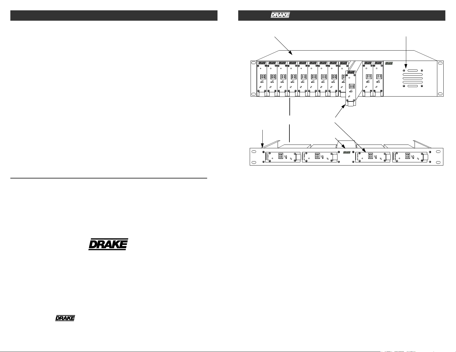
12 POSITION RACK MOUNT POWER SUPPLY
4 POSITION
OR
MPM860AG
RACK MOUNT
POWER SUPPLY
The MPM860AG mini processing module is a
member of the R.L. Drake 19" Mini-Rack
Series, a professional quality modular headend
system designed to optimize rack space. An
assortment of up to (12) modular units, such as
the fixed channel series of modulators, or agile
modulators, the MPM860AG, or compatible
The frequency agile MPM860AG allows front
panel pushwheel switch selection of standard
CATV channels 2 through 135, or VHF/UHF TV
channels 2 through 69. Aeronautical channels
are offset per FCC requirements. Internal
jumpers permit set up for HRC or IRC CATV
plans as well.
audio/video products can be racked alongside a
single power supply in the Drake model
RMM12, 12 position rack mount. The RMM4
rack mount accepts up to (4) modular units.
The heterodyne conversion system, in
conjunction with the use of a SAW filter,
ensures optimum vestigial selectivity for
adjacent channel headends.
The R.L. Drake MPM860AG is a miniature
analog double conversion heterodyne channel
processor designed specifically to accept a
channel 3 or channel 4 RF input from a typical
consumer CH3/4 NTSC modulator. The input
signal can be either double sideband as typical
for such a modulator, or vestigial sideband
modulated.
Note that the output of the MPM860AG is
related to the input signal's stability and level. A
nominal input level of +10 dBmV ± 3 dB is
desired at CH3 or CH4. The front panel gain
control on the MPM860AG can then be adjusted
to obtain a +45 dBmV output level. The
MPM860AG is linear and if the input level is
changed, the MPM output level will follow.
The MPM860AG contains SAW filtering to
insure that the output of the MPM860AG is a
vestigial sideband output for use in a 6 MHz
wide channel environment. Adjacent output
channels are allowed.
Page 2
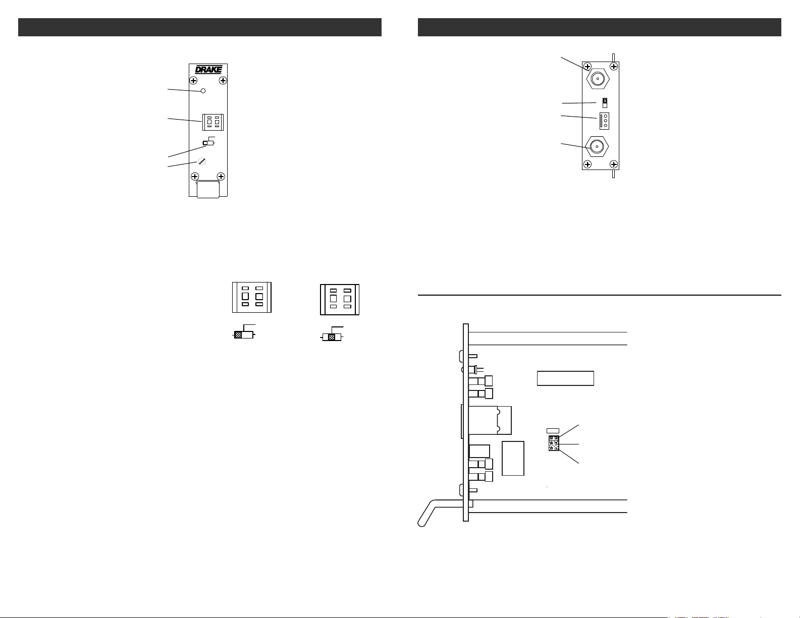
2 FRONT PANEL CONTROLS and INDICATORS
MPM860AG
GAIN
POWER/
ERROR
CATV
+100
BCTV
CATV
2 5
CATV
+100
BCTV
CATV
2 5
CATV
+100
BCTV
CATV
2 5
CHANNEL 3/4 IN
+12 V
GND
+5 V
RF OUT
CH 4
CH 3
DC INPUT
REAR PANEL CONNECTIONS / INTERNAL JUMPERS 3
MPM860AG
F1
F2
F3
F4
F1 - POWER/ERROR Indicator
Lights when the unit is connected to the
required source of DC power via the rear panel
DC INPUT connector. A flashing condition
indicates an invalid channel setting or other
conditions that would cause the unit to operate
on an invalid channel. The RF output is
switched off for flashing (ERROR) conditions.
F2 - Channel Select Switch
Sets the desired operating channel for standard
CATV channels 02 through 135 or Broadcast
TV channels 02 through 69. See also Item F3
which sets the type of channel (CATV or
Broadcast TV) and sets the leading “1” for
CATV channels 100 through 135.
F3 - Mode Switch
Sets the type of channel, CATV or Broadcast TV
(“BC TV”). The first position of the switch
Figure 1
(“+100”) sets a leading “1” for CATV channels
100 through 135. See also Item F4 for setting
the channel. Here are two examples:
Setting for CATV Setting for CATV
channel "125"- channel "25"-
F4 - Gain
This screwdriver adjustment permits adjustment of the MPM860AG gain over a minimum of
10 dB range. Adjust to set output level to +45
dBmV.
The MPM860AG is linear and if the input level
is changed, the MPM output level will follow.
R1
R2
R3
R4
R1 - CH 3 / CH 4 INPUT
+5 dBmV RF input.
R2 - Ch 3 / CH4 SELECT
Selects RF input between channel 3 and
channel 4.
MPM860AG
Figure 2
R3 - DC INPUT Connector
This 3-pin connector (Male) accepts the
appropriate mating DC power cable.
R4 - RF OUTPUT
This is the +45 dBmV RF output.
INTERNAL JUMPER SETTING: STD, HRC, IRC
STD Drawing is not to scale.
HRC No jumper installed gives STD setting.
IRC
Figure 3
Page 3

4 INSTALLATION
CAT V
+1 00
CATV
BC
TV
CATV
+10 0
CATV
BC
TV
CAT V
+1 00
CATV
BC
TV
CATV CHANNEL OUTPUT FREQUENCIES 5
CONNECTIONS AND CONTROLS
All connections to and from each processor are
made through the rear panel.
INSTALLATION NOTES
Level adjustment provides optimum
performance in multi-channel installations.
The output levels should be checked periodically
with a spectrum analyzer or appropriate meter to
insure output levels are properly set.
RACK MOUNTING
Adequate ventilation is very important in
rack mounting installations.Excessive heat will
shorten component life and performance.
The RMM12 or RMM4 cages should be spaced 1RU
apart wherever possible. Some air movement is
mandatory in enclosed rack cabinets.
POWER SUPPLY REQUIREMENT
Power for units mounted in the RMM12 rack
mounting cage is to be supplied by a Drake
model PSM121 power supply. Up to 12
processors may be powered.
The power supply in the four position rack
system can power up to four MPM860AGs.
FREQUENCY CHART
The chart on the following page shows the
standard CATV channel coverage. Where
an offset is indicated, this amount of
positive frequency offset is added to the
frequency indicated in the middle column.
As shown, this occurs only on channels
required to be offset by the FCC.
HRC or IRC frequencies can be set by
means of an internal jumper. See Figure 3.
No jumper will result in the STD channel
plan selection.
TABLE 1: CATV
Output Channel
Switch Setting
02
03
04
05
06
07
08
09
10
11
12
13
14
15
16
17
18
19
20
21
22
23
24
25
26
27
28
29
30
31
32
33
34
35
36
37
38
39
40
41
42
43
44
45
46
47
48
49
50
51
52
53
54
55
56
57
58
59
60
61
62
63
64
65
66
67
68
69
Visual Carrier
Frequency (MHz)
55.25
61.25
67.25
77.25
83.25
175.25
181.25
187.25
193.25
199.25
205.25
211.25
121.25
127.25
133.25
139.25
145.25
151.25
157.25
163.25
169.25
217.25
223.25
229.25
235.25
241.25
247.25
253.25
259.25
265.25
271.25
277.25
283.25
289.25
295.25
301.25
307.25
313.25
319.25
325.25
331.25
337.25
343.25
349.25
355.25
361.25
367.25
373.25
379.25
385.25
391.25
397.25
403.25
409.25
415.25
421.25
427.25
433.25
439.25
445.25
451.25
457.25
463.25
469.25
475.25
481.25
487.25
493.25
Frequency
Offset (kHz)
NONE
NONE
NONE
NONE
NONE
NONE
NONE
NONE
NONE
NONE
NONE
NONE
±12.5
±12.5
±12.5
NONE
NONE
NONE
NONE
NONE
NONE
NONE
+12.5
+12.5
+12.5
+12.5
+12.5
+12.5
+12.5
+12.5
+12.5
+12.5
+12.5
+12.5
+12.5
+12.5
+12.5
+12.5
+12.5
+12.5
+25
+12.5
+12.5
+12.5
+12.5
+12.5
+12.5
+12.5
+12.5
+12.5
+12.5
+12.5
NONE
NONE
NONE
NONE
NONE
NONE
NONE
NONE
NONE
NONE
NONE
NONE
NONE
NONE
NONE
NONE
Output Channel
Switch Setting
70
71
72
73
74
75
76
77
78
79
80
81
82
83
84
85
86
87
88
89
90
91
92
93
94
95
96
97
98
99
100
101
102
103
104
105
106
107
108
109
110
111
112
113
114
115
116
117
118
119
120
121
122
123
124
125
126
127
128
129
130
131
132
133
134
135
Visual Carrier
Frequency (MHz)
499.25
505.25
511.25
517.25
523.25
529.25
535.25
541.25
547.25
553.25
559.25
565.25
571.25
577.25
583.25
589.25
595.25
601.25
607.25
613.25
619.25
625.25
631.25
637.25
643.25
103.25
109.25
115.25
CATV +100
649.25
655.25
661.25
667.25
673.25
679.25
685.25
691.25
697.25
703.25
709.25
715.25
721.25
727.25
733.25
739.25
745.25
751.25
757.25
763.25
769.25
775.25
781.25
787.25
793.25
799.25
805.25
811.25
817.25
823.25
829.25
835.25
841.25
847.25
853.25
859.25
91.25
97.25
Frequency
Offset (kHz)
NONE
NONE
NONE
NONE
NONE
NONE
NONE
NONE
NONE
NONE
NONE
NONE
NONE
NONE
NONE
NONE
NONE
NONE
NONE
NONE
NONE
NONE
NONE
NONE
NONE
NONE
NONE
NONE
+25
+25
NONE
NONE
NONE
NONE
NONE
NONE
NONE
NONE
NONE
NONE
NONE
NONE
NONE
NONE
NONE
NONE
NONE
NONE
NONE
NONE
NONE
NONE
NONE
NONE
NONE
NONE
NONE
NONE
NONE
NONE
NONE
NONE
NONE
NONE
NONE
NONE
Page 4

6 BROADCAST TV CHANNEL OUTPUT FREQUENCIES
CAT V
+1 00
CATV
BC
TV
CAT V
+1 00
CATV
BC
TV
SPECIFICATIONS 7
TABLE 2: BC TV
VHF BROADCAST CHANNELS
Channel Number
2
3
4
5
6
7
8
9
10
11
12
13
Visual Carrier
Frequency (MHz)
55.25
61.25
67.25
77.25
83.25
175.25
181.25
187.25
193.25
199.25
205.25
211.25
UHF BROADCAST CHANNELS
Channel Number
14
15
16
17
18
19
20
21
22
23
24
25
26
27
28
29
30
31
32
33
34
35
36
37
38
39
40
41
42
43
44
45
46
47
48
49
50
51
52
53
54
55
56
57
58
59
60
61
62
63
64
65
66
67
68
69
Visual Carrier
Frequency (MHz)
471.25
477.25
483.24
489.25
495.25
501.25
507.25
513.25
519.25
525.25
531.25
537.25
543.25
549.25
555.25
561.25
567.25
573.25
579.25
585.25
591.25
597.25
603.25
609.25
615.25
621.25
627.25
633.25
639.25
645.25
651.25
657.25
663.25
669.25
675.25
681.25
687.25
693.25
699.25
705.25
711.25
717.25
723.25
729.25
735.25
741.25
747.25
753.25
759.25
765.25
771.25
777.25
783.25
789.25
795.25
801.25
Input Level:
Input Impedance:
Input frequency:
Frequency Range:
FCC Offsets:
Output level:
Output Impedance:
Frequency Stability:
Spurious:
Broadband Noise:
In Channel C/N:
In Channel
Frequency Response:
Output Level Note:
GENERAL
DC Power Input:
Operating Temperature:
Specifications subject to
change without notice or obligation.
Input
Output
Size:
Weight:
MPM860AG
-39 dBm / +10dBmV, ±3dB
75 ohm, 18dB return loss
Channel 3 (61.25 MHz Visual Carrier) or
Channel 4 (67.25 MHz Visual carrier)
Selectable via rear panel switch.
54 to 864 MHz.
Standard CATV channels 2 to 135, Normal operation.
HRC
, IRC Channels 1 - 135, Selected via internal jumper.
Broadcast channels 2 - 69, Selected via internal jumper.
Automatic, +12.5 kHz or +25 kHz channel dependant.
+45 dBmV
75 Ohm, 10 dB return loss.
±5 kHz
-60 dB @ +45 dBmV out.
-77dBc at greater than ± 12 MHz offset at +45 dBmV output,
4 MHz bandwidth.
57 dB, 4 MHz bandwidth.
Within 2 dB
The output level of the MPM860AG is intended to be set at or
very near +45dBmV. The front panel gain control adjusts the
input level into the conversion circuitry and not the final
output attenuation. For best noise and spurious performance
please adjust the output level to +45 dBmV with the actual
input that will be used with the device. If more than 1 or 2 dB
of variation is needed to properly equalize the system,
appropriate pads should be placed at the output of the
MPM860AG.
+5 V ±5% at 400 mA
+12 V ±5% at 200 mA
00 C to +500 C ambient.
1” W x 3.5” H x 7.5” D
12 oz.
 Loading...