

Drake digital DRMM12 DATASHEET
DRMM12 Rack Mount 1
The DRMM12 Rack Mount supports a single Drake Power
Supply and up to (8) modular Drake digital headend units to
configure a professional quality, modular, headend system,
which optimizes rack space. The DRMM12 mounts in a
standard 19" wide equipment rack and requires 3 1/2" of
vertical rack space. After installation of the PS8 Power Supply,
there are 12 single width slots available. Up to 8 separate
modules in combinations of 1, 2, or 3 units wide can be
installed into the rack. The PS8 will power up to 8 modules.
Identify the following items shipped with this kit of rack mount
assembly and cable assembly:
(1) DRMM12 Rack Mount chassis.
(1) Wire, ground bonding chassis to power supply
(P/N: 2700017).
(2) End Caps, Gray (P/N: 4801560).
Installation:
Adequate ventilation is very important in multi-channel
installations. Rack units should be spaced apart by at least
1 3/4" wherever possible, and some air movement is advisable in enclosed rack cabinets. Excessive heat will shorten
the life of components and individual module(s). Power
supply performance will also be degraded without proper
cooling.
If desired, the supplied gray end caps can be installed over
the mounting ears of the DRMM12 and secured by the rack
support screws.
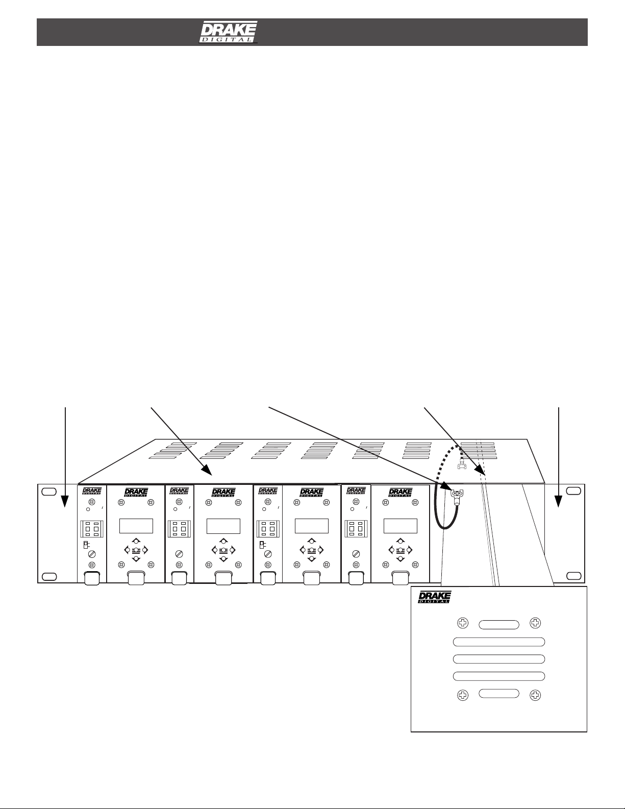
Locate the Power Supply (sold separately). Prior to sliding the
power supply into the right-hand side top and bottom slide
rails of the DRMM12, loosen the #6-32 screw located on the
top surface of the power supply. Position the free end of the
ground wire lug (other end of wire fastened to DRMM12) under
the #6-32 screw, and tighten the screw to secure the ground
wire. Slide the power supply into the DRMM12.
If necessary, use the following steps to remove the Drake
Power Supply from the rack:
1) Remove the module immediately adjacent to the Drake
Power Supply. Be aware that the module power cable will
become disconnected from the rear when the module is
removed.
2) Now grasp the edge of the Drake Power Supply front panel
and remove the unit from rack.
3) Reconnect the module power cable then replace the
adjacent module as required.
GRAY END CAP
(DECORATIVE)
P/N: 4801560)
DUC860
POWER
ERROR
2 5
CATV+100
CATV
GAIN
SECURE LUG (GROUND
BONDING WIRE) UNDER
DRMM12
TMQAM
QAM
MODULATOR
BIT RATE
19.327 M
ENTER
DUC550
7 5
POWER
ERROR
GAIN
#6-32 SCREW HEAD.
TMQAM
QAM
MODULATOR
BIT RATE
19.327 M
ENTER
DUC860
2 5
POWER
ERROR
CATV+100
CATV
GAIN
TMQAM
QAM
MODULATOR
BIT RATE
19.327 M
ENTER
FIGURE 1 - Front View of Rack Mount System with
Power Supply
SLIDE RAIL (INTERNAL
TO RACK CHASSIS, TOP
AND BOTTOM).
DUC550
7 5
POWER
ERROR
GAIN
TMQAM
QAM
MODULATOR
BIT RATE
19.327 M
ENTER
PS8
GRAY END CAP
(DECORATIVE)
P/N: 4801560)
POWER SUPPLY
2 DRMM12 Rack Mount, continued
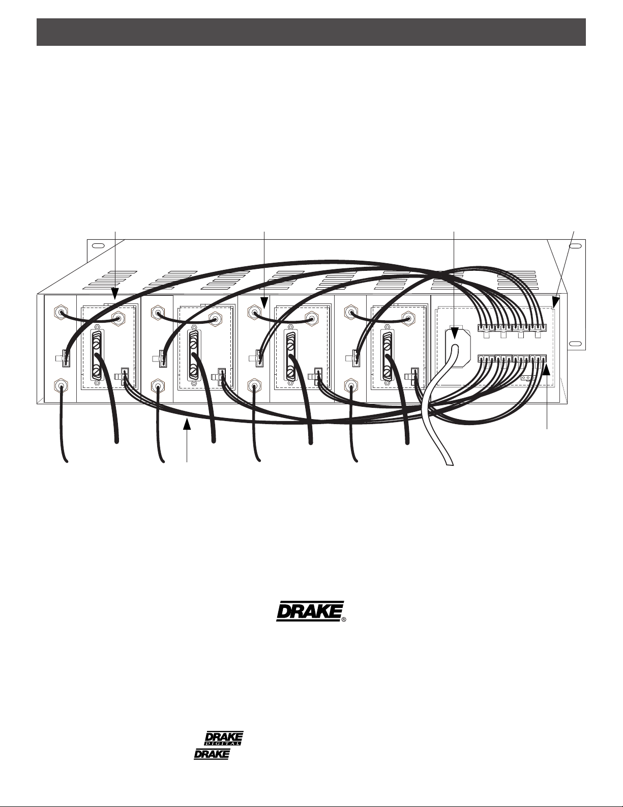
First, install the Drake PS8 Power Supply into the DRMM12.
Next, slide individual modules (maximum of 8 units) into the
desired rack locations. Connect the DC power cable,
supplied with each module, between each module and the
PS8 Power Supply.
QAM MODULATOR
IF IN
POWER
RF OUT
SPI LVDS INPUT
44 MHz
IF OUTPUT
POWER
IF IN
POWER
RF OUT
DIGITAL UPCONVERTER POWER SUPPLY
IF IN
44 MHz
IF OUTPUT
POWER
POWER
SPI LVDS INPUT
RF OUT
SPI LVDS INPUT
Avoid stretching the cables or routing them where damage to
the cable is likely. After the desired modules are installed into
the DRMM12 and the DRMM12 is secured in the rack,
connect the AC power cord of the power supply to a source of
AC pow er.
AC POWER CORD
IF IN
SPI LVDS INPUT
44 MHz
IF OUTPUT
POWER
90-260 VAC
DC OUTPUTS X 8
44 MHz
IF OUTPUT
POWER
POWER
RF OUT
12V GND 5V
DC POWER CABLE
FIGURE 2 - Rear View of System with 4 QAM Modulators and 4 Digital Upconverters.
R.L. DRAKE COMPANY
230 INDUSTRIAL DRIVE
FRANKLIN, OHIO 45005 U.S.A.
CUSTOMER SERVICE AND PARTS TELEPHONE: +1 (937) 746-6990
TELEFAX: +1 (937) 743-4576
WORLD WIDE WEB SITE: http://www.rldrake.com
MOLEX CONNECTOR
(TYPICAL)
TM is a trademark of the R.L. Drake Company
is a registered trademark of the R.L. Drake Company
© Copyright 2001 R.L. Drake Co. P/N: 3852375B-9-2001 Printed in the U.S.A.
 Loading...