

Page 1

4
THREE YEAR LIMITED WARRANTYTHREE YEAR LIMITED WARRANTY
THREE YEAR LIMITED WARRANTY
THREE YEAR LIMITED WARRANTYTHREE YEAR LIMITED WARRANTY
R.L. DRAKE COMPANY warrants to the original purchaser this product shall be free from defects in material or workmanship for three
(3) years from the date of original purchase.
During the warranty period the R.L. DRAKE COMPANY or an authorized Drake service facility will provide, free of charge, both parts
and labor necessary to correct defects in material and workmanship. At its option, R.L. DRAKE COMPANY may replace a defective
unit.
WARRANTY AND SPECIFICATIONS
To obtain such warranty service, the original purchaser must:
(1) Retain invoice or original proof of purchase to establish the start of the warranty period.
(2)(2)
(2) Notify the R.L. DRAKE COMPANY or the nearest authorized service facility, as soon as possible after discovery of a possible
(2)(2)
defect, of:
(a) the model and serial number,
(b) the identity of the seller and the approximate date of purchase; and
(c) A detailed description of the problem, including details on the electrical connection to associated equipment and the list of such
equipment.
(3)(3)
(3) Deliver the product to the R.L. DRAKE COMPANY or the nearest authorized service facility, or ship the same in its original
(3)(3)
container or equivalent, fully insured and shipping charges prepaid.
Correct maintenance, repair, and use are necessary to obtain proper performance from this product. Therefore carefully read the
Instruction Manual. This warranty does not apply to any defect that R.L. DRAKE COMPANY determines is due to:
(1)(1)
(1) Improper maintenance or repair, including the installation of parts or accessories that do not conform to the quality and
(1)(1)
specifications of the original parts.
(2)(2)
(2) Misuse, abuse, neglect or improper installation.
(2)(2)
(3)(3)
(3) Accidental or intentional damage.
(3)(3)
All implied warranties, if any, including warranties of merchantability and fitness for a particular purpose, terminate three (3) years
from the date of the original purchase.
The foregoing constitutes R.L. DRAKE COMPANY’S entire obligation with respect to this product, and the original purchaser shall
have no other remedy and no claim for incidental or consequential damages, losses or expenses. Some states do not allow limitations
on how long an implied warranty lasts or do not allow the exclusions or limitation of incidental or consequential damages, so the above
limitation and exclusion may not apply to you.
This warranty gives you specific legal rights and you may also have other rights which vary from state to state. This warranty shall
be construed under the laws of Ohio.
® DMM 806 VIDEO DEMODULATOR SYSTEM 1
RMM12 RACK MOUNT
VMM 600
VMM 600
VMM 600
AUDIO
AUDIO
VIDEO
PWR
A/V
#
CH
RF
RMM4 RACK
MOUNT
AUDIO
VIDEO
VIDEO
PWR
PWR
A/V
A/V
#
#
CH
CH
RF
RF
OR
VMM 600
#
CH
VMM 600
AUDIO
VIDEO
PWR
A/V
#
CH
RF
VMM 600
VMM 600
AUDIO
VIDEO
PWR
A/V
#
CH
RF
VMM 600
AUDIO
AUDIO
VIDEO
PWR
A/V
RF
AUDIO
VIDEO
VIDEO
PWR
PWR
A/V
A/V
#
#
CH
#
CH
CH
RF
RF
DRAKE MINI-RACK
SINGLE CHANNEL MODULATOR
POWER SUPPLY
VMM 600
CHCHCH
VMM 600
VMM 600
AUDIO
AUDIO
VIDEO
PWR
A/V
RF
AUDIO
VIDEO
VIDEO
PWR
PWR
A/V
A/V
#
CH
#
RF
CH
OFF AIR
RF
CATV
DRAKE MINI-RACK
POWER SUPPLY
DMM 806
PWR
CH
0
4
CATV
+
100
AUDIO
DMM 806
DEMODULATOR
DMM 806
PSM 120 POWER SUPPLY
POWER 1
POWER 2
CH
PWR
0
4
100
+
CATV
AUDIO
OFF AIR
CATV
SPECIFICATIONS
RF
Input Frequency:
Input Level:
Noise Figure:
Image Rejection:
Input Impedance:
VIDEO
Output Level:
Output Impedance:
Differential Gain:
Differential Phase:
L/C Delay:
54 - 806 MHz,
Off air channels
2 - 69,
CATV channels
2 - 125.
-10 to +35 dBmV.
VHF: 8 dB.
UHF: 10 dB.
VHF: 65 dB.
UHF: 50 dB.
75 Ohms.
1.0 Vp-p, NTSC
standard negative
sync.
75 Ohms.
Less than 5%.
Less than 5 degrees.
±50 nSec maximum.
AUDIO
Output Level:
Output Impedance:
GENERAL
DC Power Input:
Operating
Temperature:
Dimensions:
Weight:
300 mV rms nominal,
adjustable with front
panel control ±10 dB.
Less than 500 Ohms,
unbalanced.
+12 VDC @ 120 mA,
+5 VDC @ 100 mA.
00 C to +500 C.
1” W x 3.5” H x 7.5” D.
12 oz.
The R.L. Drake DMM 806 is a professional
quality agile television channel demodulator
that provides an audio and video output from
any VHF, UHF, or CATV channel
(54 - 806 MHz). The modular design of the
DMM 806 permits convenient pairing with a
Drake Mini-rack Video Modulator to perform
off-air or CATV channel processing.
As previously described, channel selection
switches and audio output level control are
located on the front panel. The RF Input is
through an “F” type connector located on the
rear panel. The rear panel Video Output is
also an “F” type connector. The Audio Output
is through a rear panel RCA type phono
connector. The unit is powered by a
compatible Drake Mini-rack power supply
The desired off-air VHF or UHF television
module.
channel from 2 through 69 or CATV channel
from 2 through 125 is selected by a front
panel pushwheel switch and associated slide
switch. The DMM 806 provides a standard
negative sync video output at a nominal level
of 1 Vp-p, and an audio output signal that is
level adjustable from approximately 0.5 to
1.5 Vp-p with a front panel control.
® is a registered trademark of the R.L. Drake Company
© Copyright 2001 R.L. Drake Company P/N: 3852324E-9-2001 Printed in U.S.A.
Page 2
2
FRONT PANEL DESCRIPTION REAR PANEL DESCRIPTION
INSTALLATION 3
F1
DMM 806
PWR
F2
F3
F4
OFF AIR
CATV
CH
0
4
CATV
+
100
AUDIO
Figure 1 Figure 2
F1 - POWER Indicator
Lights when the unit is connected to the
required source of DC power via the rear
panel DC INPUT connector.
F2- Channel Number Switch
Sets the received channel number for off-air
TV channels 02 through 69 or for CATV
channels 02 through 125. See also Item F3
which sets the type of channel (Off-Air or
CATV) and sets the leading “1” for CATV
channels 100 through 125.
F3 - Mode Switch
Sets the type of channel, Off-Air or CATV.
The third position sets a leading “1” for
CATV channels from 100 through 125. See
also Item F2 for setting the channel number.
For example: For example:
Setting for CATV Setting for CATV
channel "25"- channel "125"-
R1
R2
R3
VIDEO OUT
AUDIO OUT
+5V
+12V
GND
DC INPUT
RF IN
R4
R1 - VIDEO OUTPUT Connector
This is the 75 Ohm baseband video output at
a fixed, nominal 1.0 Vp-p level.
R2 - AUDIO OUTPUT Connector
This is the unbalanced, audio output which is
adjustable with the front panel AUDIO control
over a range of approximately ± 10 dB from
the nominal output level of 300 mV rms.
NOTE: An internal jumper defeats the audio
de-emphasis for stereo capability, if required.
R3 - DC INPUT Connector
This 3-pin connector (Male) accepts the
appropriate mating DC power cable.
Observe proper orientation and wiring.
R4 - RF INPUT Connector
This is the 75 Ohm input to the demodulator
circuits from an off-air television receiving
antenna or from a CATV cable input.
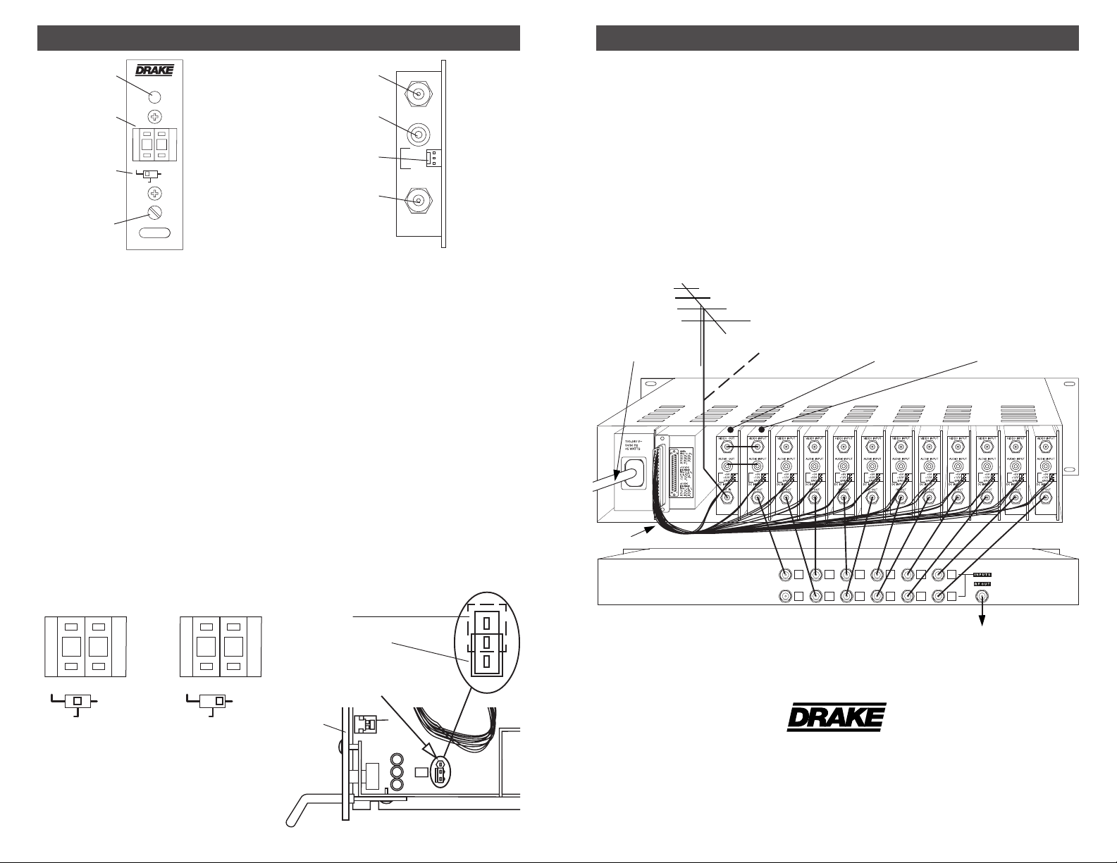
CONNECTIONS and CONTROLS
All connections to and from the DMM 806 are
made through the rear panel. Figure 3
illustrates the use of the DMM 806 as an offair channel processor. For this purpose, the
feed from a television antenna is connected
via a 75 Ohm coaxial cable to the RF IN
connector of the DMM 806. The front panel
switches are set for “OFF-AIR” and the
received TV channel number is set for 02
through 69 as required. The VIDEO OUT
and AUDIO OUT signals are connected to
the VIDEO IN and AUDIO IN connectors
respectively of an adjacently located Video
Modulator, such as a Drake Mini-rack Video
Modulator, operating on the desired cable TV
TV ANTENNA
AC POWER
CORD
DC POWER CABLE
OR
CATV FEED
channel. Alternatively, cable TV channels
can be processed by connecting the 75 Ohm
coaxial cable of a CATV feed to the DMM 806
RF IN connector and setting the front panel
switches for “CATV” or “CATV +100” and the
received cable channel number 02 through
125 as required. Additional channels can be
processed by adding combinations of
DMM 806 units with Drake Mini-rack Video
Modulator units.
RACK MOUNTING
Adequate ventilation is very important in
multi-channel installations. Units should be
spaced apart by at least one panel height
wherever possible, and some air movement
is advisable in enclosed rack cabinets.
Excessive heat will shorten component life
and system performance will be degraded
without proper cooling.
DRAKE MINI-RACK
DMM 806
VIDEO MODULATOR
2
OFF AIR
CATV
CH
5
CATV
+
100
2
OFF AIR
CATV
5
CATV
+
CH
100
F4 - AUDIO Output Level Control
This screwdriver adjustment permits setting
the audio output level over a range of
approximately 0.5 to 1.5 Vp-p.
Audio - Flat
Audio De-emphasis
(factory setting)
INTERNAL
JUMPER
Front
Panel
RF COMBINER
SYSTEM OUT
Figure 3
Illustration of Channel Processing using DMM 806 and a Drake Mini-rack Video Modulator.
®
R.L. DRAKE COMPANY
230 INDUSTRIAL DRIVE
FRANKLIN, OHIO 45005 U.S.A.
CUSTOMER SERVICE AND PARTS TELEPHONE:
WORLD WIDE WEB SITE: http://www.rldrake.com
+1 (937) 746-6990
TELEFAX:
+1 (937) 743-4576
 Loading...