

Page 1
1 DD860 DIGITAL DEMODULATOR
RF INPUT
POWER
SPI LVDS OUTPUT
13
1
25
14
+12 V GND +5 V
ASI TRANSPORT
STREAM OUTPUT
RF INPUT
POWER
SPI LVDS OUTPUT
13
1
25
14
+12 V GND +5 V
ASI TRANSPORT
STREAM OUTPUT
TM
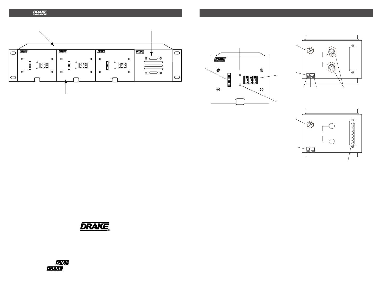
CONTROLS, INDICATORS AND CONNECTIONS 2
12 POSITION RACK MOUNT POWER SUPPLY
DD806
DIGITAL DEMODULATOR
LOCK
CHANNEL
SNR
40 dB
15 dB
0 4
ERROR
DD806
1
DIGITAL DEMODULATOR
LOCK
CHANNEL
SNR
40 dB
15 dB
0 4
ERROR
DD806
1
DIGITAL DEMODULATOR
LOCK
CHANNEL
SNR
40 dB
15 dB
0 4
ERROR
PS8
1
DD860 SATELLITE DEMODULATOR
The R.L. Drake model DD860 Digital
Demodulator is a professional quality modular
digital headend component designed to provide
A low phase noise tuner design provides
reliable operation with dense signal constella-
tions such as 256 QAM or 16 VSB.
optimum performance for VSB or QAM
demodulation. The DD860 receives an 8 VSB,
16 VSB, 64 QAM, or 256 QAM signal from a
An NTSC co-channel rejection filter for VSB
modes is incorporated.
terrestrial broadcast or CATV feed in the 54 to
858 MHz range, and demodulates the signal
providing an MPEG-2 digital transport stream
A wide range equalizer eliminates multipath
effects.
output.
QAM modes incorporate auto selection of ITU
The DD860 normally provides two 75 Ohm,
serial ASI outputs. A parallel SPI output is
A (DVB) or ITU B (DigiCipher II)
FEC.
available on special order.
IRC and HRC channel plans are selectable by
Front panel signal to noise ratio and staus
moving an internal jumper.
indicators are provided.
The DD860 is designed to mount in the
DRMM12 rack mounting cage.
R.L. DRAKE COMPANY
230 INDUSTRIAL DRIVE
FRANKLIN, OHIO 45005 U.S.A.
TELEFAX: +1 (937) 743-4576
WORLD WIDE WEB SITE: http://www.rldrake.com
TM is a trademark of the R.L. Drak e Company
® is a registered trademark of the R.L. Drake Company
CUSTOMER SERVICE AND PARTS TELEPHONE: +1 (937) 746-6990
© Copyright 2003 R.L. Drake Company P/N: 3852380A-1-2003 Printed in the U.S.A.
POWER SUPPLY
FRONT PANEL CONTROLS AND
INDICATORS
F1
DIGITAL DEMODULATOR
F2
DD806
40 dB
15 dB
LOCK
ERROR
CHANNEL
0 4
1
SNR
Figure 1
F1 - LOCK
This indicator shows that the demodulator is
receiving a valid digital signal and has locked
to it.
F2 - LED Signal-to-Noise Ratio Meter
Indicates the signal-to-noise ratio of the
received signal. The range is between 15 dB
and 40 dB. Threshold levels are nominally
15 dB for 8VSB, 29 db for 16VSB, 23 db for
64 QAM, and 28dB for for 256QAM. These are
minimum levels required for lock. Normal
operating levels must exceed threshold by
several dB to ensure reliable operation.
F3 - CHANNEL Selector Switch
This switch is used to enter the two or three
digit channel number. The range of numbers is
also used to determine the mode of operation.
F4 - ERROR
This indicator shows that the FEC is not able to
correct all errors in the received signal. Check
for a low signal-to-noise ratio or improper
antenna aiming if errors occur.
REAR PANEL CONNECTIONS
R1
R2
F3
+12V GND +5
R3
Figure 2 (ASI)
F4
R1
R2
Figure 3 (SPI)
R1 - RF INPUT
This "F" type connector is the input for the
tuner. The DD860 will tune to all U.S.A. off air
broadcast frequencies or to standard EIA CATV
channels up to 858 MHz (channel 134).
R2 - DC Power Connector
This is the power input connector. Connect to a
Drake PS8 or equivalent power supply.
R3 - BNC Connectors (ASI output model)
These are the MPEG2 transport stream
outputs. The ASI (Asynchronous Serial
Interface) Output Impedance is 75 Ohms.
R4 - 25 Pin SPI LVDS OUTPUT Connector
(SPI output model)
This is the MPEG2 transport stream output.
The DVB Synchronous Parallel Interface levels
comply with low voltage differential signalling
specifications.
R4
Page 2
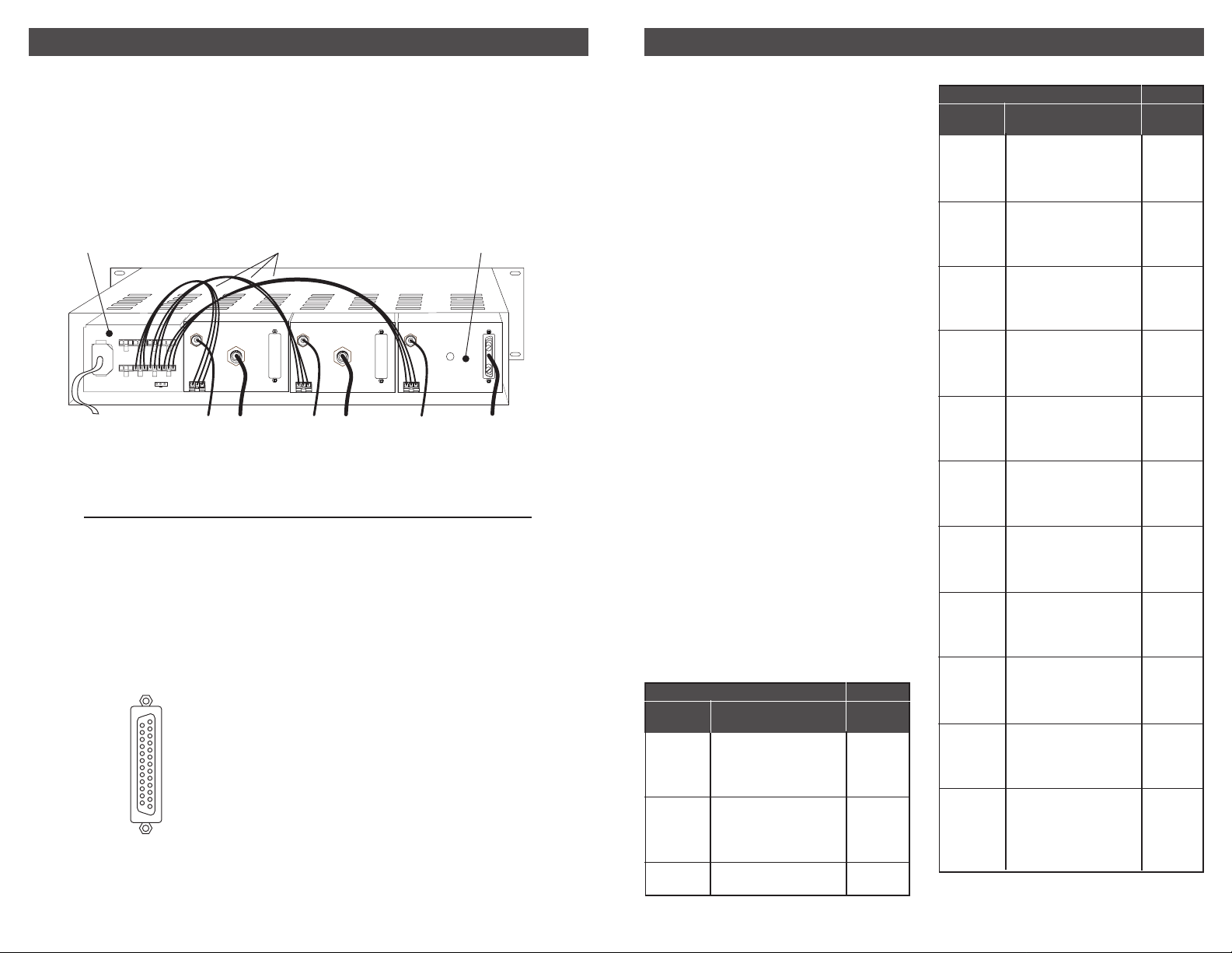
3 INSTALLATION
DD860 CHANNEL SELECTION / CHANNEL CHARTS 4
All connections to and from each module are
made through the rear panel. Refer to Figure 4
for correct cable and wiring connections.
RACK MOUNTING
Adequate ventilation is very important in
multichannel installations.
PS8 POWER SUPPLY
90-260 VAC
DC OUTPUTS X 8
AC POWER
CORD
FROM OFF-AIR
ANTENNA OR CATV
12V GND 5V
POWER SUPPLY CABLES
RF INPUT
POWER
+12 V GND +5 V
ASI TRANSPORT
STREAM OUTPUT
25
SPI LVDS OUTPUT 4
14
The DD860 is designed to mount into the
DRMM12 rack mounting enclosure.
The DD860 is four units wide. Power for the
DD860 should be supplied by the model PS8
power supply module which also mounts into
the DRMM12.
Pin Out DVB SPI Interface
14 Data Clk 15 GND
16 Data 7 17 Data 6 18 Data 5 19 Data 4 20 Data 3 21 Data 2 22 Data 1 23 Data 0 24 Data Valid 25 Start of Packet -
25
14
1 Data Clk +
2 GND
13
3 Data 7 +
4 Data 6 +
5 Data 5 +
6 Data 4 +
7 Data 3 +
8 Data 2 +
9 Data 1 +
1
10 Data 0 +
11 Data Valid +
12 Start of Packet +
13 GND
The DRMM12 frames should be spaced apart
vertically by at least 1 3/4" wherever possible.
Air movement is mandatory in enclosed rack
cabinets. Excessive heat will shorten
component life.
DD860
DEMODULATOR UNIT
RF INPUT
13
1
POWER
+12 V GND +5 V
ASI TRANSPORT
STREAM OUTPUT
TO
QAM ASI
INPUT
25
SPI LVDS OUTPUT 4
14
RF INPUT
13
POWER
1
+12 V GND +5 V
ASI TRANSPORT
STREAM OUTPUT
25
SPI LVDS OUTPUT 4
14
TO
QAM SPI
INPUT
Figure 4
The front panel channel selection switches are
used to select the mode of demodulation, the
desired band plan (CATV or Broadcast) and the
specific channel number. Four blocks of 133
channels each are allocated to CATV channels
and two blocks of 68 channels each are
allocated for off-air broadcast frequencies.
CATV channels in 64 QAM modulation are
selected using switch settings 002 through 134.
These switch settings correspond directly to the
EIA CATV channel numbers.
CATV channels in 256 QAM modulation are
selected using switch settings 202 through 334.
To determine the switch setting, add 200 to the
13
desired EIA CATV channel number.
CATV channels in 8 VSB modulation are
1
selected using switch settings 402 through 534.
To determine the switch setting, add 400 to the
desired EIA CATV channel number.
CATV channels in 16 VSB modulation are
selected using switch settings 602 through 734.
To determine the switch setting, add 600 to the
desired EIA CATV channel number.
Off-Air Broadcast channels in 8 VSB may be
tuned by selecting channels 802 through 869.
Add 800 to the broadcast channel number that
corresponds to the actual RF transmission
channel. Do not enter the virtual channel
number, used by some broadcasters.
NOTE: IRC and HRC CATV formats are
supported by setting of an internal jumper.
OFF-AIR
VHF BROADCAST CHANNELS 8VSB
Channel
Number
2
3
4
5
6
7
8
9
10
11
12
13
Center of Channel
Frequency (MHz)
57
63
69
79
85
177
183
189
195
201
207
213
DD860
Channel
802
803
804
805
806
807
808
809
810
811
812
813
UHF BROADCAST CHANNELS 8VSB
Channel
Number
14
15
16
17
18
19
20
21
22
23
24
25
26
27
28
29
30
31
32
33
34
35
36
37
38
39
40
41
42
43
44
45
46
47
48
49
50
51
52
53
54
55
56
57
58
59
60
61
62
63
64
65
66
67
68
69
Center of Channel
Frequency (MHz)
473
479
485
491
497
503
509
515
521
527
533
539
545
551
557
563
569
575
581
587
593
599
605
611
617
623
629
635
641
647
653
659
665
671
677
683
689
695
701
707
713
719
725
731
737
743
749
755
761
767
773
779
785
791
797
803
DD860
Channel
814
815
816
817
818
819
820
821
822
823
824
825
826
827
828
829
830
831
832
833
834
835
836
837
838
839
840
841
842
843
844
845
846
847
848
849
850
851
852
853
854
855
856
857
858
859
860
861
862
863
864
865
866
867
868
869
OFF-AIR
Page 3

5 CHANNEL CHARTS, contin ued
CHANNEL CHARTS, continued 6
B
A
N
D
L
O
W
M
I
D
H
I
G
H
S
U
P
E
R
H
Y
P
E
R
Channel
Number
EIA/NCTA
Numeric
Equivalent
2
3
4
5
6
95
96
97
98
99
14
15
16
17
18
19
20
21
22
7
8
9
10
11
12
13
23
24
25
26
27
28
29
30
31
32
33
34
35
36
37
38
39
40
41
42
43
44
45
46
Center of
Channel
Frequency
in MHz
57
63
69
79
85
93
99
105
111
117
123
129
135
141
147
153
159
165
171
177
183
189
195
201
207
213
219
225
231
237
243
249
255
261
267
273
279
285
291
297
303
309
315
321
327
333
339
345
351
357
CABLE TV CHANNELS
64 QAM 256 QAM 8 VSB 16 VSB
DD860
Channel
2
3
4
5
6
95
96
97
98
99
14
15
16
17
18
19
20
21
22
7
8
9
10
11
12
13
23
24
25
26
27
28
29
30
31
32
33
34
35
36
37
38
39
40
41
42
43
44
45
46
DD860
Channel
202
203
204
205
206
295
296
297
298
299
214
215
216
217
218
219
220
221
222
207
208
209
210
211
212
213
223
224
225
226
227
228
229
230
231
232
233
234
235
236
237
238
239
240
241
242
243
244
245
246
DD860
Channel
402
403
404
405
406
495
496
497
498
499
414
415
416
417
418
419
420
421
422
407
408
409
410
411
412
413
423
424
425
426
427
428
429
430
431
432
433
434
435
436
437
438
439
440
441
442
443
444
445
446
DD860
Channel
602
603
604
605
606
695
696
697
698
699
614
615
616
617
618
619
620
621
622
607
608
609
610
611
612
613
623
624
625
626
627
628
629
630
631
632
633
634
635
636
637
638
639
640
641
642
643
644
645
646
B
A
N
D
H
Y
P
E
R
Channel
Number
EIA/NCTA
Numeric
Equivalent
47
48
49
50
51
52
53
54
55
56
57
58
59
60
61
62
63
64
65
66
67
68
69
70
71
72
73
74
75
76
77
78
79
80
81
82
83
84
85
86
87
88
89
90
91
92
93
94
100
Center of
Channel
Frequency
in MHz
363
369
375
381
387
393
399
405
411
417
423
429
435
441
447
453
459
465
471
477
483
489
495
501
507
513
519
525
531
537
543
549
555
561
567
573
579
585
591
597
603
609
615
621
627
633
639
645
651
CABLE TV CHANNELS
64 QAM 256 QAM 8 VSB 16 VSB
DD860
Channel
47
48
49
50
51
52
53
54
55
56
57
58
59
60
61
62
63
64
65
66
67
68
69
70
71
72
73
74
75
76
77
78
79
80
81
82
83
84
85
86
87
88
89
90
91
92
93
94
100
DD860
Channel
247
248
249
250
251
252
253
254
255
256
257
258
259
260
261
262
263
264
265
266
267
268
269
270
271
272
273
274
275
276
277
278
279
280
281
282
283
284
285
286
287
288
289
290
291
292
293
294
300
DD860
Channel
447
448
449
450
451
452
453
454
455
456
457
458
459
460
461
462
463
464
465
466
467
468
469
470
471
472
473
474
475
476
477
478
479
480
481
482
483
484
485
486
487
488
489
490
491
492
493
494
500
DD860
Channel
647
648
649
650
651
652
653
654
655
656
657
658
659
660
661
662
663
664
665
666
667
668
669
670
671
672
673
674
675
676
677
678
679
680
681
682
683
684
685
686
687
688
689
690
691
692
693
694
700
Page 4

7 CHANNEL CHARTS, contin ued
CABLE TV CHANNELS
B
A
N
D
H
Y
P
E
R
Channel
Number
EIA/NCTA
Numeric
Equivalent
101
102
103
104
105
106
107
108
109
110
111
112
113
114
115
116
117
118
119
120
121
122
123
124
125
126
127
128
129
130
131
132
133
134
Center of
Channel
Frequency
in MHz
657
663
669
675
681
687
693
699
705
711
717
723
729
735
741
747
753
759
765
771
777
783
789
795
801
807
813
819
825
831
837
843
849
855
64 QAM 256 QAM 8 VSB 16 VSB
DD860
Channel
101
102
103
104
105
106
107
108
109
110
111
112
113
114
115
116
117
118
119
120
121
122
123
124
125
126
127
128
129
130
131
132
133
134
DD860
Channel
301
302
303
304
305
306
307
308
309
310
311
312
313
314
315
316
317
318
319
320
321
322
323
324
325
326
327
328
329
330
331
332
333
334
DD860
Channel
501
502
503
504
505
506
507
508
509
510
511
512
513
514
515
516
517
518
519
520
521
522
523
524
525
526
527
528
529
530
531
532
533
534
DD860
Channel
701
702
703
704
705
706
707
708
709
710
711
712
713
714
715
716
717
718
719
720
721
722
723
724
725
726
727
728
729
730
731
732
733
734
8
WARRANTY
THREE YEAR LIMITED WARRANTYTHREE YEAR LIMITED WARRANTY
THREE YEAR LIMITED WARRANTY
THREE YEAR LIMITED WARRANTYTHREE YEAR LIMITED WARRANTY
R.L. DRAKE COMPANY warrants to the original purchaser this product shall be free from defects in material or workmanship for three (3)
years from the date of original purchase.
During the warranty period the R.L. DRAKE COMPANY or an authorized Drake service facility will provide, free of charge, both parts and
labor necessary to correct defects in material and workmanship. At its option, R.L. DRAKE COMPANY may replace a defective unit.
To obtain such warranty service, the original purchaser must:
(1)(1)
(1) Retain invoice or original proof of purchase to establish the start of the warranty period.
(1)(1)
(2)(2)
(2) Notify the R.L. DRAKE COMPANY or the nearest authorized service facility, as soon as possible after discovery of a possible defect,
(2)(2)
of:
(a) the model and serial number,
(b) the identity of the seller and the approximate date of purchase; and
(c) A detailed description of the problem, including details on the electrical connection to associated equipment and the list of such
equipment.
(3)(3)
(3) Deliver the product to the R.L. DRAKE COMPANY or the nearest authorized service facility, or ship the same in its original container
(3)(3)
or equivalent, fully insured and shipping charges prepaid.
Correct maintenance, repair, and use are necessary to obtain proper performance from this product. Therefore carefully read the Instruction
Manual. This warranty does not apply to any defect that R.L. DRAKE COMPANY determines is due to:
(1)(1)
(1) Improper maintenance or repair, including the installation of parts or accessories that do not conform to the quality and specifications
(1)(1)
of the original parts.
(2)(2)
(2) Misuse, abuse, neglect or improper installation.
(2)(2)
(3)(3)
(3) Accidental or intentional damage.
(3)(3)
All implied warranties, if any, including warranties of merchantability and fitness for a particular purpose, terminate three (3) years from the
date of the original purchase.
The foregoing constitutes R.L. DRAKE COMPANY’S entire obligation with respect to this product, and the original purchaser shall have no
other remedy and no claim for incidental or consequential damages, losses or expenses. Some states do not allow limitations on how long
an implied warranty lasts or do not allow the exclusions or limitation of incidental or consequential damages, so the above limitation and
exclusion may not apply to you.
This warranty gives you specific legal rights and you may also have other rights which vary from state to state. This warranty shall be
construed under the laws of Ohio.
SPECIFICATI0NS
RF TUNER
Input Frequency:
Input Channel Bandwidth:
Input Impedance/Return Loss:
Optimum Input Level Range:
Maximum Input Power:
Input Noise Figure:
Input AGC Range:
DEMODULA TO R
Modulation T ypes Accepted:
Symbol Clock Frequency:
Symbol Rates:
Equalizer Span:
OUTPUTS
ASI Output Version - Serial Output:
SPI Output Version - Parallel Output:
GENERAL
DC Power Requirement:
Operating T emperature Range:
Mechanical Dimensions:
54 to 858 MHz, Broadcast or EIA CA TV Channels (Std., IRC , HRC).
6 MHz.
75 Ohms/R.L. of 6 dB minimum.
-15 dBmV to +15 dBmV.
< -16 dBm summed over entire input range.
12 dB, maximum.
-20 to +30 dBmV.
8VSB, 16VSB, 64QAM, and 256QAM.
8VSB; 10.762 MHz.
16VSB; 10.762 MHz.
64QAM; 5.057 Ms/sec.
256QAM; 5.3605 Ms/sec.
-6 to +40 µSec delays.
ASI according to DVB specifications via two 75 Ohm type BNC connectors .
SPI according to DVB specifications. L VDS le v els via one DB25 connector.
5 VDC@ 750 mA, 12 VDC @ 85 mA (Supplied by Drake PS8 power supply).
00 C to + 500 C Ambient temperature around case.
4.2" W x 3.5" H x 8.38" D, (10.7 cm W x 8.9 cm H x 21.3 cm D).
Weight:
1 lb. 9 oz. (.72 kg.).
 Loading...