

Drake digital DAR8642, DAR7542, DAR7533, DAR8618, DAR8633 QUICK GUIDE
®
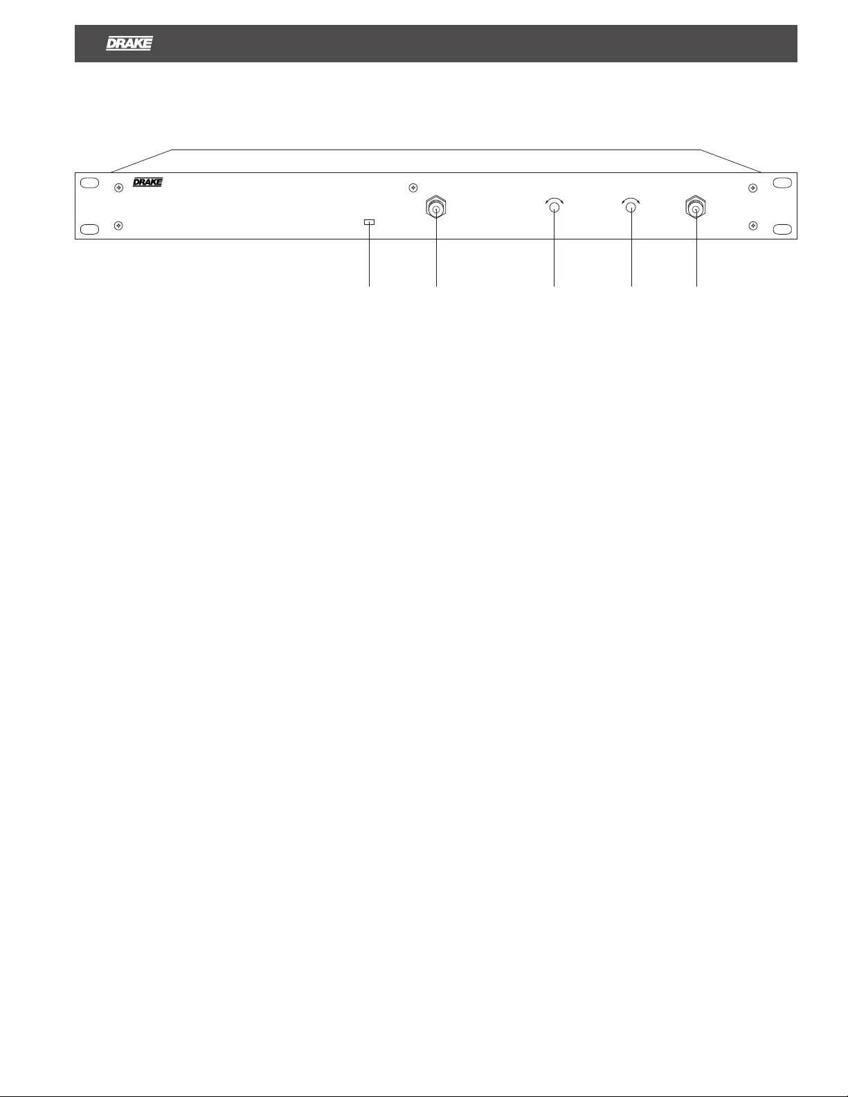
Rack Mount Distribution Amplifiers, with Power Doubled Hybrid Output 1
POWER
F1 F2 F3 F4 F5
DESCRIPTION
The R.L. DRAKE models DAR8642, DAR8633, DAR8618,
DAR7542, and DAR7533, are broadband distribution
amplifiers designed for indoor headend use in both
residential and commercial buildings where RF signal
distribution in the frequency range of 54 to 860 MHz is
required. Each model, except the DAR8618, incorporates a
push-pull hybrid input preamp and a power doubled hybrid
output amplifier to provide a very low distortion signal for
launch amp applications in the output of an SMATV or CATV
headend. The Gain and Slope controls both have a range of
10 dB minimum and operate between the preamp hybrid
and the output hybrid to maintain a low noise figure over a
wide range of gain and slope settings. Only the DAR8618
has a power doubled output hybrid with no input preamp and
no adjustable gain and slope controls. All models have a
provision for optional fixed input attenuators and equalizers.
Double-sided, plated through hole, glass epoxy, printed
circuit boards, and SMT are used for low losses and
maximum reliability.
INPUT MONITOR
-30 dB
GAIN SLOPE
MIN. MAX.
DAR DISTRIBUTION AMPLIFIER
MIN. FLAT
OUTPUT MONITOR
-30 dB
F1 - POWER LED
This indicator illuminates when power is supplied to the unit.
F2 - INPUT MONITOR
This connector may be used to monitor input to the DAR.
The levels will be 30 dB below the input levels at R3.
F3 - GAIN*
Adjusts the amplifier interstage attenuator.
F4 - SLOPE*
Adjusts the slope of the output signal.
F5 - OUTPUT MONITOR
This connector may be used to monitor the output of the
DAR. Levels will be 30 dB below those present at R2.
R2 must be terminated in 75 Ohms for an accurate reading.
*
Not present on models with gain below 20 dB.
All DAR models include a built-in diplexer filter. This allows
the return path energy that is present at the output por t of
the DAR to be separated from the DAR output and passed
to the return path output port.
Input and output test connectors are provided for convenient
monitoring of the signal path. The amplifier circuitr y is
designed for maximum stability, low distortion, low noise
figure, and is protected in a rugged aluminum housing.
- The unit operates from a nominal 115 VAC, 60 Hz input.
- Input equalizer and fixed attenuator options are available.

2 Rear Panel Connections
RETURN PATH
OUTPUT
RF OUTPUT
RF INPUT
FUSE
1/2 A , 250 V SLO - BLO
FUSE
R1 R2 R3 R4 R5
R1 - RETURN PATH OUTPUT
Any return path signals from 5 to 42 MHz that are present at
R2 will be passed to this port.
R2 - RF OUTPUT
This is the RF output for CATV distribution and is the
amplified output of channels that are input to port R3 from
54 MHz and higher. At this port, any return path channels
from 5 to 42 MHz will be passed at unity gain to port R1.
R3 - RF INPUT
This connector accepts the RF input from a headend
combiner output, 54 MHz and higher.
115 VAC , 60 Hz
40 WATTS
R4 - FUSE
If necessary, replace this fuse only with a fuse of the same
indicated rating.
R5 - AC LINE CORD
Connect this line cord to a 115 V / 60 Hz AC power source.
 Loading...