

Page 1
TM
1
Model 100-2366 Packet Processing/ASI TS Output Option Board (SCT860)
Installation 2
INTRODUCTION
The 1002366 board is used to process the
transport stream after satellite demodulation and before QAM modulation. It
enables the FIXED CLOCK mode of
operation (AUTO CLOCK mode is still
selectable), performs PCR correction, and
it also provides an ASI output of the
demodulated transport stream.
TRANSPORT STREAM PROCESSING
The transport stream processing feature
of the 1002366 board will add null packets
if the SCT860 is set to the FIXED CLOCK
mode and the demodulated transport
stream data rate is less than the rate set
as the fixed output rate. The 1002366 can
also drop extra null packets from the
transport stream when required to obtain
the desired output rate.
The standard SCT860 does not modify the
transport stream - Drake labels this mode
the ‘AUTO CLOCK’ mode as the output
rate is automatically determined by the
received input signal data rate. When the
SCT860, with the 1002366 installed, is set
to the AUTO CLOCK mode setting, it
operates as if the board were not installed;
the null packets will not be processed and
neither dropping or adding will occur.
The 1002366 option board must be
installed into the SCT860, and the
SCT860 firmware must be updated, in
order to activate the FIXED CLOCK mode.
The null packet processing functions are
enabled in the FIXED CLOCK mode. The
AUTO CLOCK mode can still be selected
in the menu.
When the SCT860, with the1002366
board, is set to the FIXED CLOCK
setting, all null packets will be dropped
from the demodulated transport stream.
The rate is then built back up, by adding
null packets, to the fixed output QAM
symbol (baud) rate that is set via the front
panel. Dropping null packets is required in
some cases in order to bring the rate
down to or below the desired rate when
the satellite uplink may add extra null
packets.
PCR CORRECTION
The SCT860 performs PCR correction on
the processed transport stream before
QAM modulation when the SCT860 is
used with the 1002366 option and is set
up in the FIXED CLOCK mode. No PCR
adjustments are made when the unit is set
to the AUTO CLOCK mode.
ASI OUTPUT
The 1002366 option board also adds an
ASI transport stream output connector to
the SCT860. A chassis mount type BNC
connector with coaxial cable is provided
for those who have a requirement for this
feature. The ASI output will be the demodulated satellite signal transport stream
output, without processing. It is provided in
DVB ASI format.
This output may be used to feed the
satellite signal transport stream to a
multiplexer where part of the stream may
be needed for remultiplexing with another
stream for another output channel.
If ASI output is not a requirement, place
the connector assembly in a storage
location for possible future use.
If the ASI output feature is desired, plug in
the supplied BNC connector cable to the
SCT860 PC board as indicated in Figure 3
and mount the BNC connector in the rear
panel mounting hole. If your SCT860
does not have this hole, it must be added.
The unit can be returned to the Drake
Service Department, if necessar y, for this
installation.
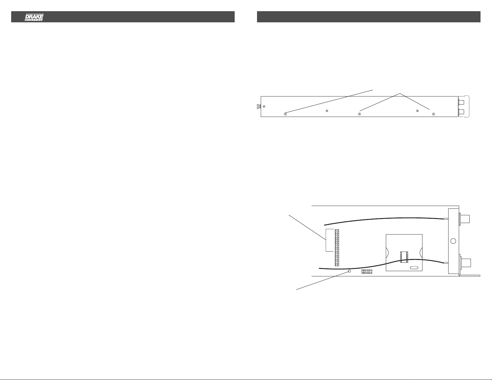
INSTALLATION IN THE SCT860
Looking at the SCT860 from the front panel,
observe the right side of the unit.
Remove the three top screws as shown,
three side screws, and three bottom screws
holding the right side of the case.
3 TOP SCREWS
Remove the right side and then lay the
transcoder on a flat surface laying on its left
side.
Locate the 36 pin interface connector and
remove the 11 jumpers that are in place.
Keep these jumpers for future use in case
the 100-2366 board is ever removed.
REMOVE 11 JUMPERS FROM THE 36 PIN CONNECT OR
LOCATION A
Page 2
3
Installation, continued
Operation 4
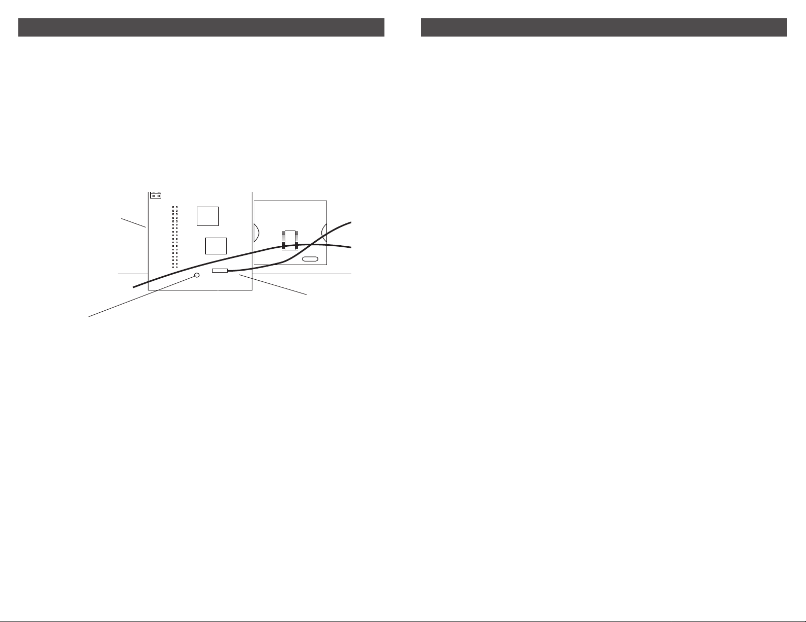
Remove the original screw at location A.
Screw the standoff spacer, that is included
with the option board, into the hole at
location A. Carefully remove the 100-2369
board from its static protection package.
Position the board as indicated and plug it
into the 36 pin connector.
PLUG INTERF AC E
HEADER INTO 36 PIN
CONNECTOR
TIGHTEN SCREW
INTO SPACER
FIGURE 3
Reinstall the screw to fasten the Option
Board to the spacer. Replace the right
side cover and screws.
OPERATION
Follow the instructions in the SCT860
instruction manual. Now that the 100-2366
board is installed, the FIXED clock option
may be selected and the output BD RATE
(baud rate which is the symbol rate) may
be set. The original AUTO clock mode is
still selectable, if desired.
PLUG IN SUPPLIED
BNC CONNECTOR
CABLE HERE
UPDATE FIRMWARE
In order for the fixed clock option, provided
by the 1002366 board, to operate in the
SCT860, it is necessary to change the
firmware in the SCT860 to the fixed clock
version. Unless your SCT860 was ordered
from the factory with the 1002366 board
installed, you will need to download the
correct firmware to the SCT860. This will
be accomplished by means of the RS232
PC interface on the PS100 power supply.
The fixed clock firmware is provided on
the enclosed diskette.
Once the fixed clock firmware and the
1002366 board have been installed, either
the fixed clock mode or the auto clock
mode may be chosen from the SCT860
menu. Installation of the board and
firmware does not prevent use of auto
clock mode if desired.
1) Check current firmware version by
pressing the front panel up arrow
button while the SCT860 is not in
the adjust mode. Read the version
number. If you see VERSION 1.3,
VERSION 1.4, or an earlier version
without an F after the number, this
is auto clock mode only firmware
and must be upgraded for the
1002366 board to function. If you
see VERSION 1.4A or higher with an
"A" suffix, this is also auto clock
firmware and must be replacedwith
the fixed clock version. The 1002366
board can be installed with the auto
versions of the firmware in place and
the SCT will function as before in the
auto clock mode. No access to fixed
clock mode will be possible. If you
see VERSION 1.4 F or a later
version with an F suffix, you already
have the correct firmware (highly
unlikely unless the 1002366 board
is already in place because use of
the ‘F’ firmware without the
1002366 board is not allowed).
2) Copy the two files from the diskette
included with the 1002366 board kit
into the folder on your PC where the
SCT860 Control Program was
installed. If you did not change the
setting upon installation, this folder
should be: C:\Program Files\Drake
SCT860. Copy both the Fixed
Version 1.4 or higher hex file for use
with the 1002365 and also the Auto
Version 1.4 or higher hex file for use
if the 1002366 board is ever removed
from the SCT. These files may also
be found on V 1.4 or higher of the
SCT860 Digital Headend Transcoder
Remote Control Software CDROM.
3) If you do not have the diskette or V
1.4 or higher CDROM, referenced
above, you may use files found on the
V 1.2 or V 1.3 CDROM, but these are
not the latest versions. If using files
from these older CDROMs, select the
V 1.x fixed file. When these files are
used, the F will not display on the
front panel when the firmware version
is checked – therefore, we discourage
the use of these older versions unless
these are the only available option at
hand. Look for the presence of the
CLOCK selection menu to confirm
that the older fixed version of the
firmware is loaded after downloading.
Page 3

5
Operation, continued
Operation, continued 6
4) Set up SCTs for download accep
tance: For all SCT860s to be up
graded, press the UP, LEFT, and
ENTER buttons simultaneously for 2
seconds until the displays read:
LOADING PROGRAM. This can apply
to all SCTs connected for remote
control, if desired, however – DO NOT
DOWNLOAD THE FIXED CLOCK
FIRMWARE TO SCTs THAT DO NOT
HAVE THE 1002366 BOARD
INSTALLED. In many installations,
only one SCT will need to be loaded
with the fixed clock firmware.
5) On the PC, run the SCT860 Control
Program. On the opening screen,
select from the top menu line the
Tools selection. Then select Down
load Firmware… In the new window
that opens there is a selection box
listing all of the files available fo r
download. For use with the 1002366
board, select Fixed Version 1.4 or
higher hex from the list. Select the
comm Port that you are using on your
PC and then select Start to begin the
download.
7) If it is ever desired to remove the
1002366 board and replace the
original factory installed jumpers, you
must download the Auto Version
firmware to the SCT.
If additional SCTs, not being up
graded with the 1002366 board,
currently have firmware below Version
1.4, you may wish to download the
latest version. In this case you will
need to perform a second download
operation, selecting only these SCTs,
and download the Auto V ersion 1.4
or higher hex file to those units.
Updates from previous versions
include: revised/limited acquisition
range, correction of a DVB 256QAM
interleave setting, and a few other
minor adjustments (depending on
your current version).
OPERA TION
Follow the instructions in the SCT860
instruction manual. Now that the 1002366
board is installed, the FIXED clock option
may be selected and the output BD RATE
(baud rate which is the symbol rate) may
be set. The or iginal AUTO clock mode is
still selectable, if it is desired.
6) When finished, the units will reset
themselves. Press the UP arrow
button on each unit to confirm that
VERSION 1.4F or higher is now
installed.
Page 4

7 Service
Warranty 8
SERVICE INFORMATION
You may contact the R.L. DRAKE Service Department
for additional information or assistance by calling
+1 (937) 746-6990, Monday through Friday, between
8:00 A.M. and 4:00 P.M. Eastern Time, except on
holidays.
You may also contact the R.L. DRAKE Service Department by E-mail at the following address:
TechSupport@rldrake.com
or by Telefax:
+1 (937) 743-4576.
IF YOU NEED TO CALL FOR HELP
Call our Customer Service/Technical Support line at
+1 (937) 746-6990 between 8:00 A.M. and 4:00 P.M.
Eastern Time, weekdays. Please have the unit’s serial
number available. We will also need to know the
specifics of any other equipment connected to the unit.
When calling, please have the unit up and running, near
the phone if possible. Our technician(s) will likely ask
certain questions to aid in diagnosis of the problem.
Also, have a voltmeter handy, if possible.
R.L. DRAKE also provides technical assistance b y
e-mail: T echSupport@rldrake.com
or by Telefax: +1 (937) 743-4576.
Many of the products that are sent to us for repair are in
perfect working order when we receive them. F or these
units, there is a standard checkout fee that y ou will be
charged. Please perform whatever steps are applicab le
from the installation sections of the Owner's Manual
before calling or writing—this could save unnecessary
phone charges. Please do not return the unit without
contacting R.L. DRAKE first: it is pref erred to help
troubleshoot the problem over the phone (or by mail)
first, saving you both time and money.
Inside the carton, enclose a note with your name,
address, daytime phone number , and a description of
the unit’s problem.
The unit must be sent to the following address:
Service Department
R.L. DRAKE COMPANY
230 Industrial Drive
Franklin, Ohio 45005 U.S.A.
Be sure to include your street address which will be
needed for UPS return. UPS Surface (Bro wn Label)
takes 7-10 days to reach us depending on your
location, Blue takes 2-3 days.
Should you want to return your unit for service,
package the unit carefully using the original carton or
other suitable container.
Write your return address clearly on the shipping carton
and on an enclosed cover letter describing the service
required, symptoms or problems. Also include your
daytime telephone number and a copy of your proof of
purchase.
The unit will be serviced under the terms of the
R.L. DRAKE COMPANY Limited Warranty and
returned to you.
Red is an overnight service. Send the unit in a way that
it can be traced if we can’t verify receipt of shipment.
We suggest UPS or insured postal shipment.
If the unit is still under the original owner’s warranty,
R.L. DRAKE will pay the cost of the return shipment to
you. Our return shipping policy is that we will return it
UPS Brown if received Brown or by US Mail, it will be
returned Blue if received Blue or Red—or it will be
returned however you prefer if y ou furnish the return
cost for the method you select.
If the unit is out of warranty , use one of the f ollo wing
methods for return shipment:
1) You designate billing to American ExPress, VISA,
MasterCard or Discover card;
2) You prepay the service charges with a personal
check, or
3) You specify some other method of return and
payment.
When calling, the technician can estimate the repair
charges for you over the phone. This is another good
reason to call before sending a unit in for repair .
T ypically, equipment is repaired in five to ten working
days after it arrives at R.L. DRAKE if we hav e all the
facts. If we must call y ou, it may take longer. R.L.
DRAKE is not responsible for damage caused by
lightning, nonprofessional alterations, “acts of God”,
shipping damage, poor storage/handling, etc. R.L.
DRAKE will make note of any shipping damage upon
receipt.
You will need to send proof of purchase to receive
warranty service. Typically, a cop y of the invoice from an
R.L. DRAKE dealer will suffice. The warranty is for the
original owner only and is not transferable.
THREE YEAR LIMITED WARRANTYTHREE YEAR LIMITED WARRANTY
THREE YEAR LIMITED WARRANTY
THREE YEAR LIMITED WARRANTYTHREE YEAR LIMITED WARRANTY
R.L. DRAKE COMPANY warrants to the original purchaser this product shall be free from defects in material or workmanship for three (3)
years from the date of original purchase.
During the warranty period the R.L. DRAKE COMPANY or an authorized Drake service facility will provide, free of charge, both parts and
labor necessary to correct defects in material and workmanship. At its option, R.L. DRAKE COMPANY may replace a defective unit.
To obtain such warranty service, the original purchaser must:
(1)(1)
(1) Retain invoice or original proof of purchase to establish the start of the warranty period.
(1)(1)
(2)(2)
(2) Notify the R.L. DRAKE COMPANY or the nearest authorized service facility, as soon as possible after discovery of a possible defect,
(2)(2)
of:
(a) the model and serial number,
(b) the identity of the seller and the approximate date of purchase; and
(c) A detailed description of the problem, including details on the electrical connection to associated equipment and the list of such
equipment.
(3)(3)
(3) Deliver the product to the R.L. DRAKE COMPANY or the nearest authorized service facility, or ship the same in its original container
(3)(3)
or equivalent, fully insured and shipping charges prepaid.
Correct maintenance, repair, and use are necessary to obtain proper performance from this product. Therefore carefully read the Instruction
Manual. This warranty does not apply to any defect that R.L. DRAKE COMPANY determines is due to:
(1)(1)
(1) Improper maintenance or repair, including the installation of parts or accessories that do not conform to the quality and specifications
(1)(1)
of the original parts.
(2)(2)
(2) Misuse, abuse, neglect or improper installation.
(2)(2)
(3)(3)
(3) Accidental or intentional damage.
(3)(3)
All implied warranties, if any, including warranties of merchantability and fitness for a particular purpose, terminate three (3) years from the
date of the original purchase.
The foregoing constitutes R.L. DRAKE COMPANY’S entire obligation with respect to this product, and the original purchaser shall have no
other remedy and no claim for incidental or consequential damages, losses or expenses. Some states do not allow limitations on how long
an implied warranty lasts or do not allow the exclusions or limitation of incidental or consequential damages, so the above limitation and
exclusion may not apply to you.
This warranty gives you specific legal rights and you may also have other rights which vary from state to state. This warranty shall be
construed under the laws of Ohio.
R.L. DRAKE COMPANY
230 INDUSTRIAL DRIVE
FRANKLIN, OHIO 45005 U.S.A.
CUSTOMER SERVICE AND PARTS TELEPHONE: +1 (937) 746-6990
TELEFAX: +1 (937) 743-4576
WORLD WIDE WEB SITE: http://www.rldrake.com
TM is a trademark of the R.L. Drak e Company
® is a registered trademark of the R.L. Drake Company
© Copyright 2003 R.L. Drake Company P/N: 3852366A-8-2003 Printed in the U.S.A.
 Loading...