

DRAKE VMM 860 Instruction Manual
THREE YEAR LIMITED WARRANTYTHREE YEAR LIMITED WARRANTY
THREE YEAR LIMITED WARRANTYTHREE YEAR LIMITED WARRANTY
THREE YEAR LIMITED WARRANTY
R.L. DRAKE COMPANY warrants to the original purchaser this product shall be free from defects in material or workmanship for three
(3) years from the date of original purchase.
During the warranty period the R.L. DRAKE COMPANY or an authorized Drake service facility will provide, free of charge, both parts
and labor necessary to correct defects in material and workmanship. At its option, R.L. DRAKE COMPANY may replace a defective
unit.
To obtain such warranty service, the original purchaser must:
(1)(1)
(1)(1)
(1) Retain invoice or original proof of purchase to establish the start of the warranty period.
(2)(2)
(2)(2)
(2) Notify the R.L. DRAKE COMPANY or the nearest authorized service facility, as soon as possible after discovery of a possible
defect, of:
(a) the model and serial number,
(b) the identity of the seller and the approximate date of purchase; and
(c) A detailed description of the problem, including details on the electrical connection to associated equipment and the list of such
equipment.
(3)(3)
(3)(3)
(3) Deliver the product to the R.L. DRAKE COMPANY or the nearest authorized service facility, or ship the same in its original
container or equivalent, fully insured and shipping charges prepaid.
Correct maintenance, repair, and use are necessary to obtain proper performance from this product. Therefore carefully read the
Instruction Manual. This warranty does not apply to any defect that R.L. DRAKE COMPANY determines is due to:
(1)(1)
(1)(1)
(1) Improper maintenance or repair, including the installation of parts or accessories that do not conform to the quality and
specifications of the original parts.
(2)(2)
(2)(2)
(2) Misuse, abuse, neglect or improper installation.
(3)(3)
(3)(3)
(3) Accidental or intentional damage.
All implied warranties, if any, including warranties of merchantability and fitness for a particular purpose, terminate three (3) years
from the date of the original purchase.
The foregoing constitutes R.L. DRAKE COMPANY’S entire obligation with respect to this product, and the original purchaser shall
have no other remedy and no claim for incidental or consequential damages, losses or expenses. Some states do not allow limitations
on how long an implied warranty lasts or do not allow the exclusions or limitation of incidental or consequential damages, so the above
limitation and exclusion may not apply to you.
This warranty gives you specific legal rights and you may also have other rights which vary from state to state. This warranty shall
be construed under the laws of Ohio.
SPECIFICATIONS
Specifications subject to change without notice or obligation.
54-600 MHz.
Factory set to one of the following
channels:
Cable Channels 1-86, 95-99 or
UHF-TV Channels 14-35.
600-864 MHz.
Factory set to one of the following
channels:
Cable Channels 87-135 or
UHF-TV Channels 36-69.
+45 dBmV, minimum.
Adjustable over a 12 dB range.
75 Ohms, return loss of 12 dB.
Audio Carrier -10 to -22 dB
referenced to video carrier,
adjustable.
+ 5 kHz (Visual Carrier).
4.5 MHz, ±50 Hz.
All aeronautical channels are offset
positive.
-65 dBc, measured at -15 dB A/V
ratio and with modulator output
level of +45 dBmV.
-95 dBc, referenced to video
carrier.
(4 MHz BW and +36 MHz offset).
1 Vp-p +3 dB, manual gain adjust
with front panel control.
75 Ohms, return loss of 18 dB
minimum.
20 Hz to 4.2 MHz, +1 dB.
65 dB minimum, luminance
weighted.
VIDEO (continued)
Differential Gain:
Differential Phase:
C/L Delay:
AUDIO
Input Level for 25 kHz
Peak Deviation:
Input Impedance:
Pre-Emphasis:
Frequency Response:
4.5 MHz Intercarrier Stability:
Total Harmonic Distortion:
Hum and Noise:
GENERAL
DC Power Input:
Operating Temperature:
Size:
Weight:
+3% (10 to 90% APL).
+3 degrees (10 to 90% APL).
Within 50 nSec. of 0 nSec.
(standard), or
FCC predistortion, (option).
100 mV to 2.5 Vrms;
manual gain adjustment
with front panel control.
10 K Ohms, unbalanced.
75 µS. (Defeatable via
jumper setting for BTSC
baseband stereo
compatibility).
40 Hz to 15 kHz, +1.0 dB
referenced to 75 µS
pre-emphasis curve.
(40 Hz-100 kHz ±0.5 dB if
pre-emphasis is defeated).
+50 Hz, frequency
synthesized.
0.5% Maximum.
-65 dB minimum, referenced
to 25 kHz peak deviation.
+12 VDC @ 150 to 220 mA,
channel dependent.
+5 VDC @ 75 to 100 mA,
channel dependant.
0°C to +50°C.
1"W x 3.5" H x 7.5"D.
11 oz.
The heterodyne conversion system, in
conjunction with the use of a SAW filter,
insures optimum vestigial selectivity for
adjacent channel headends.
The modulators are designed to accept any
standard audio/video source such as NTSC
video and audio baseband signals from a
satellite receiver, TV camera, videotape
recorder, TV demodulator, or similar signal
source.
The modulators accept standard (sync
negative) polarity video at a 0.7 to 2.5 Vp-p
level. All level controls are located on the front
panel for ease of operation. Output level of
+45 dBmV is typical and is adjustable from
+30 to +45 dBmV.
Field-defeatable audio pre-emphasis enables
passing of BTSC encoded standard baseband
stereo audio signals. The Drake model
MMTS20 stereo encoder may be used with the
VMM when stereo audio is required.
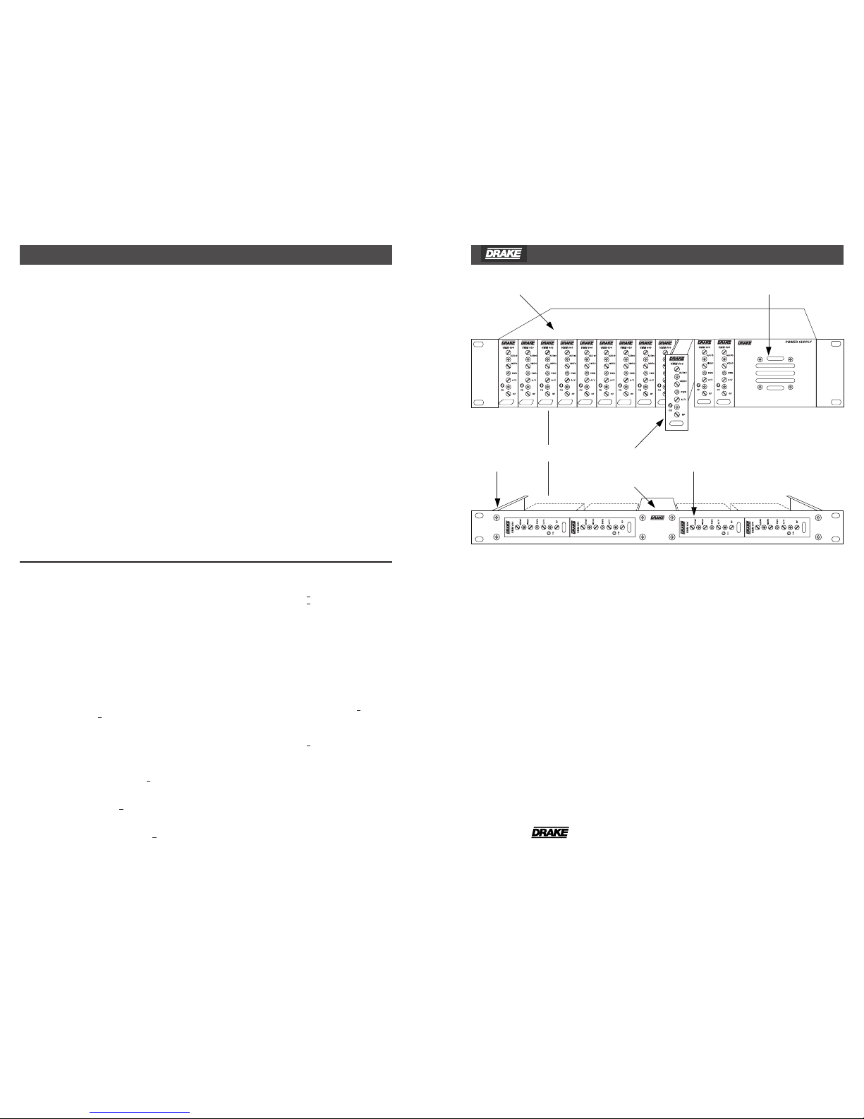
The R.L. Drake VMM 600/VMM 860 Video
Modulator System is a professional quality
modular headend system designed to optimize
rack space. Up to 12 VMM 600 and/or
VMM 860 modulators can be racked alongside
a single power supply in the Drake 12 position
rack mount or up to 4 modulators can be racked
in the 4 position rack mount. Either model is a
high quality, fixed channel heterodyne audio/
video modulator.
The VMM 600 provides a modulated visual and
RF carrier output on any single VHF channel
2-13; Lowband channel A8; Midband channel
A-I and A5-A1; Superband channel J-W;
Hyperband channel AA-ZZ and AAA-XXX
(CATV 63-86) or UHF channel 14-35.
Aeronautical channels are offset positive with
a tolerance of ±5 kHz as required by FCC rules.
The VMM 860 provides a modulated visual and
RF carrier output on any single Hyperband
channel 87-135 or UHF channel 36-69.
12 POSITION RACK MOUNT POWER SUPPLY
® VMM 600/VMM 860 VIDEO MODULATOR SYSTEM 1
4
WARRANTY AND SPECIFICATIONS
® is a registered trademark of the R.L. Drake Company
© Copyright 2005 R.L. Drake Company P/N: 3852631C-04-2005
RF
Frequency Range:
VMM600-
VMM860-
Output Level:
Output Impedance:
A/V Ratio:
Frequency Stability:
Intercarrier Frequency:
FCC Frequency Offsets:
Spurious Outputs:
54 to 1000 MHz
Broadband Noise:
VIDEO
Input level for 87.5%
modulation:
Input Impedance:
Frequency Response:
Video S/N:
4 POSITION
RACK MOUNT
POWER SUPPLY
OR
VMM 600/VMM 860 MODULAR
SINGLE-CHANNEL MODULATORS
®
Aural/Visual (A/V) ratios should be held to
-15 dB or less. The output ‘RF’ and ‘A/V
(Ratio)’ controls are used respectively to make
these adjustments.
RACK MOUNTING
Adequate ventilation is very important in
multi-channel installations. Units should be
spaced apart by at least one panel height
wherever possible, and some air movement is
advisable in enclosed rack cabinets.
Excessive heat will shorten component life and
modulator performance will be degraded
without proper cooling.
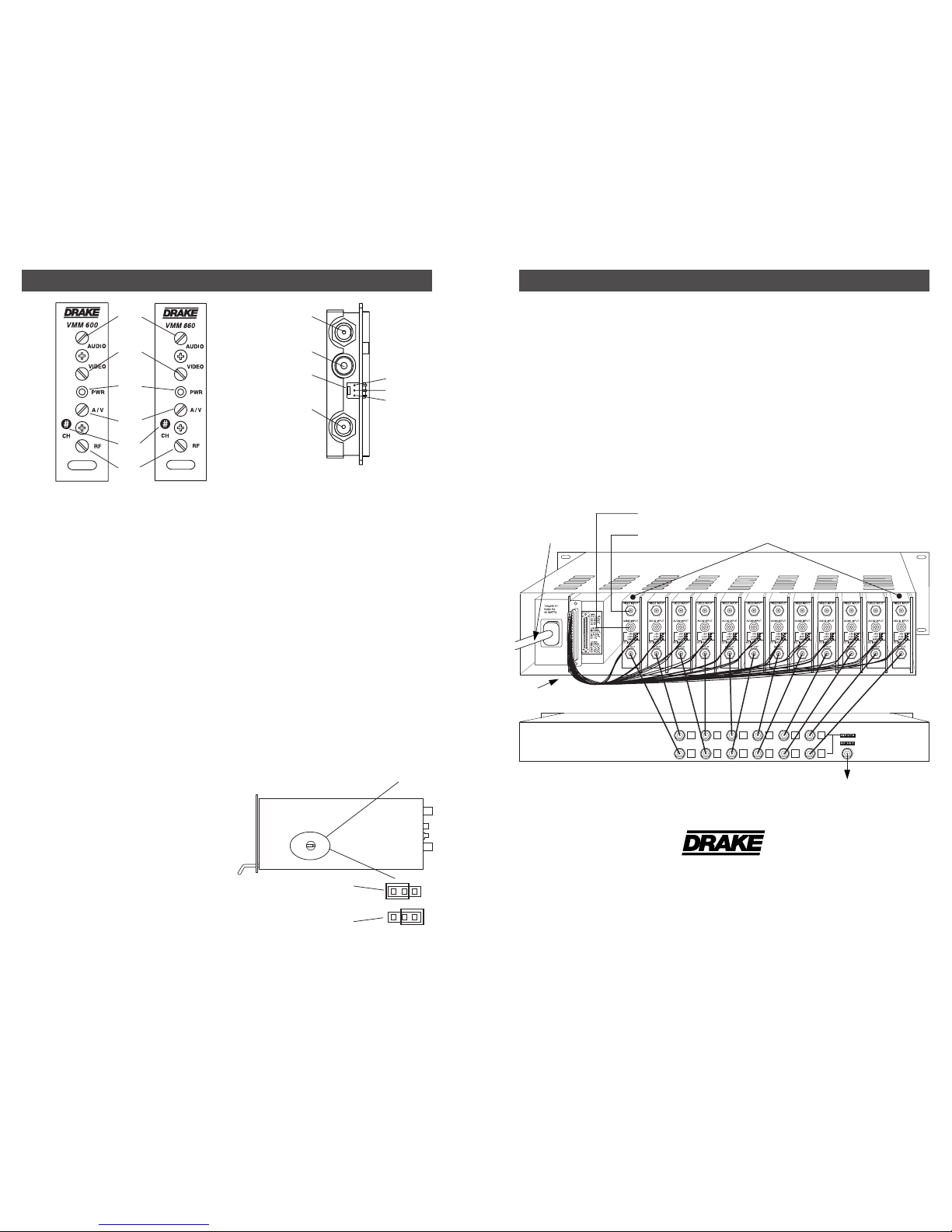
CONNECTIONS AND CONTROLS
All connections to and from each modulator
are made through the rear panel. Figure 3
illustrates an installation with 12 modulator units
combined through a passive signal combiner.
Additional channels can be added by using
additional VMM 600 or VMM 860 modulators
and either multi-port combiners or
combinations of two-port combiners.
INSTALLATION NOTES
Level adjustment provides optimum
performance in multi-channel installations. The
modulator outputs should be checked
periodically with a spectrum analyzer to
maintain a ±1 dB variation of adjacent
channel carriers.
VMM 600's/VMM 860's
AUDIO INPUTS
VIDEO INPUTS
AC POWER
CORD
DC POWER
CABLE
F1
F2
F3
F4
F5
F6
R1 - VIDEO INPUT Connector
This is the baseband video input to the IF
circuits. This input accepts baseband input
thru 4.2 MHz video at levels from 0.7 Vp-p to
1.5 Vp-p.
R2 - AUDIO INPUT Connector
This is an unbalanced audio input to the IF
circuits. This “RCA” (phono) connector input
accepts baseband thru 15 kHz audio at a
nominal level of 250 mV RMS (approximately
0 dBm). NOTE: An externally accessible test
point jumper defeats the audio pre-emphasis
for stereo capability.
R3 - DC INPUT Connector
This 3-pin connector (Male) accepts the
appropriate mating DC power cable. Observe
proper orientation and wiring.
R4 - RF OUTPUT Connector
This is the modulator output.
INTERNAL JUMPER
INSTALLATION 3
2
FRONT PANEL DESCRIPTION REAR PANEL DESCRIPTION
R.L. DRAKE COMPANY
230 INDUSTRIAL DRIVE
FRANKLIN, OHIO 45005 U.S.A.
CUSTOMER SERVICE AND PARTS TELEPHONE:
+1 (937) 746-6990
TELEFAX:
+1 (937) 806-1576
WORLD WIDE WEB SITE: http://www.rldrake.com
Figure 3
Figure 1 Figure 2
R1
R2
R3
R4
AUDIO PRE-EMPHASIS
(On) MONO
AUDIO PRE-EMPHASIS
(Off) STEREO w/MMTS20
SYSTEM OUT
RF COMBINER
F1 - AUDIO Level Control
The setting of this screwdriver adjustment
determines the peak aural carrier deviation.
Clockwise rotation increases the carrier
deviation.
F2 - VIDEO Level Control
The setting of this screwdriver adjustment
determines the video modulation level.
Clockwise rotation increases the modulation
depth.
F3 - POWER Indicator
Lights when the unit is connected to the
required source of DC power via the rear panel
DC INPUT connector.
F4 - A/V Ratio Control
This screwdriver adjustment varies the level of
the aural carrier over a range from 12 to 19 dB
below the visual carrier. The aural carrier
should be adjusted to approximately 15 dB
below the visual carrier (normal operation).
Clockwise rotation increases the aural carrier
level and thus decreases the A/V ratio.
F5 - "CH#" (Channel)
The modulator is factory aligned to the
channel number indicated.
F6 - RF Output Level
This screwdriver adjustment permits
decreasing the RF output level approximately
12 dB below its specified output level as the
control is rotated counterclockwise. The
maximum output level is set with the
adjustment fully clockwise.
+5V
+12V
GND
 Loading...