

Drake VMM806AG Instruction Manual
8
WARRANTY AND SPECIFICATIONS
THREE YEAR LIMITED WARRANTYTHREE YEAR LIMITED WARRANTY
THREE YEAR LIMITED WARRANTY
THREE YEAR LIMITED WARRANTYTHREE YEAR LIMITED WARRANTY
R.L. DRAKE COMPANY warrants to the original purchaser this product shall be free from defects in material or workmanship for three (3)
years from the date of original purchase.
During the warranty period the R.L. DRAKE COMPANY or an authorized Drake service facility will provide, free of charge, both parts and
labor necessary to correct defects in material and workmanship. At its option, R.L. DRAKE COMPANY may replace a defective unit.
To obtain such warranty service, the original purchaser must:
(1)(1)
(1) Retain invoice or original proof of purchase to establish the start of the warranty period.
(1)(1)
(2)(2)
(2) Notify the R.L. DRAKE COMPANY or the nearest authorized service facility, as soon as possible after discovery of a possible defect,
(2)(2)
of:
(a) the model and serial number,
(b) the identity of the seller and the approximate date of purchase; and
(c) A detailed description of the problem, including details on the electrical connection to associated equipment and the list of such
equipment.
(3)(3)
(3) Deliver the product to the R.L. DRAKE COMPANY or the nearest authorized service facility, or ship the same in its original container
(3)(3)
or equivalent, fully insured and shipping charges prepaid.
Correct maintenance, repair, and use are necessary to obtain proper performance from this product. Therefore carefully read the Instruction
Manual. This warranty does not apply to any defect that R.L. DRAKE COMPANY determines is due to:
(1)(1)
(1) Improper maintenance or repair, including the installation of parts or accessories that do not conform to the quality and specifications
(1)(1)
of the original parts.
(2)(2)
(2) Misuse, abuse, neglect or improper installation.
(2)(2)
(3)(3)
(3) Accidental or intentional damage.
(3)(3)
All implied warranties, if any, including warranties of merchantability and fitness for a particular purpose, terminate three (3) years from the
date of the original purchase.
The foregoing constitutes R.L. DRAKE COMPANY’S entire obligation with respect to this product, and the original purchaser shall have no
other remedy and no claim for incidental or consequential damages, losses or expenses. Some states do not allow limitations on how long
an implied warranty lasts or do not allow the exclusions or limitation of incidental or consequential damages, so the above limitation and
exclusion may not apply to you.
This warranty gives you specific legal rights and you may also have other rights which vary from state to state. This warranty shall be
construed under the laws of Ohio.
® VMM806AG VIDEO MODULATOR 1
12 POSITION RACK MOUNT POWER SUPPLY
POWER SUPPLY
BC
TV
5
POWER
ERROR
VIDEO
A/V
RF
AUDIO
2
CATV
CATV
+100
AUDIO
VIDEO
PWR
A/V
#
CH
RF
4 POSITION
RACK MOUNT
VMM806AG
MODULATOR MODULATOR MODULATORMODULATOR MODULATOR MODULATOR
AUDIO
VIDEO
PWR
A/V
#
CH
RF
AUDIO
AUDIO
VIDEO
VIDEO
PWR
PWR
A/V
A/V
#
#
CH
#
CH
CH
RF
RF
OR
MODULATOR MODULATOR MODULATORMODULATOR MODULATOR
AUDIO
AUDIO
AUDIO
VIDEO
VIDEO
PWR
PWR
A/V
A/V
#
CH
RF
RF
AUDIO
AUDIO
VIDEO
PWR
A/V
#
CH
RF
VMM806AG
VIDEO
VIDEO
POWER
ERROR
PWR
PWR
AUDIO
A/V
A/V
#
CH
VIDEO
#
CH
2
5
RF
RF
CATV
BC
CATV
TV
+100
A/V
RF
VMM806AG and other compatible
AUDIO
AUDIO
VIDEO
VIDEO
PWR
PWR
A/V
A/V
#
#
CH
CH
RF
RF
modular units
POWER SUPPLY
BC
TV
5
POWER
ERROR
VIDEO
A/V
RF
AUDIO
2
CATV
VMM806AG
CATV
+100
BC
TV
5
POWER
ERROR
VIDEO
A/V
RF
AUDIO
2
CATV
CATV
+100
VMM806AG
BC
TV
5
POWER
ERROR
VIDEO
A/V
RF
AUDIO
2
CATV
VMM806AG
CATV
+100
®
R.L. DRAKE COMPANY
230 INDUSTRIAL DRIVE
CUSTOMER SERVICE AND PARTS TELEPHONE:
WORLD WIDE WEB SITE: http://www.rldrake.com
© Copyright 2003 R.L. Drake Company P/N: 3852416H-12-2003 Printed in U.S.A.
FRANKLIN, OHIO 45005 U.S.A.
+1 (937) 746-6990
TELEFAX:
+1 (937) 743-4576
® is a registered trademark of the R.L. Drake Company
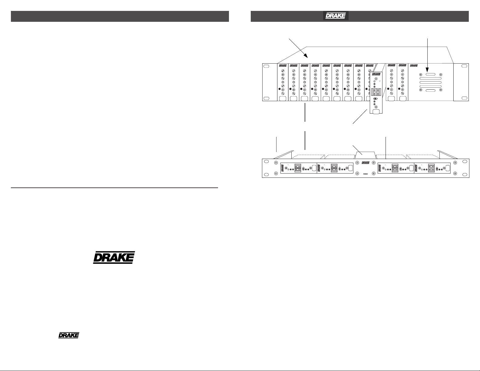
The R.L. Drake Video Modulator System is a
professional quality modular headend system
designed to optimize rack space. An
assortment of up to (12) modular units, such as
the fixed channel series of modulators, or agile
modulators, or compatible audio/video products
can be racked alongside a single power supply
in the Drake12 position rack mount. The RMM4
rack mount accepts up to (4) modular units.
The R.L. Drake VMM806AG Audio-Video
Modulator is a high quality, vestigial sideband
unit with synthesized visual and aural carriers.
The frequency agile VMM806AG allows front
panel pushwheel switch selection of standard
CATV channels 2 through 125, or VHF/UHF TV
channels 2 through 69. Aeronautical channels
are offset positive with a tolerance of ±5 kHz as
required by FCC rules.
The heterodyne conversion system, in
conjunction with the use of a SAW filter,
ensures optimum vestigial selectivity for
adjacent channel headends.
An optional FCC predistortion SAW response is
also available for the VMM806AG.
The modulator is designed to accept any
standard audio/video source such as NTSC
video and audio baseband signals from a
satellite receiver, TV camera, videotape
recorder, TV demodulator, or similar signal
source.
The modulator is designed to accept standard
(negative sync) polarity video at 0.6 to 1.5 Vp-p
level. All level controls are located on the front
panel for ease of operation. Output level is
+45 dBmV and is adjustable over a 15 dB
range.
Field-defeatable audio pre-emphasis allows
transmission of BTSC encoded baseband
stereo audio signals using the Drake stereo
encoder. The AUDIO INPUT can also accept a
4.5 MHz audio modulated carrier by changing
internal jumpers.
2
FRONT PANEL CONTROLS and INDICATORS
REAR PANEL CONNECTIONS / INTERNAL JUMPERS 3
F1
F2
F3
F4
F5
CATV
+100
F6
F7
F1 - POWER/ERROR Indicator
Lights when the unit is connected to the
required source of DC power via the rear panel
DC INPUT connector. A flashing condition
indicates an invalid channel setting or other
conditions that would cause the unit to operate
on an invalid channel. The RF output is
switched off for flashing (ERROR) conditions.
F2 - AUDIO Level Control
The setting of this screwdriver adjustment
determines the aural carrier deviation. Clockwise rotation increases the carrier deviation.
F3 - VIDEO Level Control
The setting of this screwdriver adjustment
determines the video modulation level.
Clockwise rotation increases the modulation
depth.
F4 - Channel Number Switch
Sets the desired operating channel for standard
CATV channels 02 through 125 or Broadcast
TV channels 02 through 69. See also Item F5
which sets the type of channel (CATV or
Broadcast TV) and sets the leading “1” for
CATV channels 100 through 125.
VMM806AG
POWER
ERROR
AUDIO
VIDEO
2
5
CATV
BC
TV
A/V
RF
Figure 1
F5 - Mode Switch
Sets the type of channel, CATV or Broadcast
TV (“BC TV”). The first position of the switch
(“+100”) sets a leading “1” for CATV channels
100 through 125. See also Item F4 for setting
the channel number.
For example: For example:
Setting for CATV Setting for CATV
channel "125"- channel "25"-
2
5
CATV
+100
CATV
BC
TV
CATV
+100
F6 - A/V Ratio Control
This screwdriver adjustment varies the level of
the aural carrier over a range from 11 to
18 dB below the visual carrier. The aural carrier
should be adjusted to approximately 15 dB
below the visual carrier (normal operation).
Clockwise rotation increases the aural carrier
level.
2
CATV
R1
R2
R3
R4
Figure 2
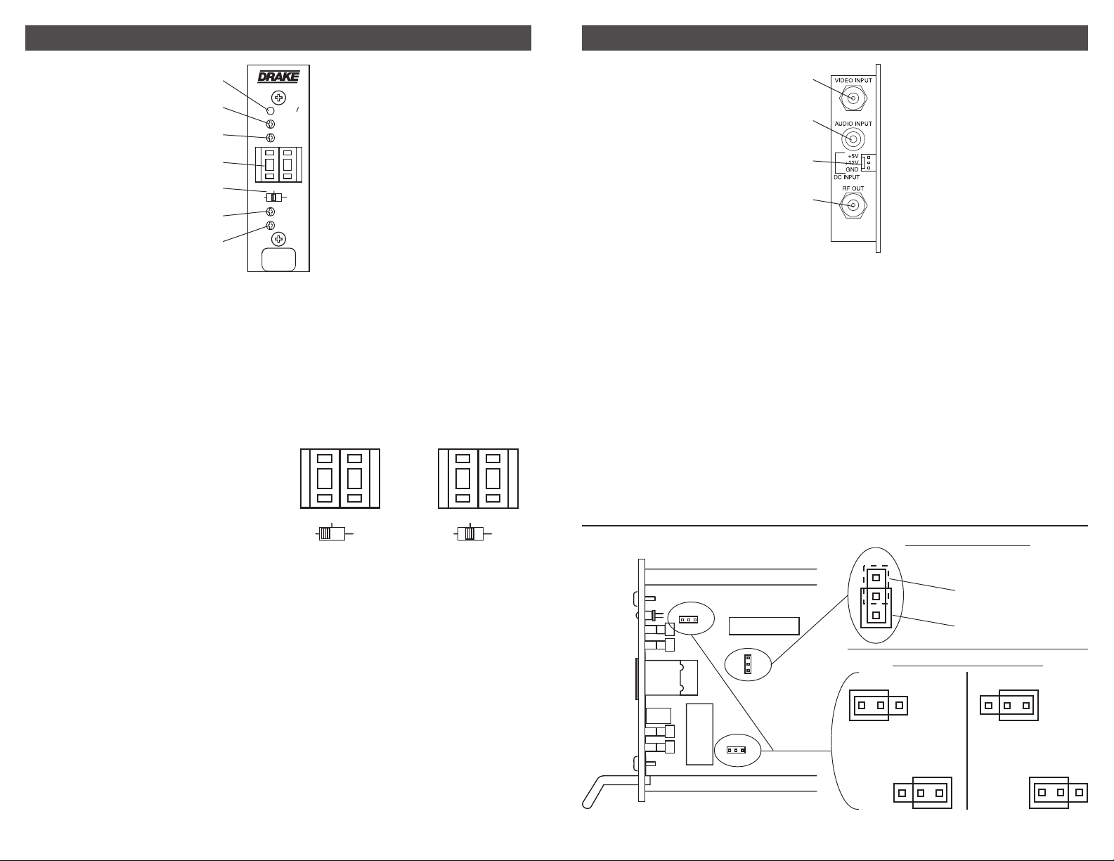
R1 - VIDEO INPUT Connector
This is the baseband video input to the IF
circuits. This input accepts baseband input
levels from 0.6 Vp-p to 1.5 Vp-p.
4.5 MHz Audio Input: This AUDIO INPUT can
also accept a 4.5 MHz audio modulated carrier
by reconfiguring two specified internal jumper
settings. Required 4.5 MHz input level is
+40 dBmV ±2 dB. Some stereo generators or
R2 - AUDIO INPUT Connector
This is an unbalanced audio input to the IF
circuits. This “RCA” (phono) connector input
satellite receivers provide audio output in a
4.5 MHz audio modulated carrier format. See
the illustration on this page.
accepts baseband audio from 100 mVrms to
3 Vrms levels.
NOTE: An internally selected test point jumper
defeats the audio pre-emphasis for stereo
5
capability. See the illustration on this page.
R3 - DC INPUT Connector
This 3-pin connector (Male) accepts the
appropriate mating DC power cable. Observe
proper orientation and wiring.
R4 - RF OUTPUT Connector
This is the modulator output.
BC
TV
A.
B.
PRE-EMPHASIS / FLAT:
AUDIO - FLAT
AUDIO PRE-EMPHASIS
(factory setting)
A.
AUDIO INPUT CONNECTOR:
F7 - RF Output Level
This screwdriver adjustment permits decreasing
the RF output level a minimum of 15 dB as the
control is rotated counterclockwise. Set the
control for a +45 dBmV output level .
Figure 3
C.
B.
AUDIO INPUT -
Baseband audio,
(factory setting)
C.
B.
AUDIO INPUT -
4.5 MHz modulated
carrier
C.
 Loading...