

Drake VMM600 User Manual
®
VMM 600/VMM 806 VIDEO MODULATOR SYSTEM 1
OR
4 WARRANTY AND SPECIFICATIONS
THREE YEAR LIMITED WARRANTY
R.L. DRAKE HOLDINGS LLC warrants to the original purchaser this product shall be free from defects in material or
workmanship for three (3) years from the date of original purchase.
During the warranty period R.L. DRAKE HOLDINGS LLC or an authorized Drake service facility will provide, free of charge,
both parts and labor necessary to correct defects in material and workmanship. At its option, R.L. DRAKE HOLDINGS LLC may
replace a defective unit.
To obtain such a warranty service, the original purchaser must:
1. Retain invoice or original proof of purchase to establish the start of the warranty period.
2. Notify R.L. DRAKE HOLDINGS LLC or the nearest authorized service facility, as soon as possible after discovery of a
possible defect, of:
Correct maintenance, repair, and use are important to obtain proper performance from this product. Therefore carefully read the
Instruction Manual. This warranty does not apply to any defect that R.L. DRAKE HOLDINGS LLC determines is due to:
quality and specifications of the original parts.
All implied warranties, if any, including warranties of merchantability and fitness for a particular purpose, terminate three (3)
years from the date of the original purchase.
The foregoing constitutes R.L. DRAKE HOLDINGS LLC'S entire obligation with respect to this product, and the original
purchaser shall have no other remedy and no claim for incidental or consequential damages, losses or expenses. Some states
do not allow limitations on how long an implied warranty lasts or do not allow the exclusions or limitation of incidental or
consequential damages, so the above limitation and exclusion may not apply to you.
This warranty gives you specific legal rights and you may also have other rights which vary from state to state. This warranty
shall be construed under the laws of Ohio.
a) the model and serial number,
b) the identity of the seller and the approximate date of purchase; and
c) A detailed description of the problem, including details on the electrical connection to associated equipment and
the list of such equipment.
3. Deliver the product to R.L. DRAKE HOLDINGS LLC or the nearest authorized service facility, or ship the same
in its original container or equivalent, fully insured and shipping charges prepaid.
1. Improper maintenance or repair, including the installation of parts or accessories that do not conform to the
2. Misuse, abuse, neglect or improper installation.
3. Accidental or intentional damage.
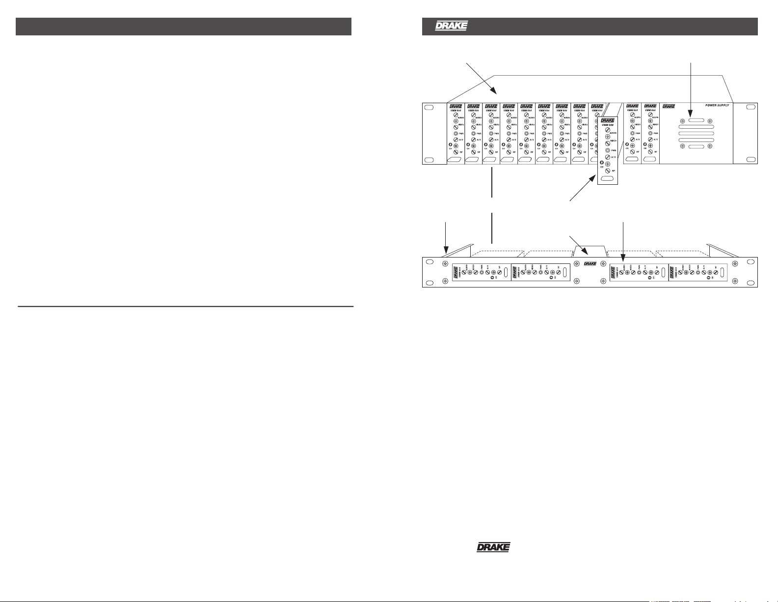
12 POSITION RACK MOUNT POWER SUPPLY
4 POSITION
RACK MOUNT
VMM 600/VMM 806 MODULAR
SINGLE-CHANNEL MODULATORS
POWER SUPPLY
SPECIFICATIONS
Frequen cy Range:
Power Level Range: 10 dB continiously adjustable
Carrier-to-Noise: 63 dB
Broadband Noise: -90 dBc
Spurious Outputs: -66 dBc
Aural/Visual Carrier Ratio: -11 to - 19 dB
4.5 MHz Aural Inter-carrier
Freq. Tolerance: ± 250 Hz; 32 to 122 °F
Frequency Response: 1.0 dB Peak to Valley
Peak to Peak Video-to-RMS
Signal-to-Noise Ratio: 65 dB
Differential Phase: 2.0 degree
Differential Gain: 2.0%
RF
VMM600-
VMM806-
Impedance: 75 Ohms
Return Loss: 15 dB
Power Level: +45 dBmV
Connector: “F” Female
Impedance: 75 Ohms
Return Loss: 20 dB
Input Level: 1.0 volt Peak to Peak
Hum Ratio: 64 dB
54-600 MHz.
Factory set to one of the following
channels:
Cable Channels 2-86, 95-99
600-806 MHz.
Factory set to one of the following
channels:
Cable Channels 87-125
VIDEO
C/L Delay: Per FCC Requirements
AUDIO
Input Impedance: Greater than 10k Ohms,
Frequency Range: 50 Hz to 12 kHz
Frequency Response: ± 0.5 dB
Total Harmonic Distortion: 1% @ 25 kHz deviation
Signal-to-Noise Ratio: 70 dB
Operating Temperature:
Specifications subject to change without notice or obligation.
Connector: RCA
Input Level: 0.5 to 4.0 volt peak-to-peak
GENERAL
DC Power Input:
unbalanced
(constant AGC range)
+12 VDC @ 240 mA,
+5 VDC @ 35 mA,
0°C to +50°C.
Size:
1"W x 3.5" H x 7.78"D.
11 oz.
Weight:
The R.L. Drake VMM 600/VMM 806 Video
Modulator System is a professional quality
modular headend system designed to optimize
ra ck sp ace. Up to 12 VMM 600 and /or
VMM 806 modulators can be racked alongside
a single power supply in the Drake 12 position
rack mount or up to 4 modulators can be racked
in th
e 4 position rack mount. Either model is a
high quality, fixed channel heterodyne audio/
video modulator.
The VMM 600 provides a modulated visual and
RF carrier output on any single channel
95-99;
Aeronautical channels are offset positive
2-86,
with a tolerance of ±5 kHz as required by FCC
rules.
The VMM 806 provides a modulated visual and
RF carrier output on any single channel
87-125.
® is a registered trademark of the R.L. Drake Holdings LLC
© Copyright 2012 R.L. Drake Holdings LLC P/N: 651232000A
10072XX/10073XX
Printed in China
Th e het ero dyne co nver sio n sys tem , in
conjunction with the use of a SAW filter,
insu res optim um vesti gial sele ctivi ty for
adjacent channels.
The modulators are designed to accept any
standard audio/video source such as NTSC
video and audio baseband signals from a
sate ll ite receiver, T V c am era, vid eo tape
recorder, TV demodulator, or similar signal
source.
The modulators have Audio AGC that eliminates
variations in loudness level that may be present
among various program sources.
Th e mo dulators acc ept sta nda rd ( syn c
negative) polarity video at a 0.7 to 2.5 Vp-p
l level controls are located on the front
level. Al
panel for ease of operation. Output level of
+45 dBmV is typical and is adjustable from
+30 to +45 dBmV.
Field-defeatable audio pre-emphasis enables
passing of BTSC encoded standard baseband
ster eo aud io sig na ls.
Rev:120917
INSTALLATION 3
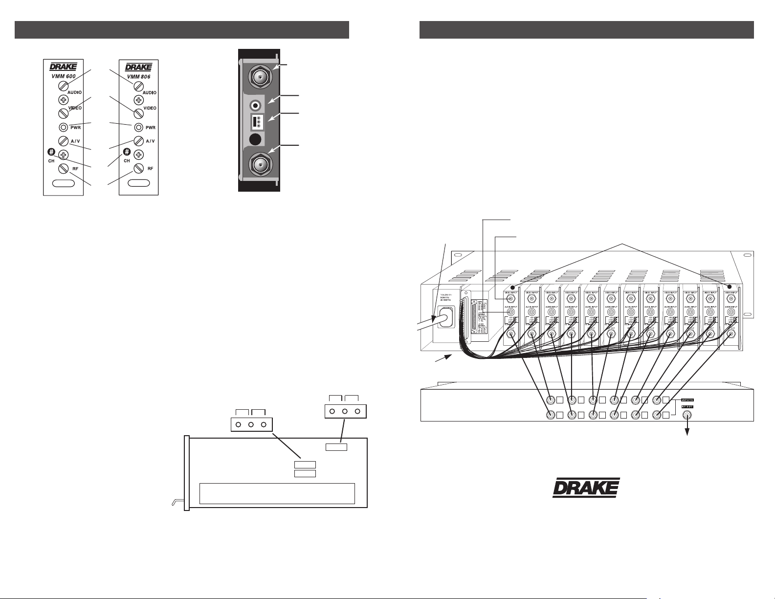
2 FRONT PANEL DESCRIPTION REAR PANEL DESCRIPTION
Figure 3
2
Figure 1 Figure 2
F1
F2
F3
F4
F5
F6
F1 - AUDIO Level Control
This screwdriver adjustment varies the peak
aural carrier deviation. Clockwis e rotation
increases the c arrier deviation.
F2 - VIDEO Level Control
This screwdriver adjustment varies the video
modula tio n lev el. Clockwise rotation
increases the modulation depth.
F3 - POWER Indicator
Lig hts when the unit is connect ed t o the
required source of DC power via the rear panel
DC INPUT connector.
F4 - A/V Ratio Control
This screwdriver adjustment varies the level of
the aural carr
ier over a range from 11 to 19 dB
below the visual carrier. The aural carrier
should be adjusted to approximately 15 dB
below the visual carrier (normal operation).
Clockwise rotation increases the aural carrier
level and thus decreases the A/V ratio.
F5 - "CH#" (Channel)
Th e mo du lat or is fact ory align ed to the
channel number indicated.
F6 - RF Output Level
This screwdriver adjustment varies the RF
Output level from approximately 35-45 dBmV.
maximum output level is set with the
The
adjustment fully clockwise.
R1 - VIDEO INPUT Connector
This input accepts baseband input thru
4.2 MHz video at levels from 0.7 Vp-p to
1.5 Vp-p.
R2 - AUDIO INPUT Connector
This “RCA” (phono) connector input accepts
baseband audio at a nominal level of 0.5 VPP.
NOTE: two internal jumpers can be configured
to defeat the audio pre-emphasis or stereo
capability. Top cover must be opened to access.
R3 - DC INPUT Connector
This 3-pi n c on ne ctor (Male) accepts the
appropriate mating DC power cable. Observe
proper orientation and wiring.
R4 - RF OUTPUT Connector
This is the modulator RF output
STEREO MONO
Internal Jumper Settings
R1
R2
R3
R4
PRE-EMPHASIS
J3
DISABLE ENABLE
J4
CONNECTIONS AND CONTROLS
All connections to and from each modulator
are made through the rear panel. Figure 3
illustrates an installation with 12 modulator units
combined through a passive
signal combiner.
Additional channels can be added by using
additional VMM 600 or VMM 806 modulators
an d ei the r mult i-p ort c ombin ers or
combinations of two-port combiners.
INSTALLATION NOTES
Level ad jus tme nt prov ide s opt imu m
performance in multi-channel installations. The
mo dul ato r outp uts sho uld be c hecked
peri od ic al ly with a spectrum ana ly zer to
ma int ain a ±1 dB vari ati on of ad jac ent
channel carriers.
AUDIO INPUTS
AC POWER
CORD
DC POWER
CABLE
VIDEO INPUTS
RF COMBINER
R.L. Drake Holdings LLC
710 Pleasant Valley Drive
Customer Service and Parts Telephone: +1 (937) 746-6990
Fax: +1 (937) 806-1510 www.rldrake.com
Springboro, Ohio 45066
Aural/Visual (A/V) ratios should be held to
-15 dB or less. The output ‘RF’ and ‘A/V
(Ratio)’ controls are used respectively to make
these adjustments.
RACK MOUNTING
Adequate ventilation is very important in
multi-channel installations. Units should be
spaced apart by at least one panel height (1.75”)
wherever possible, and some air movement is
advisable in enclosed rack cabinets.
Excessive heat will shorten component life and
modulator performance will be degraded
without proper cooling.
VMM 600's/VMM 806's
SYSTEM OUT
®
 Loading...