

DRAKE VMD860AS, VMR860AG, VMR860AS, VMD860AG Instruction Manual
2
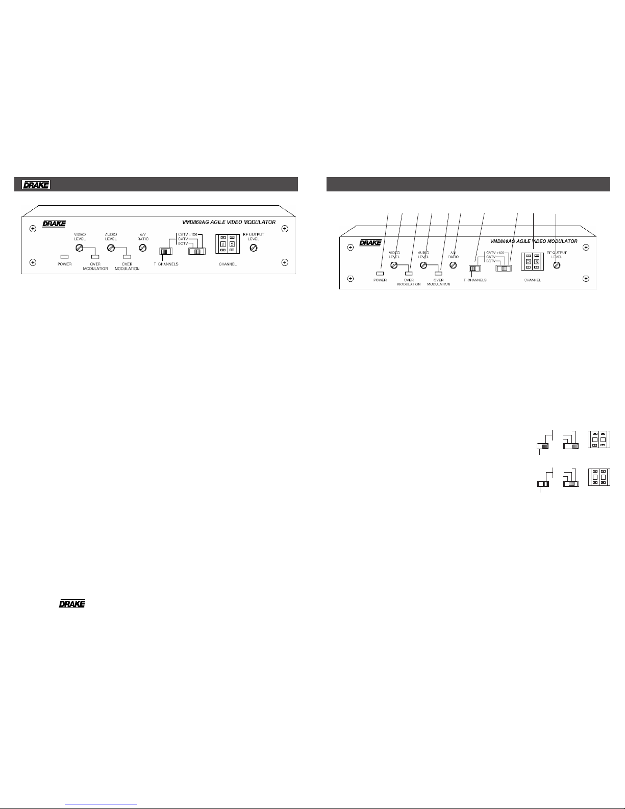
FRONT PANEL CONTROLS and INDICATORS
® is a registered trademark of the R.L. Drake Company
© Copyright 2007 R.L. Drake LLC P/N: 3852411E-04-2007 Printed in the U.S.A.
The modulators are designed to accept any
standard audio/video source such as NTSC
video and audio baseband signals from a
satellite receiver, TV camera, videotape
recorder, TV demodulator, or similar signal
source. The VMD860AS and VMR860AS can
accept stereo audio inputs and produce a
BTSC stereo audio signal.
When stereo audio is required, the preferred
method of providing a BTSC stereo signal is to
use the VMD860AS or VMR860AS model. No
special setup or test equipment is required.
Also, field-defeatable audio pre-emphasis in
the AG models allows transmission of BTSC
encoded baseband stereo audio signals from
an external BTSC stereo encoder, such as the
Drake MMTS20. Optimum performance requires
proper test equipment for setup with external
BTSC encoders.
The AG models will accept either mono or
stereo inputs and output a mono audio signal
with left and right inputs being summed in the
modulator.
The modulators are designed to accept
standard (negative sync) polarity video at 0.6
to 1.5 Vp-p level. All level controls are located
on the front panel for ease of operation. Audio
and video overmodulation indicators are
provided. Output level is +45 dBmV and is
adjustable downward.
FCC predistortion is provided in the video IF.
This instruction manual also is applicable to the
VMD860AS, VMR860AG, and VMR860AS.
The AS models include a built-in BTSC stereo
audio encoder to provide stereo audio.
The VMR models are electrically identical to the
VMD units except that they are designed for
19" rack mounting.
In this manual, only the VMD860AG model is
discussed except where there are differences. Any differences will be explained.
The R.L. Drake VMD860AG family of AudioVideo Modulators includes high quality, vestigial
sideband units with synthesized visual and
aural carriers. The frequency agile units allow
front panel pushwheel switch selection of
standard CATV channels 2 through 135, CATV
subband channels, T7 through T14, or VHF/
UHF TV channels 2 through 69. Additionally,
IRC or HRC CATV channel plans may be
selected after moving an internal jumper.
Aeronautical channels are offset positive with
a tolerance of ±5 kHz as required by FCC
rules.
The heterodyne conversion system, in
conjunction with the use of a SAW filter,
ensures optimum vestigial selectivity for
adjacent channel headends.
Broadband noise and in-channel noise are
reduced to a very low levels to provide
excellent performance in multichannel CATV
headend environments.
® VMD860AG VIDEO MODULATOR 1
Figure 1
F7 -T CHANNEL Switch
Set this switch to the "T" channel setting to
enable "T" channel coverage. Use the Channel
Number switch (F9) to select 7 - 14. For normal
CATV or broadcast TV channels, this switch
must be set to the right to enable selection by
the mode switch (F8).
F8 - Mode Switch
Sets the type of channel, CATV or Broadcast
TV (“BCTV”). This switch does not function if
switch (F7) is in the "T" channel position. The
last position of the switch (“+100”) sets a
leading “1” for CATV channels 100 through 125.
See Item (F9) for setting the channel number.
CATV +100
CATV
BCTV
CHANNEL
T CHANNELS
25
CATV +100
CATV
BCTV
CHANNEL
T CHANNELS
25
F9 - CHANNEL Number Switch
Sets the desired operating channel for standard
CATV channels 02 through 135, "T" channels
T7 through T14, or Broadcast TV channels 02
through 69. See Item (F8) which sets the type
of channel (CATV or Broadcast TV) and sets
the leading “1” for CATV channels 100 through
125.
F10 - RF OUTPUT LEVEL
This screwdriver adjustment permits decreasing
the RF output level a minimum of 10 dB as the
control is rotated counterclockwise. Set the
control for a desired output level.
F1 F2 F3 F4 F5 F6 F7 F8 F9 F10
Example 1:
Setting for CATV
channel "125"-
Example 2:
Setting for CATV
channel "25"-
F1 - POWER/Error Indicator
Lights when the unit is connected to the
required source of DC power via the rear panel
DC INPUT connector. A flashing condition
indicates an invalid channel setting or other
conditions that would cause the unit to operate
on an invalid channel. The RF output is
switched off for flashing (ERROR) conditions.
F2 - VIDEO Level Control
The setting of this screwdriver adjustment
determines the video modulation level.
Clockwise rotation increases the
modulation depth.
F3 - Video OVER MODULATION LED
With a video input applied, adjust (F2) until this
indicator just illuminates, then set just below
this point.
F4 - AUDIO Level Control
The setting of this screwdriver adjustment
determines the aural carrier deviation. Clockwise rotation increases the carrier deviation.
F5 - Audio OVER MODULATION LED
With audio applied, adjust (F4) until this
indicator just illuminates on peaks.
F6 - A/V RATIO Control
This screwdriver adjustment varies the level of
the aural carrier over a range from 12 to
20 dB below the visual carrier. The aural
carrier should be adjusted to approximately 15
dB below the visual carrier (normal operation).
Clockwise rotation increases the aural
carrier level.
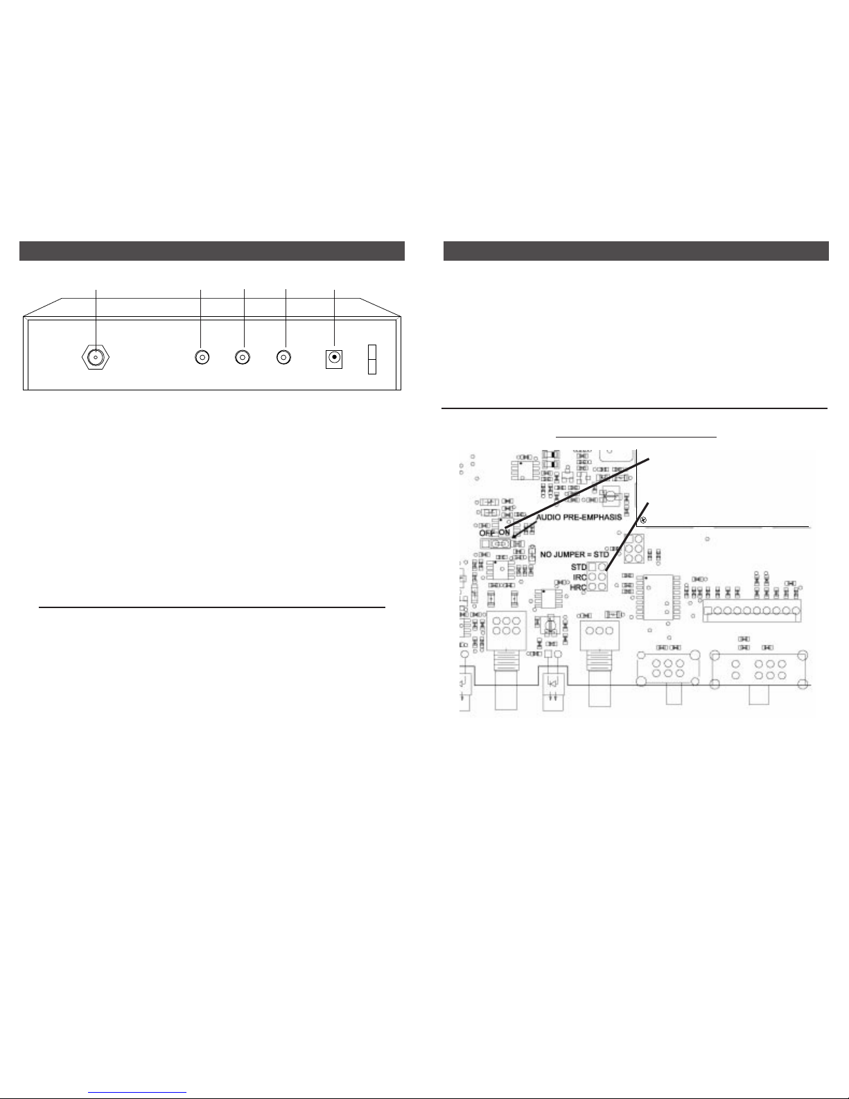
3 REAR PANEL CONNECTIONS
R1 R2 R3 R4 R5
R1 - RF OUTPUT Connector
This is the modulator output.
R2 and R3 - AUDIO INPUT Connectors
These "RCA" (phono) connector inputs accept
baseband audio from 250 mVrms to 3 Vrms
levels. NOTE: In the AG models, an internally
selected jumper can defeat the audio preemphasis for use with a stereo encoder. See
Diagram on page 4.
For AG mono models, the inputs from the left
and right jacks are internally summed. Input
can be from a stereo source to both inputs or
from a mono source to just one of the inputs.
For the AS stereo models, R2 and R3 are the
left and right stereo channel inputs. A mono
source connected to an AS stereo unit should
be input to both connectors using a "Y" cable.
R4 - VIDEO INPUT Connector
This is the baseband video input to the IF
circuits. This input accepts baseband input
levels from 0.6 Vp-p to 1.5 Vp-p.
R5 - POWER / DC INPUT Connector
This connector accepts the appropriate mating
DC power cable from the supplied AC adapter.
Figure 2
MOUNTING
Adequate ventilation is very important in
multichannel installations. Units should be
spaced apart by at least one panel height
wherever possible, and some air movement is
mandatory in enclosed rack cabinets.
Excessive heat will shorten component life and
modulator performance will be degraded without
proper ventilation.
INSTALLATION NOTES
Level adjustment provides optimum
performance in multichannel installations.
The modulator outputs should be checked
periodically with a spectrum analyzer or signal
strength meter to maintain a ±1 dB variation of
adjacent channel carriers. Aural/Visual (A/V)
ratios should be held to -15 dB or less. The
output ‘RF’ and ‘A/V (Ratio)’ controls are used
respectively to make these adjustments.
4
SETTING THE INTERNAL JUMPERS
JUMPER FUNCTIONS
Refer to the INTERNAL JUMPER FUNCTIONS
diagram for a brief explanation of the two
jumpers used in the jumper settings.
Refer to the INTERNAL JUMPER SETTINGS
Diagram for proper jumper placement of the
desired mode.
ACCESSING THE JUMPERS
- First, make certain the unit is disconnected
from its power source.
- Next, remove the four #4 screws from each
side of the top cover. Save the screws for later
reassembly.
- Carefully remove the top cover by lifting it
upward from the chassis. The jumpers are now
accessible for setting as desired.
RF OUT AUDIO IN
LEFT RIGHT
VIDEO IN POWER
INTERNAL JUMPER FUNCTIONS
Front of VMM860AG With Cover Removed
Shown in standard configuration
(no jumper). Add jumper for IRC or
HRC.
Audio Pre-emphasis jumper shown
in the ON position.
 Loading...