

DRAKE VM2860, VM2862 Instruction Manual

®
VM2860/VM2862
Commercial Video Modulator
(For use in NTSC systems)
Instruction Manual
© Copyright 2003 R.L. Drake Company P/N: 3852471C-2-2003 Printed in the U.S.A.
® is a registered trademark of the R.L. Drake Company
2 Cautions Statements
WARNING: TO PREVENT FIRE OR
ELECTRICAL SHOCK DO NOT
EXPOSE TO RAIN OR MOISTURE
¡WARNING!
RISK OF ELECTRIC SHOCK
DO NOT OPEN
WARNING: TO REDUCE THE RISK OF ELECTRIC SHOCK,
DO NOT REMOVE POWER SUPPLY COVERS
NO USER-SERVICEABLE PARTS INSIDE
REFER SERVICING TO QUALIFIED PERSONNEL
An appliance and cart combination should be moved with care. Quick stops,
excessive force and uneven surfaces may cause the appliance and cart combination to overturn.
The lightning flash with arrow head symbol, within an equilateral triangle, is
intended to alert the user to the presence of uninsulated "dangerous voltage"
within the product's enclosure that may be of sufficient magnitude to constitute a
risk of electric shock to persons.
The exclamation point within an equilateral triangle is intended to alert the user to
the presence of important operating and maintenance (servicing) instructions in
the literature accompanying the appliance.
WARNING:
CAUTION:
ATTENTION:
TO REDUCE THE RISK OF FIRE OR ELECTRIC SHOCK, DO NOT EXPOSE THIS
APPLIANCE TO RAIN OR MOISTURE. DO NOT OPEN THE CABINET, REFER SERVICING TO QUALIFIED PERSONNEL ONLY.
TO PREVENT ELECTRIC SHOCK, DO NOT USE THIS (POLARIZED) PLUG WITH AN
EXTENSION CORD RECEPTACLE OR OTHER OUTLET UNLESS THE BLADES CAN BE
FULLY INSERTED TO PREVENT BLADE EXPOSURE.
POUR PREVENIR LES CHOCS ELECTRIQUES, NE PAS UTILISER CETTE FICHE
POLARISEE AVEC UN PROLONGATEUR, UNE PRISE DE COURANT OU UNE AUTRE
SORTIE DE COURANT, SAUF SI LES LAMES PEUVENT ETRE INSEREES A FOND SANS
EN LAISSER AUCUNE PARTIE A DECOUVERT.
Important Safety Instructions
1. Read Instructions—All the safety and operating instructions should be read before the product
is operated.
2. Retain Instructions—The safety and operating instructions should be retained for future
reference.
3. Heed Warnings—All warnings on the product and in the operating instructions should be
adhered to.
4. Follow Instructions—All operating and use instructions should be followed.
5. Cleaning—Unplug this product from the wall outlet before cleaning. Do not use liquid cleaners
or aerosol cleansers. Use a damp cloth for cleaning.
6. Attachments—Do not use attachments that are not recommended by the product manufacturer as they may cause hazards.
7. Water and Moisture—Do not use this product near water—for example, near a bathtub, wash
bowl, kitchen sink or laundry tub; in a wet basement; or near a swimming pool; and the like.
8. Accessories—Do not place this product on an unstable cart, stand, tripod, bracket, or table.
The product may fall, causing serious injury to a child or adult, and serious damage to the product.
Use only with a cart, stand, tripod, bracket, or table recommended by the manufacturer, or sold
with the product. Any mounting of the product should follow the manufacturer's instructions, and
should use a mounting accessory recommended by the manufacturer.
9. A product and cart combination should be moved with care. Quick stops, excessive force, and
uneven surfaces may cause the product and cart combination to overturn.
10. Ventilation—Slots and openings in the cabinet are provided for ventilation and to ensure
reliable operation of the product and to protect it from overheating, and these openings must not
be blocked or covered. The openings should never be blocked by placing the product on a bed,
sofa, rug, or similar surface. This product should not be placed in a built-in installation such as
bookcase or rack unless proper ventilation is provided or the manufacturer's instructions have
been adhered to.
11. Power Sources—This product should be operated only from the type of power source
indicated on the marking label. If you are not sure of the type of power supplied to your home,
consult your product dealer or local power company. For products intended to operate from battery
power, or other sources, refer to the operating instructions.
12. Grounding or Polarization—This product may be equipped with a polarized alternatingcurrent line plug (a plug having one blade wider than the other). This plug will fit into the power outlet
only one way. This is a safety feature. If you are unable to insert the plug fully into the outlet, try
reversing the plug. If the plug should still fail to fit, contact your electrician to replace your obsolete
outlet. Do not defeat the safety purpose of the polarized plug.
Alternate Warnings—If this product is equipped with a three-wire grounding-type plug, a plug
having a third (grounding) pin, the plug will only fit into a grounding-type power outlet. This is a
safety feature. If you are unable to insert the plug into the outlet, contact your electrician to replace
your obsolete outlet. Do not defeat the safety purpose of the grounding-type plug.
12 a. Mise à la terre ou Polarisation—Cet appareil est équipé avec un cordon d'alimentation à
trois fils. Il est a brancher sur une prise ayant un connecteur a la terre. Assurez-vous que la
connection a la terre ne manque pas.
13. Power-Cord Protection—Power-supply cords should be routed so that they are not likely to
be walked on or pinched by items placed upon or against them, paying particular attention to cords
at plugs, convenience receptacles, and the point where they exit from the product.
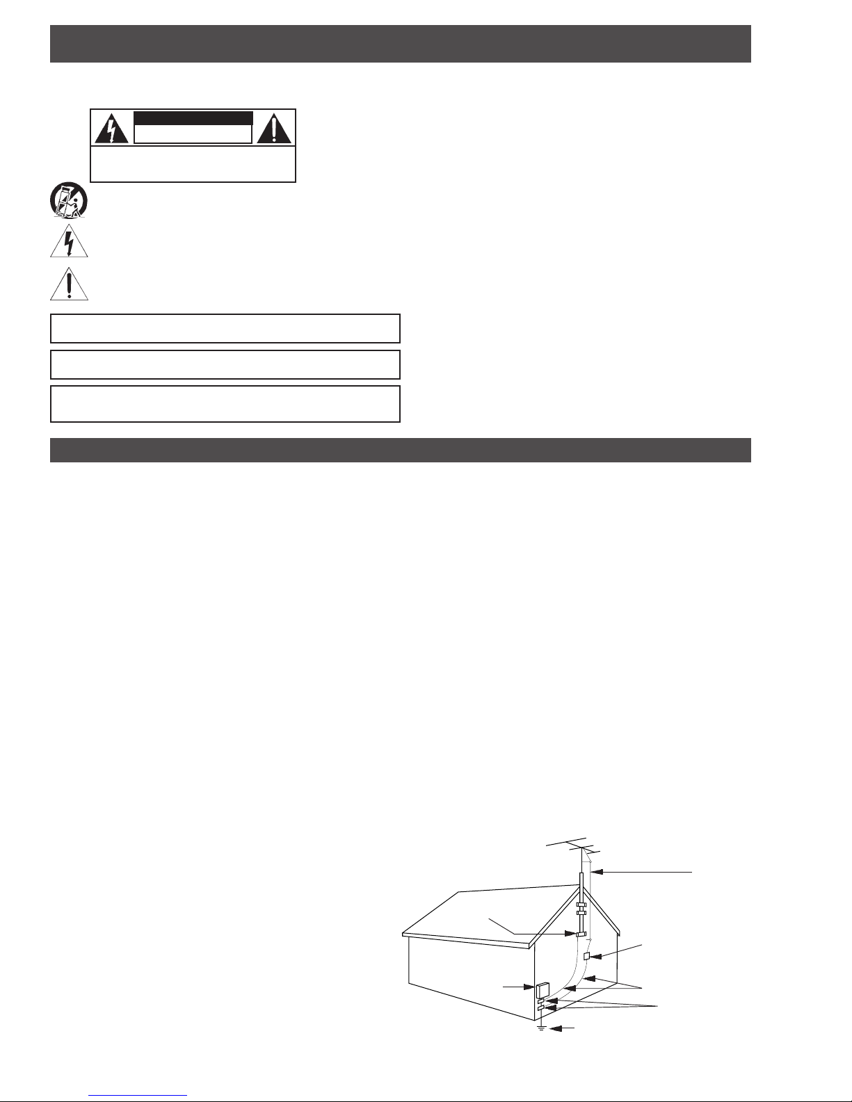
14. Outdoor Antenna Grounding—If an outside antenna or cable system is connected to the
product, be sure the antenna or cable system is grounded so as to provide some protection against
voltage surges and built-up static charges. Article 810 of the National Electrical Code, ANSI/NFPA
70, provides information with regard to proper grounding of the mast and supporting structure,
grounding of the lead-in wire to an antenna discharge unit, size of grounding conductors, location
of antenna-discharge unit, connection to grounding electrodes, and requirements for the
grounding electrode. See Figure A.
15. Lightning—For added protection for this product during a lightning storm, or when it is left
unattended and unused for long periods of time, unplug it from the wall outlet and disconnect the
antenna or cable system. This will prevent damage to the product due to lightning and power-line
surges.
16. Power Lines—An outside antenna system should not be located in the vicinity of overhead
power lines, other electric light or power circuits, where it can fall into such power lines or circuits.
17. Overloading—Do not overload wall outlets, extension cords, or integral convenience
receptacles as this can result in a risk of fire or electric shock.
18. Object and Liquid Entry—Never push objects of any kind into this product through openings
as they may touch dangerous voltage points or short-out parts that could result in a fire or electric
shock. Never spill liquid of any kind on the product.
19. Servicing—Do not attempt to service this product yourself as opening or removing covers may
expose you to dangerous voltage or other hazards. Refer all servicing to qualified service
personnel.
20. Damage Requiring Service—Unplug this product from the wall outlet and refer servicing to
qualified service personnel under the following conditions:
a. When the power-supply cord or plug is damaged,
b. If liquid has been spilled, or objects have fallen into the product,
c. If the product has been exposed to rain or water,
d. If the product does not operate normally by following the operating instructions. Adjust only
those controls that are covered by the operating instructions as an improper adjustment of other
controls may result in damage and will often require extensive work by a qualified technician to
restore the product to its normal operation,
e. If the product has been dropped or damaged in any way, and
f. When the product exhibits a distinct change in performance—this indicates a need for service.
21. Replacement Parts—When replacement parts are required, be sure the service technician
has used replacement parts specified by the manufacturer or have the same characteristics as
the original part. Unauthorized substitutes may result in fire, electric shock or other hazards.
22. Safety Check—Upon completion of any service or repairs to this product, ask the service
technician to perform safety checks to determine that the product is in proper operating condition.
23. Wall or Ceiling Mounting—The product should be mounted to a wall or ceiling only as
recommended by the manufacturer.
24. Heat—The product should be situated away from heat sources such as radiators, heat
registers, stoves, or other products (including amplifiers) that produce heat.
NOTE TO CATV SYSTEM INSTALLERS:
THIS REMINDER IS PROVIDED TO CALL THE CATV SYSTEM INSTALLER'S ATTENTION TO
ARTICLE 820 - 40 OF THE NEC THAT PROVIDES GUIDELINES FOR PROPER GROUNDING
AND, IN PARTICULAR, SPECIFIES THAT THE CABLE GROUND SHALL BE CONNECTED TO
THE GROUNDING SYSTEM OF THE BUILDING, AS CLOSE TO THE POINT OF CABLE ENTRY
AS PRACTICAL.
EXAMPLE OF ANTENNA GROUNDING
ANTENNA
LEAD IN
WIRE
GROUND CLAMP
ELECTRIC
SERVICE
EQUIPMENT
POWER SERVICE GROUNDING ELECTRODE
SYSTEM (NEC ART 250, PART H)
ANTENNA
DISCHARGE UNIT
(NEC SECTION 810-20)
GROUNDING
CONDUCTORS
(NEC SECTION 810-21)
GROUND CLAMPS
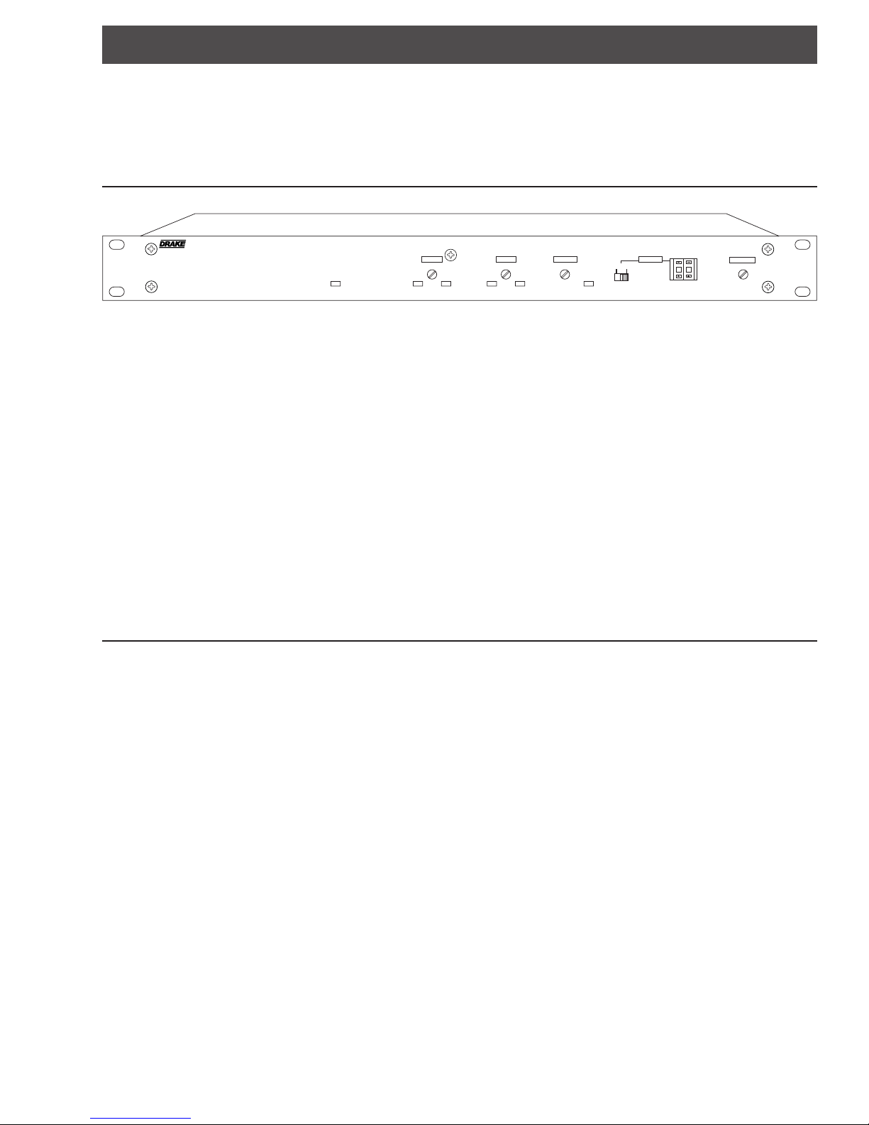
Table of Contents / Description / Specifications 3
TABLE OF CONTENTS
2 Caution Statements
2 Important Safety Instructions
3 Table of Contents / Description / Specifications
4 Front Panel Controls and Indicators
5 Rear Panel Controls and Connections
VIDEO
POWER
LEVEL
NORMAL
6 Installation / Installation Diagram
7 Channel Assignments
9 Internal Jumper Settings
10 Service / If You Need To Call For Help
11 Warranty
OVER-MOD
NORMAL
AUDIO
LEVEL
OVER-MOD
A / V RATIO
EAS ACTIVE
CHANNEL
CATV
CATV +
100
VM2860 VIDEO MODULATOR
25
RF OUTPUT
DESCRIPTION
The R.L Drake VM2860 and VM2862 Video Modulators are high
quality, vestigial sideband units with synthesized visual and aural
carriers. They are designed to accept NTSC video and audio
baseband signals from a satellite receiver or similar equipment.
Front panel video and audio level controls with accompanying
modulation indicators permit easy setup of the proper modulation
levels. The A/V ratio and RF output level controls are also provided
on the front panel. A rear panel EAS alternate IF input is also
provided. The VM2860 model is for applications with mono audio
and the VM2862 model provides BTSC stereo encoded audio. If
SAP is required, this option is available for the VM2862 model, and
is field installable.
Synthesized operation provides complete frequency agility, allowing
front panel selection of any standard CATV channel from 2 to 135
(54 to 862 MHz band). FCC required offsets for aeronautical
channels are automatically provided for each channel that requires
an offset. For special applications, IRC or HRC CATV frequencies
or off-air broadcast frequencies can be selected after moving an
internal jumper.
A high quality IF SAW filter with FCC predistortion eliminates
adjacent channel interference and provides optimum delay
characteristics.
SPECIFICATIONS - VM2860 / VM2862
Frequency Range:
FCC Offsets:
Output Level:
Amplitude Stability:
Output Impedance:
Frequency Stability:
Spurious Outputs:
Phase Noise:
Output Filter Bands:
Broadband Noise:
Input Impedance:
Frequency Response:
In-channel C/N:
Differential Gain:
Differential Phase:
MONO AUDIO
Input Impedance:
RF
A/V Ratio:
VIDEO
Input Level:
L/C Delay:
Input Level:
54 MHz to 864 MHz.
Standard CATV channels 2 to 135.
Broadcast, HRC, and IRC channel plans available by
internal jumper.
Automatic, positive.
+60 dBmV minimum, 12 dB minimum adjustment
range.
± 1 dB.
75 Ohms, 12 dB return loss within output filter
passband.
-12 dB to -25 dB.
± 5 ppm. All oscillators locked to the same internal
reference.
-60 dBc at +60 dBmV output level, 5 MHz to
1000 MHz, 15 dB A/V ratio.
-85 dBc at 10 kHz offset.
54 MHz to 258 MHz, 258 MHz to 462 MHz, 462 MHz
to 660 MHz, 660 MHz to 864 MHz.
-80 dBc, 4 MHz bandwidth, +60 dBmV output level,
±18 MHz offset within output filter passband, -90 dBc
outside of output filter passband, output filtered into 4
approximately 200 MHz wide bands.
1 Vp-p ± 3 dB, manual gain adjustment with
modulation indicators.
75 Ohms, 25 dB return loss.
20 Hz to 4.2 MHz, ± 1 dB with 4.5 MHz trap off,
20 Hz to 4.1 MHz, ±1 dB with 4.5 MHz trap on.
65 dB.
±50 nS of FCC predistortion with 4.5 MHz trap off,
-20 +80 nS of FCC predistortion with 4.5 MHz trap on.
± 3%.
0
± 3
.
250 mVrms to 2.5 Vrms, manual gain adjustment with
LED modulation indicators.
10K Ohms, unbalanced.
An auto-switching alternate IF input, labeled EAS input, is provided
for connection of an Emergency Alert System 44 MHz IF signal.
When the EAS IF signal appears at the EAS input, the main video
and audio modulated IF is replaced by the EAS input signal.
A 4.5 MHz video trap may be selected via an internal jumper
(VM2862 has 4.5 MHz trap on as factory setting). This may be used
to filter off a 4.5 MHz sound subcarrier or undesired video
components to prevent interference to the stereo or SAP channels.
The RF section of the modulator contains bandpass filtering that
divides the 54 to 862 MHz output range into four bands, each
approximately 200 MHz wide. This filtering, in conjunction with the
use of high level, low noise floor mixing, ensures very low
broadband noise at the output. Thus a full complement of up to all
134 available channels from VM2860 or VM2862 modulators may
be combined while maintaining an excellent C/N of each channel.
All of the mentioned features, combined with a carefully designed
low noise and low distortion output stage, provide reliable operation
in a densely crowded SMATV or CATV environment.
The inclusion of a fan in the VM2860 and VM2862 permits rack
mounting of this equipment without leaving the typical 1U air space
between modulators.
MONO AUDIO, cont'd.
Pre-emphasis:
Frequency Response :
BTSC STEREO AUDIO
Frequency Response:
Frequency Response:
Auto Switching Level:
Input Level:
Input Impedance:
Separation:
SAP AUDIO Option
Input Level:
Input Impedance:
EAS INPUT
Impedance:
Isolation:
GENERAL
AC Power:
Temperature Range:
Radiated Emissions:
75 µS.
50 Hz to 15 kHz, ±1 dB.
THD:
0.5% maximum.
S/N:
65 dB.
(VM2862 only)
250 mVrms to 2.5 Vrms, manual gain adjustment with
LED modulation indicators.
10K Ohms, unbalanced.
30 db, 50 Hz to 12.5 kHz; 25 dB, 12.5 kHz to 14 kHz.
± 0.5 dB, 50 Hz to 14 kHz.
THD:
0.5% maximum.
S/N:
65 dB.
(VM2862 only)
250 mVrms to 2.5 Vrms, manual gain adjustment with
over-modulation indicator.
10K Ohm, unbalanced.
±2 dB, 50 Hz to 10 kHz.
THD:
1% maximum.
S/N:
80 dB.
Level :
+30 dBmV, ±1 dB (visual carrier).
75 Ohm, 20 dB return loss.
60 dB.
+20 dBmV.
115 VAC ± 10%, 60 Hz,
23 Watts (VM2860), 28 Watts (VM2862).
Fuse:
1/2 Amp Slo-Blo 5 X 20 mm.
0° to 50° C.
Cooling:
Internal 1.85 CFM fan allows operation in the rack
without air spaces between units.
FCC Part 15.
Size:
11.25" D x 1.75" H x 19" W
Weight:
8 lbs. 8 oz.
4 Front Panel Controls and Indicators
F1
POWER
NORMAL
F2
VIDEO
LEVEL
F3
Figure 1 - FRONT PANEL
F1 - POWER Indicator
This LED lights when the unit is connected to a source of
AC power. The LED flashes when on an invalid channel or
if there is a synthesizer error.
F2 - VIDEO LEVEL Control
The setting of this screwdriver adjustment determines the
video modulation level. Clockwise rotation increases the
depth of modulation. After installing the unit, and with a
nominal 1 Vp-p video source connected, adjust the VIDEO
LEVEL control to a point where the red LED modulation
indicator (see item F3) just remains off (87.5% depth of
modulation). It is normal for the green modulation indicator
to be on with only sync level video input.
F3 - MODULATION Indicators (Video)
The green LED will be turned on continuously with sync
level or higher video input. An overmodulation condition is
noted with the red LED turned on continuously. The
VIDEO LEVEL control should be set to a point where the
red LED just remains off (see item F2).
F6 F7 F8 F9
A / V RATIO
EAS ACTIVE
CHANNEL
CATV
CATV +
100
VM2860 VIDEO MODULATOR
25
OVER-MOD
NORMAL
F4
AUDIO
LEVEL
OVER-MOD
F5
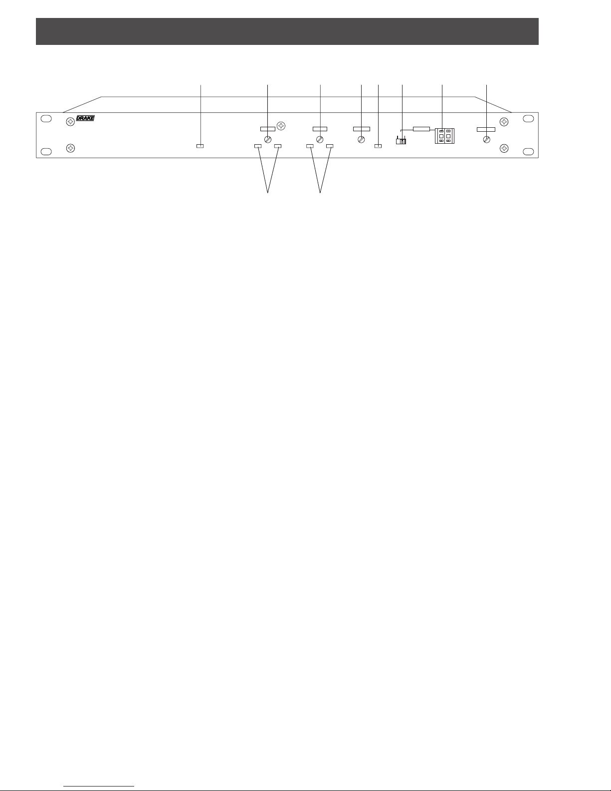
F6 - A/V RATIO Control
This screwdriver adjustment varies the level of the aural
carrier over a range from 12 to 25 dB below the visual
carrier. The aural carrier should be adjusted to
approximately 15 dB below the visual carrier (normal
operation). Clockwise rotation increases the aural carrier
level and thus decreases the A/V ratio.
F7 - EAS ACTIVE Indicator
This indicator lights when a signal is present at the EAS
input (R2) indicating that the modulator has switched to the
EAS signal.
F8 - CATV, CATV +100 CHANNEL Switch
This two position switch allows selection of the desired
operating channel from 02 to 99 (when the switch is in the
CATV position) and channels 100 to 135 (when the switch
is in the CATV +100 position). See the CHANNEL
ASSIGNMENTS section for a list of the corresponding
operating frequency, and offset, if any, for each channel
number.
F10
RF OUTPUT
F4 - AUDIO LEVEL Control
The setting of this screwdriver adjustment determines the
audio deviation level. Clockwise rotation increases the
level. After installing the unit and with the audio source
connected, adjust the AUDIO LEVEL control to a point
where the green LED is turned on continuously and the red
LED just remains off (25 kHz peak deviation).
F5 - MODULATION Indicators (Audio)
The green LED will be turned on continuously for peak
deviations of approximately 2.5 kHz (10% of 25 kHz
maximum) or greater. An overmodulation condition is
noted with the red LED turned on continuously. The
AUDIO LEVEL control should be set to a point where the
red LED just remains off (see item F4).
F9 - CHANNEL Switch
These pushwheel switches allow the selection of the
desired operating channel from 01 to 135. See the
CHANNEL ASSIGNMENTS section for a list of the
corresponding operating frequency, and offset, if any, for
each channel number.
F10 - RF OUTPUT LEVEL Control
This screwdriver adjustment varies the RF OUTPUT level.
Clockwise rotation increases the level.
 Loading...