

Page 1

VM2551A
AGILE COMMERCIAL VIDEO MODULATOR
( F o r U s e i n N T S C S y s t e m s )
I N S T R U C T I O N M A N U A L
VM2551A VIDEO MODULATOR
® is a registered trade mark of the R .L . Dra ke Holdings LLC
© Copyright 2013 R .L . Dra ke Holdings LL C P/N: P rinted in China.
651232400A
V001 12102013
1002412A/1002423A
Page 2

2 Caution Statements
WAR NING : T O P R E VE NT FIR E OR
E LE C TR IC AL S HOC K , DO NO T
E XP OS E T O R AIN OR MO IS TUR E
with care. Quick stops, excessive force and uneven
surfaces may cause the product and cart combination
to overturn.
The lightning ash with arrow head symbol, within an
equilateral triangle, is intended to alert the user to the
presence of uninsulated "dangerous voltage" within
the product's enclosure that may be of su fcient
magnitude to constitute a risk of electric shock to
persons.
The exclamation point within an equilateral triangle is
intended to alert the user to the presence of important
operating and maintenance (servicing) instructions in
the literature accompanying the product.
WAR NIN G : TO R E DUC E T H E R IS K OF F IR E O R E LE C TR IC S HOC K, DO NOT E XP OS E THIS P R O DUC T TO
R AIN O R MO IS TUR E .
DO NOT OP E N T HE C AB INE T, R EF E R S E RV IC ING T O QUAL IF IE D P E R S ON NE L O NLY.
CA UTI ON: TO P R E VE NT ELE C T R IC SHOC K, DO NOT U S E T H IS (P OLAR IZ E D) P LUG WIT H AN E XT E N S ION
C O RD R E CE PTAC LE O R O T HE R OUT L E T UN LE S S T H E B L ADE S C AN B E F ULLY INS E R TE D T O
P R E VE NT B LADE E XP OS UR E .
ATT E NTI ON: P OU R P R E VE NIR L E S C HO C S E LE C TR IQ UE S , NE PAS U T ILIS E R C ET T E F IC HE P O L AR IS E E
AVE C UN P ROLO NG AT E UR , UNE P R IS E DE C OU R AN T OU UNE AUT R E S OR TIE DE C OUR ANT,
S AUF S I L E S L AME S P E UVE NT ET R E INS E R E E S A FO ND S ANS E N LAIS S ER AUC U NE PAR TIE A
DE C OUVE R T.
A product and cart combination should be moved
Important S afet y Inst ruc tions :
1. Re ad Inst ruc tions : All the safety an d opera ting ins tructions should be read before the product is operated.
2. Ret ain Inst ruc tions : The safety and operating ins tructions should be retained for future reference.
3. He ed War ning s: All warnings on the product an d in the oper ating instructions should be adhere d to.
4. Follo w Inst ru ctio ns: All operating an d use ins tructions should be followed.
5. C leanin g: Unplug this produc t from the wa
6. Atta c hments : Do not use attachments that are not recommended by the product manufa cturer a s they may cause hazard s.
7. W ater and Mois ture: Do not us e this product nea r water—for e xample, nea r a bathtub, wash bowl, kitchen sink or laundry tub; in a wet bas ement;
or nea r a swimming pool; and the like.
8. Acces s ories : D o not place this product on an unstable cart, stand, tripod, bracket, or table. The product ma y fall, causing serious injury to a c hild
or adult, and serious damag e to the product. Us e only with a cart, stand, tripod, brack et, or table recommend
the product. Any mounting of the product s hould follow the manufa cturer's ins tructions, and shoul d us e a mounting accessor y recommende d by the
manufa cturer.
9. A product and cart combination s hould be moved with care. Quick stops, excessiv e force, and uneve n surface s may caus e the product and cart
combination to overturn.
10. Ven tilatio n: S lots and openings in the cabin et are provided for ventilation and to ensur e reliable opera tion of the product and to protect it from
overh
e ating, an d these openings must not be blocked or covered. The openings should neve r be blocked by placing the product on a bed, sofa, rug,
or similar surface. T his product s hould not be placed in a built-in ins talla tion such as bookcas e or rac k unless proper ventilation is provided or the
manufa cturer's ins tructions have been adhered to.
11. Po wer So urce s : T his product should be opera ted only from the type of power source indicated on the marking label. If you
of power supplied to your home, consult your product deale r or local power compa ny. F or products intended to oper ate from ba ttery power, or other
sources , re fer to the operating instructions.
12. Groundin g or Po lariza tion: T his product may be equipped with a polarized alternating-current line plug (a plug having one blade wider than the
other). T his plug will fit into the power outlet only one way. T his is a sa fety feature. If you are unab
the plug. If the plug s hould still fail to fit, contact your electrician to replac e your obsolete outlet. Do not defea t the sa f
plug. Alternate Warning s – If this product is equippe d with a three-wir e grounding- type plug, a plug havin g a third (grounding) pin, the plug will only fit
into a grounding-type power outlet. This is a s afety feature. If you are unable to inse rt the plug into the ou
obsolete outlet. D o not defeat the safety purpos e of the grounding-type plug.
ll outlet before cleaning. Do not us e liquid c leaners or aerosol c lean sers . Us e a damp c loth for cleanin g.
e d by the manufa ct
are not sur e of the type
le to inse rt the plug fully into the outlet, try reve rsing
ety purpose of the polarized
tlet, co ntact your electrician to repla ce your
Page 3

Caution Statements (continued)
Outdoor Antenna Grounding: If an outside antenna or cable system is connected to the product, be sure the antenna or cable system is
13.
grounded so as to provide some protection against voltage surges and built-up static charges. Article 810 of the National Electrical Code,
ANSI/NF PA 70, provides information with regard to proper grounding of the mast and supporting structure, grounding of the lead-in wire t o an
antenna discharge unit, size of grounding conductors, location of antenna-discharge unit, connection to grounding electrodes, a nd requirements for
the grounding electrode.
14. Power-C ord P ro tec tion: Power-s upply cords should be routed so that they ar e not likely to be walked on or pinched by items placed upon or aga inst
them, paying pa rticular attention to cords at plugs, convenience re ceptacles, and the point where they exit from the product.
15. Li ghtni ng: F or adde d protection for this product during a lightning storm, or when it is left unattended and unus ed for long periods of time, unplu
from the wall outlet and dis connect the antenna or cable sys tem. T his will prevent dama ge to the product due to lightning a nd power-line surges .
16. Power L ines : An outside antenna sys tem should not be located in the vicinity of overhea d power lines , other el ectric light or power c ircuits, where it
can fa ll into s uch power lines or circuits. When installing an outside a ntenna s ystem, extreme ca re should be taken to keep from touch
lines or circuits as contact with them may be fatal.
17. Ov erlo adin g: Do not overload wall outlets, extension cords, or integral convenience re ceptacles as this can result in a risk of fire or e lectric s hock.
18. Objec t and Liqu id E ntry : Ne ver push objec ts of a ny kind into this product through openings as they ma y touch dangero us voltage points or short-out
parts that could result in a fire or elec tric shock. Ne ver s pill liq
19. S ervic ing: Do not a ttempt to service this product yourse lf as opening or re moving covers ma y expo se you to dangerous voltage or other haz ards.
R efer all serv icing to qualified s ervice pers onnel.
20. Dama ge R equiring S erv ice: Unplug this product from the wa ll outlet and refer servicing to qualified s ervice pers onnel under the following conditions:
a) When the power-s upply cord or plu
b) If liquid has been spill ed, or objects have fallen into the product,
c) If the product has been expose d to ra in or water,
d) If the product doe s not opera te normally by following the operating instructions.
A djust only those controls that are covered by the operating instructions as a n improper adjustment of other controls may result in damage and will
often requi re extens ive work by a qualified technician to restore the pro
in a ny way, and f. W hen the product exhibits a distinct chan ge in performanc e—this indica tes a need for service.
21. R eplace m ent P art s: W hen replacement pa rts are require d, be sure the service technicia n has used replaceme nt parts specified by the ma nufac turer
or have the s ame chara cteristics as the original pa rt. Unauthorized s ubstitutes may res u
22. S afety C hec k: Upon completion of any service or repairs to this product, as k the service technicia n to perform safety checks to de termine that the
product is in proper opera ting condition.
23. Wall or Ce iling Mounting: T he product shou ld be mounted to a wall or ceiling only as recommend ed by the manufacturer.
24. Heat: T he product should be situated away from heat source s such as radiators, heat registers , stoves , or other pro
produce heat.
g is damag ed,
uid of any kind on the product.
duct to its normal operation, e. If the product has been dropped or damaged
lt in fire, electric shock or other hazar ds .
ducts (including amplifiers ) that
3
g it
ing such power
Page 4
4 Table of Contents / Description / Specications
TABLE OF CONTENTS
2 Caution Statements
2 Important Safety Instructions
4 Table of Contents / Description / Specications
5 Front / Rear Panel Controls and Indicators
6 Operation
7 Adjustments
8
Channel Assignments
10
Service / If You Need to Call For Help
11
Warra nty
VM2551A VIDEO MODULATOR
DESCRIPTION
The R.L. Drake VM2551A Agile Video Modulator is a high quality,
vestigial sideband unit with synthesized visual and aural carriers.
It is designed to accept NTSC video and audio baseband signals from
a satellite receiver or similar equipment. Front panel video and audio
level controls with accompanying modulation indicators permit easy
setup of the proper modulation levels. The A/V ratio and RF output level
controls are also provided on the front panel. A rear panel EAS alternate
IF input is also provided.
Synthesized operation provides complete frequency agility, allowing
front panel selection of any standard CATV channel from 2 to 78. FCCrequired osets for aeronautical channels are automatically provided for
each channel that requires an oset. For special applications, IRC or HRC
CATV frequencies or o-air broadcast frequencies can be selected from
the front panel.
A high quality IF SAW lter with FCC pre-distortion eliminates adjacent
channel interference and provides optimum delay characteristics.
SPECIFICATIONS
VIDEO INPUT
Connector: F-Type (Female)
Impedance: 75 ohms
Return Loss: 18 dB
Video Input Level: 0.7 volt Peak-to-Peak
Signal-to-Noise Rao: 58 dB
Differenal Gain: 2.0%
Differenal Phase: 1.0 degree
Over-modulaon Indicator: 87 to 92%
L/C Delay: Per FCC Requirements
RF OUTPUT
Connector: F-Type (Female)
Impedance: 75 ohms
Return Loss: 12 dB
Channel Modes: CATV (STD, IRC, HRC), UHF, VHF
Power Level Range: +50 to +60 dBmV (in 0.2 dB increments)
Video Flatness: fv-0.5 to fv+4.2 MHz: 1.5 dB p/v
Carrier-to-Noise: -63 dB
Broadband Noise: -77 dBc
Spurious Outputs: -63 dBc
Aural/Visual Carrier Rao: -15 ± 5 dB
GENERAL
AC Power: 117 VAC ± 10%, 60 Hz, 23 Wa max
Fuse: 0.4A Type T 250 V
Temperature Range: 32° to 122° F
Size: 19.0” W x 14.25” D x 1.75” H
Weight: 7 lbs.
A manual or auto-s witching alternate IF input, la beled EAS input,
is provided for connection of an Emergency Alert System 44 MHz
IF signal. When the EAS IF signal appears at the EAS input, the
main video and audio modulated IF is replaced by the EAS input
signal.
The EAS/Alternate IF feature allows a choice between manual
and automatic selection of the EAS/ALT IF input signal. This
is done through a 3 position terminal strip on the rear of the unit.
In the manual mode the EAS/ALT IF feature is activated by a contact
closure switch, which completes a ground connection. In the
automatic mode, two positions on the terminal strip are jumpered
together enabling an automatic detection circuit in the unit. When an
EAS/ALT IF signal is routed to the EAS/ALT port the unit automatically
switches to that alternate signal.
MONO AUDIO
Connector: RCA-Type
Input Impedance: Greater than 10k ohms, unbalanced
Input Level: 0.5 to 4.0 volt Peak-to-Peak
Frequency Range: 50 Hz to 15 kHz
Frequency Response: ± 0.5 dB
Total Harmonic Distoron: 1% @ 25 kHz deviaon
Signal-to-Noise Raon: 59 dB
Over-modulaon Threshold: 25 ± 2 kHz peak deviaon
IF
Input/Output Connector: F-Type (Female)
Aural Frequency: 41.25 MHz
Visual Frequency: 45.75 MHz
COMPOSITE IF
Aural: +20 dBmV
Visual: +35 dBmV
Input/Output Impedance: 75 ohms
Input/Output Return Loss: 16/15 dB
EAS / ALTERNATIVE IF
Connector: F-Type (Female)
Input Level: +30 dBmV @ 45.75 MHz
Switch Isolaon: Greater than 60 dB
Page 5

Front and Rear Panel Controls and Indicators 5
Opera Controls
All opera
[11]
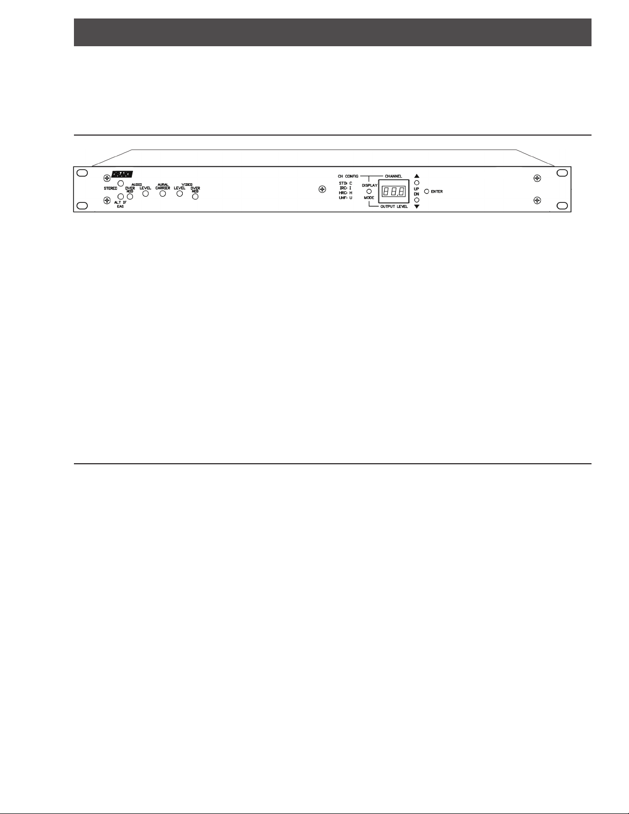
[1] EAS/ALT INDICATOR: Lights Red when EAS/ALT is ac ve.
[2] VIDEO OVERMODULATION LED: Lights when modula
[3] VIDEO MODULATION LEVEL: Adjusts percentage of modula
[4] AURAL-TO-VISUAL CARRIER RATIO: Controls amplitude of aural RF carrier rela
[5] AUDIO MODULATION LEVEL: Adjusts aural carrier modula
[6] AUDIO OVERMODULATION LED: Lights when peak devia
[7] DISPLAY MODE BUTTON: Used to scroll through channel configura
[8] CHANNEL, CHANNEL CONFIGURATION/OUTPUT LEVEL DISPLAY
[9] UP/DOWN BUTTONS:
[10] ENTER BUTTON:
[11] STEREO INDICATOR:
controls and indicators for the modulator are located on, or are accessible from the front panel.
[1]
[6] [5] [4] [3] [2]
[7] [8]
is above 87.5%.
.
.
of aural carrier is over 25 kHz.
output level and modes.
Used to scroll through the channel, channel conguration and output level modes.
Not used.
[10]
VM2551A VIDEO MODULATOR
[9]
Figure 1 - Front Panel
ve to visual RF carrier.
Note: All c to the unit are made at the rear panel.
[5]
[3]
[4]
[8]
[1]
[2]
[1] RF OUTPUT: + 60 dBmV
[2] IF INPUT: +35 dBmV IF Input
[3] EAS/ALT IF INPUT: Emergency Alert or Alternate IF Input
[4] IF OUT: +35 dBmV IF Output (See note #8 below)
[5] EAS/ALT IF TERMINAL:
EAS / ALT IF mode selection (see page 7)
[6] AUDIO INPUT: Audio input (standard)
[7] VIDEO INPUT: 1 Volt PP video input
[8] IF LOOP CABLE: The IF loop cable (supplied) must be installed to provide RF connuity. The
not have an RF output without the IF loop installed.
[6]
Figure 2 - Rear Panel
modulator will
[7]
Page 6

Operation6
Opera n
VM2551A Channel Display in STD configuraon Mode.
Display Mode
This bu
The res
Channel
The output channel is selected by pressing the UP or DN bu on when in the channel display mode.
The LED display will blink indica
The actual channel is not changed un
If the ENTER bu
Pressing and holding the UP or DN bu
All internal a
on scrolls through the selec of Channel, Channel Configura Output Level mode in this order.
g state (default) of the modulator’s display mode is the channel number.
g a transi state.
the ENTER bu on is pressed.
on is not pressed, the display will return to res g state a er 30 seconds.
on will allow for faster scrolling of channel.
enuators are temporarily set for maximum a enua during channel change (output is muted).
and
Channel Configura
The Channel Configura is changed by pressing the UP or DN bu on when in the Channel Configura display mode.
The LED display will blink indica
The channel configura
If the ENTER bu
If the mode is to be changed and it is not a valid mode for the exis
mode will be selected, and the channel will default to channel-2.
The available Channel Configura
C = Standard (default from factory)
I = IRC
H = HRC
U = Broadcast VHF/UHF
Error
The Display will show a flashing "EE1" if the PLL1 is not locked.
The Display will show a flashing "EE2" if the PLL2 is not locked.
The Display will show a flashing "EE3" if both PLL1 and PLL2 are not locked.
All internal a
Please contact our Service Department should any of these errors condi
on is not pressed, the display will return to res g state a er 30 seconds.
enuators are automa cally set for maximum a enua in any of the above condi (output is muted).
is not changed un the ENTER bu on is pressed.
g a transi state.
g channel, when the ENTER bu on is pressed, the new
are as follows:
occur.
Page 7

Adjustments
ADJUSTMENTS
VIDEO LEVEL: With the intended signal source connected and a representave video program
present, turn the VIDEO LEVEL ADJUST control clockwise unl the Video Overmod-
ulaon light just flashes, then back off slightly. Alternavely, while watching the
picture on a good TV monitor, adjust the control to the highest (clockwise) level
that does NOT cause the highlights (white porons of the picture) to become
“washed out”.
AUDIO LEVEL: Turn the AUDIO LEVEL ADJUST control clockwise unl the Audio Overmodulaon
light just flashes slightly on the loudest peaks of the audio program material.
OUTPUT LEVEL: The OUTPUT LEVEL is adjusted by pressing the UP or DN buons when in the
OUTPUT LEVEL display mode. The LED display will blink indicang a transion
state. The output level is not changed unl the ENTER buon is pressed. If the
ENTER buon is NOT pressed, the display will return to its resng state aer 30
seconds. Pressing and holding the UP or DN buon will allow for faster scrolling.
The level increments in 0.2 dB steps. Output level accuracy is typically +/- 1 dB of
display, +/- 2 dB worst case.
7
A/V CARRIER RATIO: To adjust the aural-to-visual carrier rao, tune the RF indicator device to the aural
carrier frequency and adjust the AURAL CARRIER control to obtain the desired
aural carrier level. Recommended rao is -15 dB.
EAS / ALT IF
AUTOMATIC: Connect a jumper to the terminal strip auto posion. EAS will switch on when a
+30 dBmV EAS IF signal is detected.
MANUAL: EAS is acve with a ground connecon on the manual posion of the terminal
strip.
Page 8

8
HR C
EIA CH# /
Ou tput C hanne l
S witc h S etting
Visual Carrier
F requ ency (MH z)
S TD IRC
Channel Assignments s
01
02
03
04
05
06
07
08
09
10
11
12
13
14
15
16
17
18
19
20
21
22
23
24
25
26
27
28
29
30
31
32
33
34
35
36
37
38
39
40
41
42
43
44
45
46
47
48
49
50
51
52
53
54
55
56
57
58
59
60
61
62
63
64
65
66
67
68
69
70
71
72
73
74
75
76
77
78
N/A
55. 25
61. 25
67. 25
77. 25
83. 25
175.25
181.25
187.25
193.25
199.25
205.25
211.25
121.2625
127.2625
133.2625
139.25
145.25
151.25
157.25
163.25
169.25
217.25
223.2625
229.2625
235.2625
241.2625
247.2625
253.2625
259.2625
265.2625
271.2625
277.2625
283.2625
289.2625
295.2625
301.2625
307.2625
313.2625
319.2625
325.2625
331.275
337.2625
343.2625
349.2625
355.2625
361.2625
367.2625
373.2625
379.2625
385.2625
391.2625
397.2625
403.25
409.25
415.25
421.25
427.25
433.25
439.25
445.25
451.25
457.25
463.25
469.25
475.25
481.25
487.25
493.25
499.25
505.25
511.25
517.25
523.25
529.25
535.25
541.25
547.25
73. 25
79. 25
85. 25
72. 00
54. 00
60. 00
66. 00
78. 00
84. 00
174.00
180.00
186.00
192.00
198.00
204.00
210.00
120.00
126.00
132.00
138.00
144.00
150.00
156.00
162.00
168.00
216.00
222.00
228.00
234.00
240.00
246.00
252.00
258.00
264.00
270.00
276.00
282.00
288.00
294.00
300.00
306.00
312.00
318.00
324.00
330.00
336.00
342.00
348.00
354.00
360.00
366.00
372.00
378.00
384.00
390.00
396.00
402.00
408.00
414.00
420.00
426.00
432.00
438.00
444.00
450.00
456.00
462.00
468.00
474.00
480.00
486.00
492.00
498.00
504.00
510.00
516.00
522.00
528.00
534.00
540.00
546.00
TAB L E 1:
C AT V
Sub Band Channels
Channel Standard Video
T7
T8
T9
T10
T11
T12
T13
T14
7
13
19
25
31
37
43
49
Page 9

Channel Assignments (continued) 9
Visual Carrier
F requ ency (MHz )
C han ne l Number
Visual Carrier
F requ ency (MHz )
C han ne l Number
TABLE 2: BROADCAST TV CHANNELS
VHF BROADCAST CHANNELS
UHF BROADCAST CHANNELS
2
3
4
5
6
7
8
9
10
11
12
13
55. 25
61. 25
67. 25
77. 25
83. 25
175.25
181.25
187.25
193.25
199.25
205.25
211.25
14
15
16
17
18
19
20
21
22
23
24
25
26
27
471.25
477.25
483.24
489.25
495.25
501.25
507.25
513.25
519.25
525.25
531.25
537.25
543.25
549.25
Page 10

10 Service / If You Need to Call For Help
SERVICE INFORMATION
A Return Material Authorizaon (RMA) Number is required on ALL PRODUCT RETURNS (regardless of whether the product is being returned for repair or for credit). Product that is received at the factory without an RMA Number will be returned to the Sender, unopened.
RMA Numbers must be used when returning product for credit or repair. Use of RMA Numbers will ensure efficient processing. When
needing to return your product to R.L. Drake Holdings, LLC., please follow these simple steps listed below (in the order that they appear).
SERVICE REPAIRS ONLY CREDIT RETURNS ONLY
1. Contact R.L. Drake Holdings, LLC.’s Service Department 1. Contact R.L. Drake Holdings, LLC.’s Service Department
in one of three ways: in one of three ways:
A. Phone: 937-746-6990 A. Phone: 937-746-6990
B. Email: servicehelp@rldrake.com B. Email: servicehelp@rldrake.com
C. Fax: 937-806-1510 C. Fax: 937-806-1510
2. Request from Drake Service a copy of the Product Return 2. Request from Drake Service a copy of the Product Return
Authorizaon Form. Authorizaon Form.
3. Complete the Product Return Authorizaon Form fully. 3. Complete the Product Return Authorizaon Form fully.
4. Return the completed Product Return Authorizaon Form 4. Return the completed Product Return Authorizaon Form
to the Drake Service Department using one of the contact to the Drake Service Department using one of the contact
methods listed in Step 1. methods listed in Step 1.
5. Aer compleng Steps 1 through 4, an RMA Number will 5. Aer compleng Steps 1 through 4, an RMA Number will
be assigned to you. be assigned to you.
6. Securely pack the product and mark the box with your RMA 6. Securely pack the product in its original undamaged box
Number. If shipping mulple boxes, all boxes must be mark- (returning the product without its original packaging in good,
ed with the RMA Number. Place the RMA Number near the new condion may cause the incursion of addional fees).
return address in large, bold print (approx. 2” in height). Pack this box within another shipping container or box.
Mark the shipping box or container with your RMA Number.
Place the RMA Number near the return address in large,
bold print (approx. 2” in height).
7. Ship your “SERVICE REPAIR ONLY” return to: 7. Ship your “CREDIT RETURNS ONLY” return to:
R.L. Drake Holdings, LLC.
Attn: Product Service Returns
710 Pleasant Valley Drive
Springboro, OH 45066
*NOTE: All Credit Returns are subject to a 15% Restock Fee
**NOTE: All shipments are to be PRE-PAID by the sender. NO COD’s will be accepted.
IF YOU NEED TECHNICAL HELP
Call our Customer Service/Technical Support line at +1 (937) 746-6990 between 8:00 A.M. and 4:00 P.M. Eastern Standard Time, weekdays.
Please have the unit’s serial number available. We will also need to know the specifics of any other equipment connected to the unit. When
calling, please have the unit up and running, near the phone if possible. Our technician(s) will likely ask certain quesons to aid in diagnosis
of the problem. Also, have a voltmeter handy, if at all possible.
R.L. Drake Holdings, LLC.
An: Product Credit Returns
One Jake Brown Road
Old Bridge, NJ 08857
DRAKE also provides technical assistance by Email: servicehelp@rldrake.com
Fax: (937) 806-1510.
Many of the products that are sent to us for repair are in perfect working order when we receive them. For these units, there is a standard
checkout fee that will be charged. Please perform whatever steps are applicable from the product’s Instrucon Manual before calling or
wring - this could save unnecessary phone charges. Please do not return the product without calling Drake Service and following the steps
above first; it is preferred to help troubleshoot the problem over the phone (or by Email) first, saving you both me and money.
Page 11

Warranty 11
Warranty
3 YEAR LIMITED WARRANTY
Seller will at its sole opon, either repair or replace (with a new or factory recondioned product, as Seller may determine) any product manufactured or sold
(or in the case of soware, licensed) by Seller which is defecve in materials or workmanship or fails to meet the applicable specificaons that are in effect on
the date of shipment or such other specificaons as may have been expressly agreed upon in wring: (i) for a period of three (3) years from the date of original
purchase for all stock hardware products (other than those specifically referenced herein below having a shorter warranty period); (ii) for a period of one (1)
year from the date of original purchase, with respect to all MegaPort™, IPTV products, test equipment and fiber opcs receivers, transmiers, couplers and integrated receiver/distribuon amplifiers; (iii) for a period of one (1) year from the date of original purchase (or such shorter period of me as may be set forth
in the license agreement specific to the parcular soware being licensed from Seller) with respect to all soware products licensed from Seller (other than
Core Product Soware) that is (a) developed for a specific funcon or applicaon, (b) complimentary to and does not funcon without the Core Product Soware, and (c) listed with a specific model number and stock number in Seller’s Price List (“Non-Core Soware”); (iv) for a period of ninety (90) days from the
date of original purchase, with respect to non-serialized products and accessories, such as parts, sub-assemblies, spliers, and all other products sold by Seller
(other than Core Product Soware and Refurbished/Closeout Products) not otherwise referred to in clauses (i) through (iii) above. The warranty period for
computer programs in machine-readable form included in a hardware product, which are essenal for the funconality thereof as specifically stated in the
published product specificaons (“Core Product Soware”) will be coincident with the warranty period of the applicable hardware product within which such
Core Product Soware is installed.
Soware patches, bug fixes, updates or workarounds do not extend the original warranty period of any Core Product Soware or Non-Core Soware.
Notwithstanding anything herein to the contrary,
(i) Seller’s sole obligaon for soware that when properly installed and used does not substanally conform to the published specificaons in effect when the
soware is first shipped by Seller, is to use commercially reasonable efforts to correct any reproducible material non-conformity (as determined by Seller in its
sole discreon) by providing the customer with: (a) telephone or e-mail access to report non-conformance so that Seller can verify reproducibility, (b) a soware patch or bug fix, if available or a workaround to bypass the issue if available, and (c) where applicable, replacement or damaged or defecve external
media, such as CD-ROM disk, on which the soware was originally delivered;
(ii) Seller does not warrant that the use of any soware will be uninterrupted, error-free, free of security vulnerabilies or that the soware will meet the customer’s parcular requirements; and the customer’s sole and exclusive remedy for breach of this warranty is, at Seller’s opon, to receive (a) suitably modified
soware, or part thereof, or (b) comparable replacement soware or part thereof;
(iii) Seller retains all right, tle and interest in and to and ownership of all soware (including all Core Product Soware and Non-Core Soware) including any
and all enhancements, modificaons and updates to the same; and
(iv) in some cases, the warranty on certain proprietary sub-assembly modules manufactured by third-party vendors and contained in Seller’s products, third
party soware installed in certain of Seller’s products, and on certain private–label products manufactured by third-pares for resale by Seller, will be of shorter duraon or otherwise more limited than the standard Seller limited warranty. In such cases, Seller’s warranty with respect to such third-party proprietary
sub-assembly modules, third-party soware and private-label products will be limited to the duraon and other terms of such third-party vendor’s warranty,
if any. In addion, certain products, that are not manufactured by Seller, but are resold by Seller, may carry the original OEM warranty for such products, if any.
The limited warranty set forth above does not apply to any product sold by Seller, which at the me of sale constuted a Refurbished/Closeout Product, the limited warranty for which is provided in the following paragraph.
Seller will at its sole opon, either repair or replace (with a new or factory-recondioned product, as Seller may determine) any product sold by Seller which at
the me of sale constuted a refurbished or closeout item (“Refurbished/Closeout Product”), which is defecve in materials or workmanship or fails to meet
the applicable specificaons that are in effect on the date of shipment of that product or fails to meet such other specificaons as may have been expressly agreed upon in wring between the pares, for a period of ninety (90) days from the date of original purchase. Notwithstanding the foregoing, in some cases the
warranty on certain proprietary sub-assembly modules manufactured by third-party vendors and contained in Seller products, third party soware installed in
certain of Seller’s products, and on certain private–label products manufactured by third-pares for resale by Seller will be of shorter duraon or otherwise
more limited than Seller limited warranty for Refurbished/Closeout Products. In such cases, Seller’s warranty for Refurbished/Closeout Products constung
such third party proprietary sub-assembly modules, third party soware, and private-label products will be limited to the duraon and other terms of such
third-party vendor’s warranty, if any. In addion, notwithstanding the foregoing, (i) certain Refurbished/Closeout Products that are not manufactured (but are
resold) by Seller, may carry the original OEM warranty for such products, if any, which may be longer or shorter than Seller’s limited warranty for Refurbished/
Closeout Products. All sales of Refurbished/Closeout Products are final.
To obtain service under this warranty, the defecve product, together with a copy of the sales receipt, serial number if applicable, or other sasfactory proof of
purchase and a brief descripon of the defect, must be shipped freight prepaid to Seller at the following address: One Jake Brown Road, Old Bridge, NJ 08857.
This warranty does not cover failure of performance or damage resulng from (i) use or installaon other than in strict accordance with manufacturer’s wrien
instrucons, (ii) disassembly or repair by someone other than the manufacturer or a manufacturer-authorized repair center, (iii) misuse, misapplicaon or abuse, (iv) alteraon, (v) exposure to unusual physical or electrical stress, abuse or accident or forces or exposure beyond normal use within specified operaonal
or environmental parameters set forth in applicable product specificaons, (vi) lack of reasonable care or (vii) wind, ice, snow, rain, lightning, or any other weather condions or acts of God.
OTHER THAN THE WARRANTIES SET FORTH ABOVE, SELLER MAKES NO OTHER WARRANTIES OR REPRESENTATIONS OF ANY KIND, EXPRESS OR IMPLIED, AS TO THE CONDITION, DESCRIPTION, FITNESS FOR A PARTICULAR PURPOSE, MERCHANTABILITY, OR AS TO ANY OTHER MATTER, AND SUCH WARRANTIES SET FORTH ABOVE SUPERSEDE ANY ORAL OR WRITTEN
WARRANTIES OR REPRESENTATIONS MADE OR IMPLIED BY SELLER OR BY ANY OF SELLER’S EMPLOYEES OR REPRESENTATIVES, OR IN ANY OF SELLER’S BROCHURES MANUALS, CATALOGS, LITERATURE OR OTHER MATERIALS. IN ALL CASES, BUYER’S SOLE AND EXCLUSIVE REMEDY AND SELLER’S SOLE OBLIGATION FOR ANY BREACH OF THE WARRANTIES CONTAINED
HEREIN SHALL BE LIMITED TO THE REPAIR OR REPLACEMENT OF THE DEFECTIVE PRODUCT F.O.B. SHIPPING POINT, AS SELLER IN ITS SOLE DISCRETION SHALL DETERMINE. SELLER
SHALL IN NO EVENT AND UNDER NO CIRCUMSTANCES BE LIABLE OR RESPONSIBLE FOR ANY CONSEQUENTIAL, INDIRECT, INCIDENTAL, PUNITIVE, DIRECT OR SPECIAL DAMAGES BASED
UPON BREACH OF WARRANTY, BREACH OF CONTRACT, NEGLIGENCE, STRICT TORT LIABILITY OR OTHERWISE OR ANY OTHER LEGAL THEORY, ARISING DIRECTLY OR INDIRECTLY FROM
THE SALE, USE, INSTALLATION OR FAILURE OF ANY PRODUCT ACQUIRED BY BUYER FROM SELLER.
All claims for shortages, defects, and non-conforming goods must be made by the customer in wring within five (5) days of receipt of merchandise, which writing shall state with parcularity all material facts concerning the claim then known to the customer. Upon any such claim, the customer shall hold the goods
complained of intact and duly protected, for a period of up to sixty (60) days. Upon the request of Seller, the customer shall ship such allegedly nonconforming
or defecve goods, freight prepaid to Seller for examinaon by Seller’s inspecon department and verificaon of the defect. Seller, at its opon, will either repair, replace or issue a credit for products determined to be defecve. Seller’s liability and responsibility for defecve products is specifically limited to the defecve item or to credit towards the original billing. All such replacements by Seller shall be made free of charge f.o.b. the delivery point called for in the original order. Products for which replacement has been made under the provisions of this clause shall become the property of Seller. Under no circumstances are
products to be returned to Seller without Seller’s prior wrien authorizaon. Seller reserves the right to scrap any unauthorized returns on a no-credit basis.
Any acons for breach of a contract of sale between Seller and a customer must be commenced by the customer within thirteen (13) months aer the cause of
acon has accrued. A copy of Seller’s standard terms and condions of sale, including the limited warranty, is available from Seller upon request. Copies of the
limited warranes covering third-party proprietary sub-assembly modules and private-label products manufactured by third-pares may also be available from
Seller on request. (Rev 0713)
Page 12

R.L. Drake Holdings, LLC
710 Pleasant Valley Drive
Springboro, OH 45066
(937) 746-4556
www.rldrake.com
 Loading...