

Page 1
®
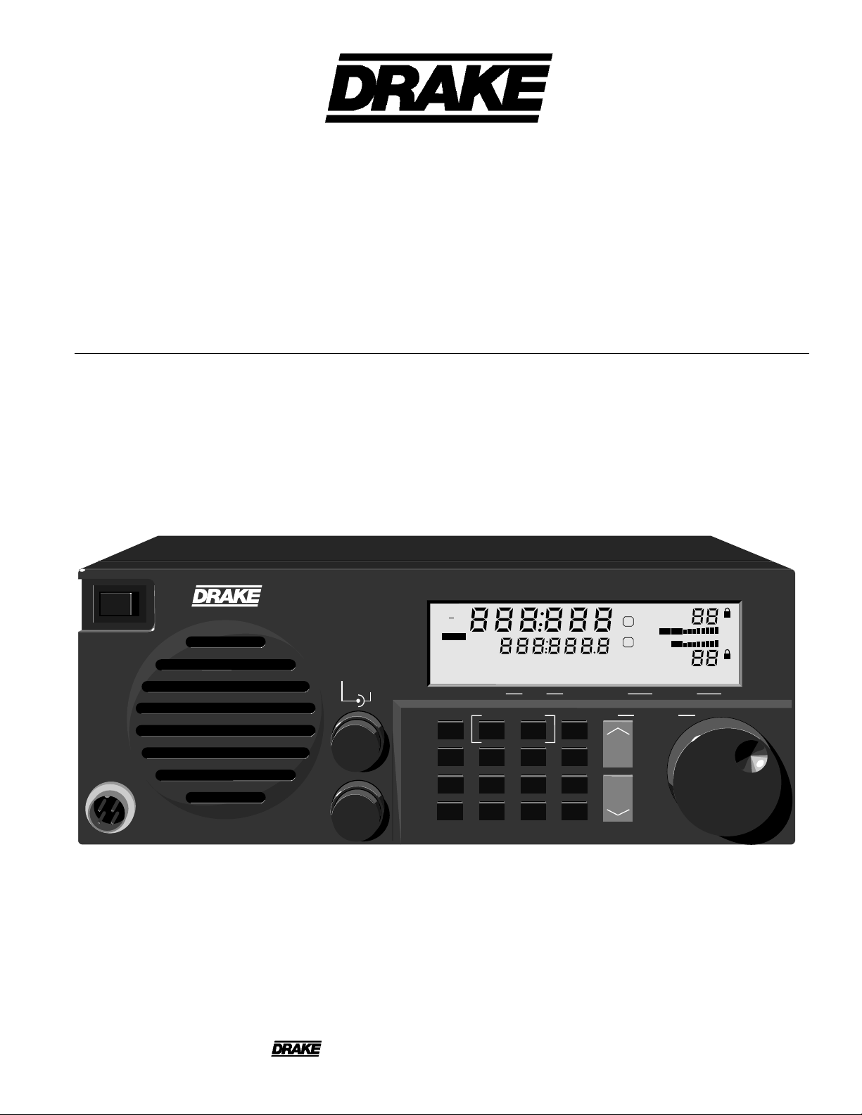
TR270 FM Transceiver
Owner's Manual
POWER
MIC
TR270 FM Transceiver
VOLUME
SQUELCH
A
B
REV
+
NUM
TEMP
SCAN
DEC
DTMF
ENC
TOT
PRIO
RPT
DTMF
NUM
HOLD TO SCAN
5
89
0
LOCK
123
4
7
*
SAT
DATA
WXSAT
VOICE
A MODE B
MEM
VFO
6
REV
SAT
B BW
CTS
#
STORE
VOICE
DATA
A
A / B
B
MODE
C
P. OUT
D
SETUP
W
N
LOCKED
SETUP
LMH
VFO 1
VFO 2
A
B
VFO 1
VFO 2
DCDCONMAIL
XMT
TNC STATUS
TUNING
PW
MEM
TX
RX
RX
PW
MEM
STA
is a registered trademark of the R. L. Drake Company
®
© Copyright 1997 R. L. Drake Company P/N: 3851400A-5-1997 Printed in the U. S. A.
Page 2

WARNING: TO PREVENT FIRE OR
ELECTRICAL SHOCK DO NOT
EXPOSE TO RAIN OR MOISTURE
¡WARNING!
RISK OF ELECTRIC SHOCK
DO NOT OPEN
WARNING: TO REDUCE THE RISK OF ELECTRIC
SHOCK,
DO NOT REMOVE COVER
NO USER-SERVICABLE PARTS INSIDE
REFER SERVICING TO QUALIFIED PERSONNEL
Important Safeguards i
An appliance and cart combination should be moved
with care. Quick stops, excessive force and uneven
surfaces may cause the appliance and cart combination to overturn.
The lightning flash with arrow head symbol, within an
equilateral triangle, is intended to alert the user to the
presence of uninsulated "dangerous voltage" within
the product's enclosure that may be of sufficient
magnitude to constitute a risk of electric shock to
persons.
The exclamation point within an equilateral triangle is
intended to alert the user to the presence of important operating and maintenance (servicing) instructions in the literature accompanying the appliance.
WARNING:
TO REDUCE THE RISK OF FIRE OR ELECTRIC SHOCK, DO NOT EXPOSE THIS APPLIANCE
TO RAIN OR MOISTURE.
DO NOT OPEN THE CABINET, REFER SERVICING TO QUALIFIED PERSONNEL ONLY.
CAUTION:
TO PREVENT ELECTRIC SHOCK, DO NOT USE THE THREE WIRE CORD WITH AN EXTENSION
CORD RECEPTACLE OR OTHER OUTLET UNLESS THE BLADES CAN BE FULLY INSERTED TO
PREVENT BLADE EXPOSURE.
ATTENTION:
POUR PREVENIR LES CHOCS ELECTRIQUES, NE PAS UTILISER CETTE FICHE POLARISEE
AVEC UN PROLONGATEUR, UNE PRISE DE COURANT OU UNE AUTRE SORTIE DE COURANT, SAUF SI LES LAMES PEUVENT ETRE INSEREES A FOND SANS EN LAISSER AUCUNE
PARTIE A DECOUVERT.
1. Read Instructions—All the safety and operating instructions should be
read before the appliance is operated.
2. Retain Instructions—The safety and operating instructions should be
retained for future reference.
3. Heed Warnings—All warnings on the appliance should be adhered to.
4. Follow Instructions—All operating and use instructions should be
followed.
5. Cleaning—Unplug this appliance from the wall outlet before cleaning.
Do not use liquid cleaners or aerosol cleansers. Use a damp cloth for
cleaning.
6. Do Not Use Attachments—not recommended by the manufacturer or
they may cause hazards.
7. Water and Moisture—Do not use this product near water—for example,
near a bathtub, wash bowl, kitchen sink, laundry tub, in a wet basement,
or near a swimming pool—and the like.
8. Accessories—Do not place this product on an unstable cart, stand,
tripod, bracket, or table. The product may fall, causing serious injury to a
child or adult, and serious damage to the appliance.
9. Ventilation—This product should never be placed near or over a
radiator or heat register. This product should not be placed in a built-in
installation such as a bookcase or rack unless proper ventilation is provided
or the manufacturer’s instructions have been adhered to. Any slots or
openings in the cabinet are provided for ventilation. To ensure reliable
operation of the video product and to protect it from overheating, these
openings must not be blocked or covered. The openings should never be
blocked by placing the product on a bed, sofa, rug, or other similar surface.
10. Grounding or Polarization—This product is equipped with a 3- wire
line cord receptacle. It is intended for use with a 3-wire properly grounded
power socket. Do not defeat the safety purpose of the supplied line cord
and plug.
10A. Mise à la terre ou Polarisation—Cet appareil est équipé avec un
cordon d'alimentation à trois fils. Il est a brancher sur une prise ayant un
connecteur a la terre. Assurez-vous que la connection a la terre ne manque
pas.
11. Power Sources—This product should be operated only from the type
of power source indicated on the marking label. If you are not sure of the
type of power supplied to your home, consult your appliance dealer or local
power company.
12. Power-cord Protection—Power-supply cords should be routed so
they are not likely to be walked on or pinched by items placed upon or
against them. Pay particular attention to cords at plugs, convenience
receptacles, and the point where they exit from the appliance.
13. Lightning—For added protection for this product during a lightning
storm, or when it is left unattended and unused for long periods of time,
unplug it from the wall outlet.
14. Power Lines—An outside antenna system should not be located in the
vicinity of overhead power lines, other electric light or power circuits, where
it can fall into such power lines or circuits. When installing an outside
antenna system, extreme care should be taken to keep from touching such
power lines or circuits as contact with them may be fatal.
Page 3
ii Important Safeguards, continued
15. Overloading—Do not overload wall outlets and extension cords as this
can result in a risk of fire or electric shock.
16. Object and Liquid Entry—Never push objects of any kind into this
product through openings as they may touch dangerous voltage points or
short-out parts that could result in a fire or electric shock. Never spill liquid
of any kind on the product.
17. Servicing—Do not attempt to service this product yourself as opening
or removing covers may expose you to dangerous voltage or other
hazards. Refer all servicing to qualified service personnel.
18. Damage Requiring Service—Unplug this product from the wall outlet
and refer servicing to qualified service personnel under the following
conditions:
a. When the power-supply cord or plug is damaged.
b. If liquid has been spilled, or objects have fallen into the product.
c. If the product has been exposed to rain or water.
d. If the product does not operate normally by following the operating
instructions. Adjust only those controls that are covered by the operating
instructions. An improper adjustment may result in damage and will often
require extensive work by a qualified technician to restore the product to its
normal operation.
e. If the product has been dropped or the cabinet has been damaged.
f. When the product exhibits a distinct change in performance—this
indicates a need for service.
19. Replacement Parts—When replacement parts are required, be sure
the service technician has used replacement parts specified by the
manufacturer or have the same characteristics as the original parts.
Unauthorized substitutes may result in fire, electric shock or other hazards.
20. Safety Check—Upon completion of any service or repairs to this
product, ask the service technician to perform safety checks to determine
that the product is in proper operating condition.
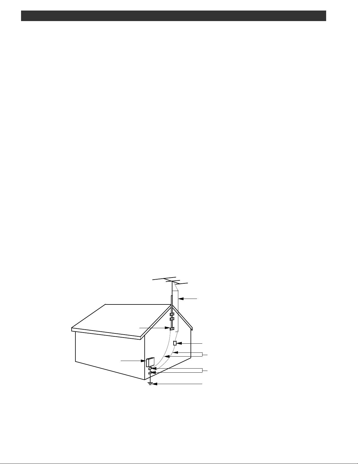
21. Outdoor Antenna Grounding—Before attempting to install this product, be sure the antenna or cable system is grounded so as to provide some
protection against voltage surges and built-up static charges.
a. Use No.10 AWG (5.3mm
No.17 AWG (1.0mm
2
) copper, No.8 AWG (8.4mm2) aluminum,
2
) copper-clad steel or bronze wire or larger, as ground
wire.
b. Secure antenna lead-in and ground wires to house with stand-off
insulators spaced from 4 feet (1.22m) to 6 feet (1.83m) apart.
c. Mount antenna discharge unit as close as possible to where lead-in
enters house.
d. A driven rod may be used as the grounding electrode where other types
of electrode systems do not exist. Refer to the National Electrical Code,
ANSI/NFPA 70-1990for information.
e. Use jumper wire not smaller than No.6 AWG 13.3mm
2
) copper or
equivalent, when a separate antenna grounding electrode is used.
"EFFECTUER LE CABLAGE CONFORMEMENT AU CODE CANADIEN DE L' ELECTRICITE"
" INSTALL WIRING ACCORDING TO THE CANADIAN ELECTRICAL CODE"
ΕΞΑΜΠΛΕ ΟΦ ΑΝΤΕΝΝΑ ΓΡΟΥΝ∆ΙΝΓ
ΑΝΤΕΝΝΑ
ΛΕΑ∆ ΙΝ
ΩΙΡΕ
ΓΡΟΥΝ∆ ΧΛΑΜΠ
ΑΝΤΕΝΝΑ
∆ΙΣΧΗΑΡΓΕ ΥΝΙΤ
(ΝΕΧ ΣΕΧΤΙΟΝ 810−20)
ΕΛΕΧΤΡΙΧ
ΣΕΡςΙΧΕ
ΕΘΥΙΠΜΕΝΤ
ΝΕΧ − ΝΑΤΙΟΝΑΛ ΕΛΕΧΤΡΙΧ ΧΟ∆Ε
ΓΡΟΥΝ∆ΙΝΓ ΧΟΝ∆ΥΧΤΟΡΣ
(ΝΕΧ ΣΕΧΤΙΟΝ 810−21)
ΓΡΟΥΝ∆ ΧΛΑΜΠΣ
ΠΟΩΕΡ ΣΕΡςΙΧΕ ΓΡΟΥΝ∆ΙΝΓ
ΕΛΕΧΤΡΟ∆Ε ΣΨΣΤΕΜ
(ΝΕΧ ΑΡΤ 250, ΠΑΡΤ Η)
Page 4

Table of Contents iii
Thank you for purchasing a Drake TR270 FM Transceiver.
This transceiver has been designed and manufactured
to high quality standards, and will provide reliable
operation for many years.
Important Safeguards
Table of Contents
Specifications and Accessories
Introduction
General Description
Safety / Voltage Selection
Installation
Unpacking
Location
Fixed Installation
Portable / DC Power Installation
Antenna Requirements
Installation Diagram
Front Panel Description
Microphone Connector Wiring Sense
i
iii
iv
1
1
2
4
4
4
4
4
4
5
6
7
Please carefully read the Owner's Manual in order to
take advantage of the many interesting features that
will provide enjoyable radio operation.
Voice Operation
FM Simplex Operation
Repeater Operation
Standard Offsets
Custom Offsets
Subaudible Tone Operation
DTMF Operation
To store A Phone Number
To Transmit A Stored Phone Number
Inband Repeat Operation
Crossband Repeat Operation
Satellite Operation
Introduction To Satellite Operation
The Amateur Satellites-Modes and
Frequencies
Doppler Frequency Shift Correction
FM voice Operation With A Satellite
9600 Baud Packet Operation
With A Satellite
27
27
27
27
27
28
28
29
29
29
30
31
31
33
33
33
34
Front Panel Display
Rear Panel Description
Getting Started
Beep Tones
Getting Started (Initial Settings)
Dual VFO's
Direct Frequency Entry
Setup Menu
Restore Factory Setup Settings
Memory Functions
Memory Channel Programming
Recalling A Memory Channel
Changing Memory Channel
Construct A Memeory List
Locking A Memory Channel
Restore Factory Memory
Programming
Scan Functions
Scan Memory
Scan VFO
Locking A Memory Channel
8
10
12
12
12
13
13
14
14
20
20
20
20
20
21
21
22
23
25
26
Computer Control
Computer Interface With The
RS-232C Port
Command Set
To Save A Report
Data / FAX Operation
Data Operation With The Optional
TNC 270 (Terminal Node Controller)
Fax Operation With The Optional
DEMOD270
Suggested References
Glossary of Terms
Quick Reference Guide
Service
Warranty
FCC Warning
The user is cautioned that changes or modifications
not expressly approved by the R. L. Drake company could void the user's authority to operate the
equipment.
NOTE: In order for an installation of this product to
maintain compliance with the limits for a Class B
device, shielded cables must be used.
37
38
38
40
41
41
41
42
43
45
52
53
Page 5

iv Specifications and Accessories
RECEIVER 'A' (2M only)
Receive Frequency Range:
IF Frequencies:
Sensitivity:
Selectivity:
Adjacent Channel Rejection:
IMD (in band) and Spurious Responses:
144.00 - 148.00 MHz (142 - 150 MHz reduced specifications)*
1st IF: 10.7 MHz
2nd IF: 455 kHz
<0.18 µV, 12dB SINAD (144 - 148 MHz)
12 kHz min. @ -6 dB
-75 dB min. @ ± 20 kHz
-80 dB min. @ ± 25 kHz
-80 dB min.
Squelch Sensitivity:
Image Rejection:
Audio Power Output:
TRANSMITTER
Transmit Frequency Range:
Transmit Power Output:
Modulation Mode:
Deviation, max.:
Spurious Emissions:
Microphone Impedance:
Antenna 2 Preamp Power:
Packet Data Rate:
Antenna Impedance:
Memory Channels:
Tuning Steps:
/ Frequency Stability:
IF Rejection:
Protection:
GENERAL
<0.10 µV
-80 dB min.
-80 dB min.
2W into 8 Ohms @ less than 5% distortion.
144.00 - 148.00 MHz (142 - 150 MHz reduced specifications)*
1/10/25 Watts (144 to 148 MHz)
16KF3E Frequency Modulation.
5 kHz peak.
-60 dBc (-80 dBc in-band).
500 Ohms.
Overtemperature and high VSWR.
13.6 VDC nominal @ 100 mA
1200/9600 bps (G3RUH compatible)
50 Ohms
400 total: 100 (00-99) each receiver, A and B.
100 SAT mode
100 WXSAT mode
5, 10, 12.5, 15, 20, 25 kHz, 1 MHz ( / buttons only).
±5ppm (0
±10ppm (-100C to +500C)
0C
to +400C)
Current Requirement, receive:
Current Requirement, transmit:
ACCESSORIES FOR THE TR270:
TNC270 module
DEMOD270 module
Carrying handle
Voltage Requirement:
Operating Temperature:
Case Size:
Weight:
RECEIVER 'B' (wide coverage)
Receive Frequency Range:
IF Frequencies:
Sensitivity:
Selectivity:
Adjacent Channel Rejection:
IMD: (in-band):
IF Rejection:
Image Rejection:
*142 - 150 MHz operation with proof of MARS or CAP license.
115 or 230 VAC ± 10%, 50/60 Hz, 75 Watts or
11 - 16 VDC, negative Ground.
13.6 VDC @ 1.2A, nominal.
13.6 VDC @ 8A max. (high power RF output).
-100C to +500C ambient.
Width 11", Height 4-3/4", Depth 13-1/2"
13 lbs. (5.9 Kg.)
136 - 174 MHz and 420 - 470 MHz
1st IF: 18 MHz
2nd IF: 455 kHz
0.25µV/12 dB SINAD
15 kHz or 40 kHz @ -6 dB, selectable.
-60 dB min. @ ± 25 kHz, N BW
-75 dB min. @ ± 50 kHz, W BW or N BW
-75 dB min.
75 dB min.
60 dB min.
Page 6

Introduction - General Description 1
MIC
TUNING
B
A MODE B
A
SQUELCH
123
4
5
6
89
7
0
REV
SAT
B BW
LOCK
STORE
CTS
RPT
DTMF
PRIO
VFO
MEM
#
A / B
A
MODE
B
P. OUT
C
SETUP
D
NUM
*
VOLUME
HOLD TO SCAN
TNC STATUS
LMH
NUM
TEMP
SCAN
DTMF
TOT
DEC
ENC
DATA
VOICE
SAT
WXSAT
DATA
VOICE
LOCKED
SETUP
W
N
XMT
DCDCONMAIL
REV
+
TX
STA
VFO 1
VFO 2
PW
MEM
RX
RX
VFO 1
VFO 2
PW
MEM
A
B
TR270 FM Transceiver
POWER
DESCRIPTION
The TR270 is a table-top, base station, amateur radio 2
Meter FM Transceiver plus an additional extended range
FM receiver. Microprocessor control and synthesized
tuning permit full transceive capability on transmitter/
receiver ‘A’ from 144 to 148 MHz*, while receiver ‘B’
permits independent reception in the extended range
of: 136 - 174 MHz, and 420 - 470 MHz. Transceiver ‘A’ is
capable of 25 Watts RF output, with output power easily
programmable from the front panel keypad for high,
medium and low power output levels. Receiver ‘B’ is
operational regardless of the receive/transmit status of
transceiver ‘A’. Independent Volume and Squelch
controls are provided for both the ‘A’ and ‘B’ receivers.
Control of either ‘A’ or ‘B’ is via the front panel keypad
and frequency tuning is accomplished by the Tuning
wheel,
/ buttons, or by direct entry for the
selected transceiver/receiver. Either receiver is capable
of carrier detect or time scanning. Scanning can be by
frequency limits or a memory scan. The TR270 has 400
programmable memory locations that are allocated as
follows: 100 memories for Transceiver ‘A’, 100 memories
for Receiver ‘B’, plus 100 additional memories assigned
to ‘WXSAT’, and 100 memories for the ‘SAT’ (satellite)
mode of operation. Both transceiver ‘A’ and receiver
‘B’ can operate simultaneously.
The front panel liquid crystal display provides visual
feedback to the operator of the current status of the
transceiver/receiver. Programming of the transceiver/
receiver's parameters is easily accomplished by the front
panel display and setup menu. Parameters are adjusted and set by using the tuning wheel and keypad.
*142 - 150 MHz operation with proof of MARS or CAP license.
The unit permits DTMF and CTCSS tone encoding/
decoding of transceiver ‘A’. A hand held microphone
with push-to-talk feature is included with the TR270.
DTMF functions can be initiated from the TR270 front
panel keypad. Both receivers permit subaudible tone
decoding and/or subaudible tone filtering.
In addition to normal voice FM communication, the
TR270 provides interfaces for both an internal packet
TNC and an external packet TNC. The optional, internal,
plug-in Drake TNC270 permits more efficient setup and
improved operation than an external TNC allows, since
the compatible setup commands/protocols are designed into the TR270 for the internal TNC. The packet
interfaces provide for 1200 bps or G3RUH compatible
9600 bps operation. Either receiver ‘A’ or ‘B’ can be
switched to either TNC interface. An RS-232C port is
provided for PC control of the TR270 and TNC270. PC
software is provided with the DRAKE® TNC270 option.
The optional, DRAKE® DEMOD270, AM/FM, demodulator
card, can also be installed to receive weather fax
(WEFAX) data, ACARS (In Flight Aircraft Reporting
Service) data, or HF FAX data. Weather satellite (WXSAT)
reception in the 137 MHz band is also provided by the
TR270 with the DEMOD270 installed. S-Band weather
satellite reception is possible with the addition of an
external downconverter prior to the TR270 with
DEMOD270 combination. ACARS reception requires a
receiver with aircraft band coverage. HF FAX reception
requires a receiver with HF band SSB coverage. The
demodulated audio data stream is supplied to the
TR270 RS-232C Interface connector. PC software is
provided with the Drake DEMOD270 option.
Page 7

2 Introduction - Safety / Voltage Selection
WARNING
NOTE: THE FOLLOWING PROCEDURE REQUIRES REMOVAL OF AN
EQUIPMENT COVER THAT EXPOSES POTENTIALLY LETHAL VOLTAGES IF
THE EQUIPMENT IS POWERED FROM AN AC POWER SOURCE. REFER
NOTE: A magnetized screwdriver facilitates the removal
and installation of screws in the procedure that follows:
SERVICING TO A QUALIFIED TECHNICIAN ONLY.
A) DISCONNECT THE TRANSCEIVER FROM ITS SOURCE OF
AC POWER.
B) Remove the top cover from the transceiver by
removing (6) Black screws, #6-32 x 1/4" PAN PHL. Retain
the cover and screws for later reassembly.
115 OR 230 VAC
SET INTERNALLY
FACTORY SET : 115 V
FUSE
LINE
3 A,250 V
115 V
SLO - BLO
T 1.6 A,250 V
+13.6 V
50
A N T E N N A 2
RECEIVE ONLY
VHF/UHF
+13.6VDC @100 mA
SWITCHED
CAUTION:
- RISK OF FIRE REPLACE FUSE AS
MARKED AFTER
DISCONNECTING UNIT
FROM AC LINE.
E X T S P K R
8
50
A N T E N N A 1
RECEIVE : VHF/UHF
TRANSMIT : 144 - 148 MHz
25 WATTS
MADE IN U.S.A.
R
BY
ATTENTION:
- RISQUE D'INCENDIE REMPLACEZ FUSIBLE DU
TYPE INDIQUE APRES
DEBRANCHER DU SECTEUR.
I N T E R F A C E
R S - 2 3 2 C
F A X /
D E M O D
INPUT
E X T E R N A L
T N C
D C I N P U T
+
13.6 VDC 6A
+
@
GND
230 V
50/60 Hz
75 WATTS
FUSE
C) Locate the power supply cover. Remove the cover
by removing (2) Screws, #4-40 x 1/4" PAN PHL Zinc from
the left-hand side of the unit and by removing (2) Nuts,
Hex #M3 x 6mm from the right-hand side of the compartment cover. Remove the cover by carefully releasing it
from the exposed studs at the right-hand side of the
cover. Retain the cover, screws, and nuts for later
reassembly.
(2) 1/4" screws
(2) hex nuts
(metric)
Power Supply
Cover
Page 8

Introduction - Safety / Voltage Selection, continued 3
WARNING!!!
Please read before applying power
The transceiver is normally shipped for operation on 115
VAC, 50/60 Hz AC input line voltage. If your operating
voltage is different than this, please refer to FIGURE 1 on
this page. An internal jumper permits changing the
allowable AC input voltage to a nominal 230 VAC. In
addition, the rear panel accessible mains fuse must
change accordingly. Please be certain of the operating
voltage before connecting the transceiver to the mains
source.
_________________________________________________________________
Note: The warranty does not cover damage as a result of
improper voltage selection, or replacement of the fuse
with ratings other than those specified.
_________________________________________________________________
WARNING
NOTE: THE FOLLOWING PROCEDURE REQUIRES REMOVAL OF AN
EQUIPMENT COVER THAT EXPOSES POTENTIALLY LETHAL VOLTAGES IF
THE EQUIPMENT IS POWERED FROM AN AC POWER SOURCE. REFER
SERVICING TO A QUALIFIED TECHNICIAN ONLY.
D) Ensure that the jumper is set for either the 115 VAC or
the 230 VAC position as required for the AC Mains
supply. Install the proper fuse at the rear panel of the
TR270.
CAUTION
In accordance with international safety standards,
this instrument is equipped with a three-wire power
cable receptacle. The unit is shipped with a detachable type three-wire power cable intended for nominal 115 VAC mains supply. When connected to an
appropriate power line outlet, this cable grounds the
instrument cabinet. For operation of this unit on
nominal 230 VAC mains supply, use the proper
power cable assembly approved by your local codes.
For use of this product outside the U. S. A. or Canada
on supply voltages of 220 VAC or greater, the discharge resistor (4.7 Meg Ohm) connected from the
neutral wire terminal of the AC input receptacle to the
receiver chassis must be removed.
115 VAC
JUMPER
(factory
setting)
Fuse: 3A, 250V (5x20mm) SLO-BLO
(factory installed)
JUMPER
FIGURE 1 - AC Mains
Voltage Selection
230 VAC
Fuse: T1.6A, 250V (5x20mm)
E) Reinstall the power supply compartment cover by
using the cover, screws, and nuts removed in step C.
F) Reinstall the transceiver top cover using the (6) Black
#6-32 x 1/4" screws PAN PHL that were removed in step B.
Page 9

4 Installation
UNPACKING
Carefully remove the transceiver from the shipping carton
and examine it for evidence of damage. If any damage
is noted, immediately contact the transportation company responsible for delivery or return the unit to the dealer
from whom it was purchased. Keep the shipping carton
and all packing material for the transportation company
to inspect. The original carton and packing material
should be retained for repackaging should it be necessary
to return the unit. Inspect the packing material for any
accessories or printed material before storing the box.
Locate the registration card, fill out, and immediately
return to the R. L. Drake Company to insure registration and
validation of warranty.
LOCATION
The location of the transceiver is not critical so long as
adequate clearance is provided to allow air circulation
in and around the unit, especially adjacent to the rear
panel mounted heatsink. To prevent overheating, do
not cover any ventilation slots in the top cover.
Side View of Transceiver
FIGURE 2 HEAT SINK
Heat Sink
PORTABLE/DC POWER INSTALLATION
For use in a portable environment, the transceiver
includes an unfused external DC input connector. This
connector is located on the rear panel. The transceiver
will operate with a DC input voltage of 11-16 VDC. Full
high power RF output during transmit is insured with a
nominal supply voltage of 13.6 VDC or higher, as are
supplied by typical automotive systems. The transceiver
may be powered from the vehicle’s cigarette lighter
socket. An approved method is to make fused wire
connections at the vehicle battery. Connect DC power
observing correct polarity and fusing (10 A Fast Blow
maximum) to avoid possible vehicle wiring damage
and/or fire. Connect the antenna(s) to the appropriate
antenna input(s) using 50 Ohm coax between the
antenna and the transceiver.
ANTENNA REQUIREMENTS
The receiver incorporates internal switching to allow two
separate antenna systems to be connected simultaneously. The unit will transmit out the ANTENNA 1
connector only, so a resonant 2-meter antenna must be
connected to ANTENNA 1. A separate single-band or
multiple-band antenna can also be connected to the
ANTENNA 2 connector. By simple setup programming,
either of the connected antennas can be split to either
receiver ‘A’ or ‘B’ for the receive mode. Additional
setup programming permits dedicated antenna usage
or automatic antenna selection by corresponding band,
VHF/UHF, or by frequency range. The typical antennas
for use with this transceiver will include Verticals, Beam,
or Ground Plane types with 50 Ohm coaxial cable feeds.
The best antenna will depend upon the desired frequency coverage and the intended communication link
distance.
FIXED INSTALLATION
After unpacking the unit and checking that the intended AC line voltage matches the internally set range
(factory set for 115 VAC) and corresponding fuse is
installed, connect the antenna system to the appropriate antenna input(s). Connect AC cord to mains
voltage. Connect any other external equipment at this
time. Refer to Figure 3 for the diagram of a typical fixed
installation.
Page 10

Installation, continued 5
VERTICALS, BEAM, GROUND PLANE
+13.6 V
50
A N T E N N A 2
RECEIVE ONLY
VHF/UHF
+13.6VDC @100 mA
SWITCHED
CAUTION:
- RISK OF FIRE REPLACE FUSE AS
MARKED AFTER
DISCONNECTING UNIT
FROM AC LINE.
E X T S P K R
8
- OR - - OR -
50 OHM COAXIAL
CABLE
PL-259
50
A N T E N N A 1
RECEIVE : VHF/UHF
TRANSMIT : 144 - 148 MHz
25 WATTS
MADE IN U.S.A.
BY
ATTENTION:
- RISQUE D'INCENDIE REMPLACEZ FUSIBLE DU
TYPE INDIQUE APRES
DEBRANCHER DU SECTEUR.
R
MAX.
I N T E R F A C E
R S - 2 3 2 C
F A X /
D E M O D
INPUT
E X T E R N A L
T N C
D C I N P U T
+
13.6 VDC 6A
+
GND
ATTENTION: LOCATE ANY
RECEIVER ANTENNAS SOME
DISTANCE AWAY FROM
TRANSMITTER ANTENNAS TO
AVOID POSSIBLE DAMAGE TO
THE RECEIVER.
115 OR 230 VAC
SET INTERNALLY
FACTORY SET : 115 V
FUSE
LINE
3 A,250 V
115 V
SLO - BLO
T 1.6 A,250 V
230 V
FUSE
50/60 Hz
75 WATTS
@
EXTERNAL
SPEAKER
TERMINAL
OR PC
TO EXTERNAL
TNC UNIT
FROM SW8, R8 SERIES RECEIVER
LINE AUDIO OUT FOR CW, RTTY,
HF FAX, WE FAX RECEPTION
(with optional Drake DEMOD270)
Standard 12 VDC Power Plug (fused)
(or approved accessory connector)
Vehicle
12 VDC
accessory
---------- ---------
---
--
--
connection
Fuse 10 A (Fast Blow)
FIGURE 3 INSTALLATION DIAGRAM
EXTERNAL DC
CONNECTOR
(supplied)
AC POWER
CORD
CONNECTION
Page 11

6 Front Panel Description
8 1 2
TR270 FM Transceiver
REV
+
NUM
POWER
VOLUME
SQUELCH
A
MIC
B
TEMP
SCAN
DEC
DTMF
ENC
TOT
PRIO
RPT
DTMF
NUM
HOLD TO SCAN
5
89
0
LOCK
123
4
7
*
SAT
DATA
WXSAT
VOICE
A MODE B
MEM
VFO
6
REV
SAT
B BW
CTS
#
STORE
VOICE
DATA
A
B
C
D
A / B
MODE
P. OUT
SETUP
W
N
LOCKED
SETUP
LMH
VFO 1
VFO 2
A
B
VFO 1
VFO 2
DCDCONMAIL
XMT
TNC STATUS
TUNING
PW
MEM
TX
RX
RX
PW
MEM
STA
6 7 5 4 3
FIGURE 4 FRONT PANEL
1) POWER ON/OFF Switch - This switch turns the transceiver on or off. When the unit is off, the display will be
blank. AC power is interrupted to the unit with the
switch in the off position.
2) Display - The backlit, liquid-crystal display provides
the current status of both receiver ‘A’ and ‘B’, such as
operating frequency, received signal strength, relative
transmit power, memory number, scan mode, simplex/
duplex operation with repeater offset sense, TNC
modes/setups, etc. Refer to FRONT PANEL DISPLAY, in
this manual, for a full description.
3) TUNING (VFO) - The tuning wheel and the
/
buttons are the primary tuning controls of the transceiver. Clockwise rotation of the tuning wheel increases frequency and counterclockwise rotation
decreases frequency. The tuning wheel also incorporates two-speed tuning. Rotating the tuning wheel
faster results in an increased tuning speed. The transceiver also accepts direct numeric frequency entry
from the numeric keypad buttons, see Item 4.
The / buttons also function to permit setting
parameters in certain programming operations. The
/ buttons are the only auto-repeating buttons.
TUNING WHEEL STEPS
The transceiver can be programmed to tune in different resolutions (steps) with the corresponding display
readout, as follows:
Transceiver ‘A’: 5, 10, 15, 20, and 25 kHz steps.
Receiver ‘B’: 5, 10, 12.5, 15, 20, and 25 kHz steps.
/ BUTTON STEPS
The button increases and the button decreases the frequency by fixed 1 MHz steps with each
depression of the button.
In the setup mode, the tuning wheel and the
/
buttons permit scrolling and selection of various trans-
ceiver parameters. The tuning wheel and
/
buttons are also used to scroll through memory channels in the memory mode of operation.
Page 12
Front Panel Description, continued 7
4
RPT
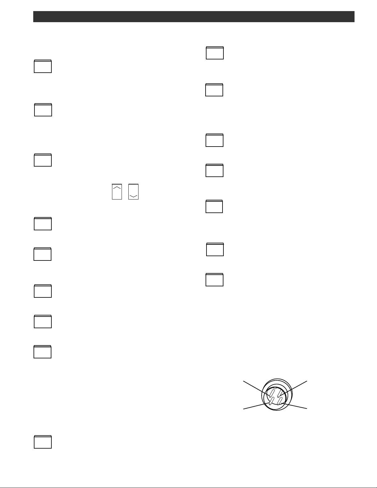
4) Program Buttons -
1
- Press once to switch the selected transceiver/
PRIO
receiver frequency to the programmed priority channel
frequency. Press and hold for approximately 2 seconds
to initiate the priority watch mode.
2
- Press once to put the selected transceiver/
VFO
receiver in the VFO tuning mode. For the selected
transceiver/receiver, press this button to toggle between VFO1 and VFO2. Also, press and hold this button
to initiate a VFO scan.
3
- Press once to recall the current memory
MEM
channel for the selected transceiver/receiver. Select
memory channel by direct numeric entry or scroll
through with tuning wheel or / buttons. Press
- Press for a second function keyshift. When
*
NUM
pressed, the orange button functions are active,
(i.e. 0-9, *, #, A, B, C, D).
0
- In the MEMORY mode, press this button to
LOCK
lockout the displayed memory channel during a
memory scan. Otherwise, press and hold this button to
lock/unlock all front panel buttons and tuning wheel
entries.
#
- Press to store selected entries when
STORE
programming.
A
- Press this button to alternately direct the
A / B
tuning and other keypad operations to the ‘A’ transceiver or ‘B’ receiver.
and hold to initiate MEMORY channel scan.
- Press to manually select the repeater offset
direction or simplex.
5
- With the repeater status displayed, press this
REV
button to reverse the repeater input/output frequency
format.
6
- Press to automatically configure the trans-
SAT
ceiver for the satellite communication mode.
7
- Press to select a programmed phone number
DTMF
for dialing. Up to 10 phone numbers can be stored.
8
For Transceiver ‘A’ - Press once to display the
CTS
current CTCSS tone frequency. Press a second, third
and fourth time before the display times out or within
approximately 3 seconds to select ‘ENC’, ‘DEC/ENC’,
or no tone on transmit or receive as required. The
selected state will remain operational after the display
times out.
For Receiver ‘B’ - Press once to display the
current CTCSS tone frequency. Press a second and
third time to enable or disable ('OFF') the tone decoding as required.
9
- Press to select either 15 kHz or 40 kHz IF
B BW
bandwidth for receiver ‘B’. The 40 kHz bandwidth is
normally used only for weather satellite FAX reception.
NOTE: receiver ‘A’ bandwidth is not selectable.
B
- For transceiver 'A', press to select VOICE or
MODE
DATA (if TNC assigned to 'A') or STANDBY mode.
For receiver 'B', press to select VOICE, DATA (if TNC
assigned to 'B'), WXSAT or STANDBY mode.
C
- Press to set the relative transmit power output
P. OUT
level to low, medium, or high power.
D
- Press and hold for approximately 2 seconds to
SETUP
put the transceiver into the setup mode. The display
will indicate the particular function and parameter that
is being programmed. Refer to the Setup Menu section
of this manual for details.
5) VOLUME/SQUELCH Controls - Independent controls
permit setting the volume level and squelch threshold
for receivers, ‘A’ and ‘B’.
6) Microphone Connector - Four pin microphone
connector. Wiring sense is as follows:
1
Audio
PTT
2
4
+10 VDC
GND
3
Front View
7) Speaker - This is the opening for the internal speaker.
8) Headphone Jack - This connector accepts a 1/8"
mono headphone connector. The internal speaker
and external speaker (if connected) are switched off
when using the headphones.
Page 13

8 Front Panel Display
1
16
17
18
19
REV
+
NUM
TEMP
SCAN
DTSS
DTMF
TOT
REV
+
DEC
ENC
DATA
VOICE
SAT
WXSAT
DATA
VOICE
20
21 22 12 13 2 15 11 10 5 9
14
FIGURE 5 FRONT PANEL DISPLAY
1) 6-Digit Numeric Display Readout - This display
indicates frequency, in ‘MHz’, for the ‘A’ transceiver’s
current VFO, Priority, or Memory channel. Frequencies
from 144.000 to 148.000 MHz will be displayed*.
2) 7-Digit Numeric Display Readout - This display
indicates frequency, in ‘MHz’, for the ‘B’ receiver’s
current VFO, Priority, or Memory channel. Frequencies
from 136.0000 to 174.0000 MHz, or from 420.0000 to
470.0000 MHz will be displayed.
3) VFO 1/VFO 2 - Indicates the selected VFO for
transceiver ‘A’.
4) /PW/MEM/ / for Transceiver ‘A’ - ‘ ’ lights to
indicate operation on the Priority channel. ‘PW’ lights
to indicate that the Priority Watch mode is active.
‘MEM’ lights to indicate that the MEMORY mode is
selected. The Memory channel number will be displayed adjacent to ‘MEM’ in the 2-digit display.
The lights to indicate that the selected memory
channel will be skipped during a memory scan.
5) VFO 1/VFO 2 - Indicates the selected VFO for
receiver ‘B’.
6) /PW/MEM/ / for Receiver ‘B’ - Same functions
as described for Item 4, but this section refers to receiver ‘B’.
7 & 8) TX/RX Indicators - Displays Transmit (TX) mode
and relative output power level or Receive (RX) mode
and the relative signal strength. Item 7 refers to Transceiver ‘A’; Item 8 refers to Receiver ‘B’.
9) TNC STATUS Indicators (for optional TNC270 use) -
XMT - TNC is in the transmit state.
DCD - Data Carrier Detect indicates that a valid data
stream is present.
23 24 3
LMH
VFO 1
VFO 2
A
B
LMH
LOCKED
W
SETUP
N
CON (connect) - TNC is connected to a station
STA (status) - TNC is reporting its status
MAIL - Flashes to indicate that a message is waiting.
10) LOCKED Indicator - Lights to indicate that all
keypad button functions,
wheel are locked out.
11) SETUP - Lights when the transceiver is in the SETUP
mode. SETUP parameters are then shown in various
portions of the display as appropriate.
12) SAT - Lights to indicate that the transceiver 'A' and
receiver 'B' are configured for the Satellite mode of
operation.
13) WXSAT - Lights to indicate that the receiver 'B' is
configured for the weather satellite mode of operation.
14) DATA/VOICE/Indicators - Separate indicators for
Transceiver ‘A’ and Receiver ‘B’.
DATA - Unit is in the DATA mode which permits TNC
communications. When ‘A’ is in the DATA mode, TNC
audio is sent to the transmitter and the front panel MIC
input is disabled.
VOICE - Unit operates as a normal audio transceiver
(‘A’) or receiver (‘B’). The front panel MIC input is
active when ‘A’ is in the VOICE mode.
A STANDBY mode is indicated as follows:
Transceiver ‘A’ - ‘DATA’, ‘VOICE’, ‘SAT’ and the frequency readout are all turned off.
Receiver ‘B’ - ‘DATA’, ‘VOICE’, ‘WXSAT’ and the
frequency readout are all turned off.
XMT
VFO 1
VFO 2
DCDCON
PW
MEM
TX
RX
TX
RX
PW
MEM
4
MAIL
STA
/ buttons and tuning
7
8
6
*142 - 150 MHz operation with proof of MARS or CAP license.
Page 14

15) W/N Indicators - Wide or narrow IF filter is selected
for receiver ‘B’.
16) - /+/REV Indicators - Refers to transmit offset
selection.
A) ‘-’ lit: Receive frequency is displayed, transmit
frequency is 600 kHz lower in frequency (unless variable
offset is programmed).
B) ‘+’ lit: Receive frequency is displayed, transmit
frequency is 600 kHz higher in frequency (unless variable offset is programmed).
C) ‘REV’ lit: Receive frequency is displayed; receive
and transmit frequency are interchanged, regardless of
offset value: ‘-’, or ‘+’.
D) Blank: Simplex mode. Transmit and receive frequencies are the same.
E) Both ‘-’, and ‘+’ lit: Variable offset-Receive frequency
is displayed in the current VFO and the transmit frequency is in the other VFO.
Front Panel Display, continued 9
17) NUM Indicator - When lit, keypad is in the numeric
entry mode.
18) TEMP Indicator - When lit, maximum output power is
being intentionally limited to avoid possible final
amplifier damage due to excessive operating temperature.
19) SCAN Indicator - When lit, unit is in a VFO or
MEMORY channel scan mode.
20) DTMF Indicator - Flashes to indicate that a phone
number can be changed or dialed upon transmit.
21) TOT Indicator - Time-out-timer applied to the
transmitter.
22) DEC/ENC Indicators - ‘DEC’ lights to indicate that
the Continuous Tone Coded Squelch System (CTCSS) is
active in the receive mode. ‘ENC’ lights to indicate
that the CTCSS tone is transmitted. These DEC/ENC
indicators apply to transceiver ‘A’ only.
23) L/M/H Indicators - Low, medium, and high power
settings for transciever ‘A’.
/
24)
A
indicates the active receiver for keypad or tuning
entries.
Indicators - A around either A or B
B
Page 15
10 Rear Panel Description
2 1 8
+13.6 V
50
A N T E N N A 2
RECEIVE ONLY
VHF/UHF
+13.6VDC @100 mA
SWITCHED
CAUTION:
- RISK OF FIRE REPLACE FUSE AS
MARKED AFTER
DISCONNECTING UNIT
FROM AC LINE.
E X T S P K R
8
TRANSMIT : 144 - 148 MHz
50
A N T E N N A 1
RECEIVE : VHF/UHF
25 WATTS
MADE IN U.S.A.
BY
ATTENTION:
- RISQUE D'INCENDIE REMPLACEZ FUSIBLE DU
TYPE INDIQUE APRES
DEBRANCHER DU SECTEUR.
R
I N T E R F A C E
R S - 2 3 2 C
F A X /
D E M O D
INPUT
E X T E R N A L
T N C
D C I N P U T
+
13.6 VDC 6A
+
GND
@
115 OR 230 VAC
SET INTERNALLY
FACTORY SET : 115 V
FUSE
LINE
3 A,250 V
115 V
SLO - BLO
T 1.6 A,250 V
230 V
FUSE
50/60 Hz
75 WATTS
9 3 4 5 6 7
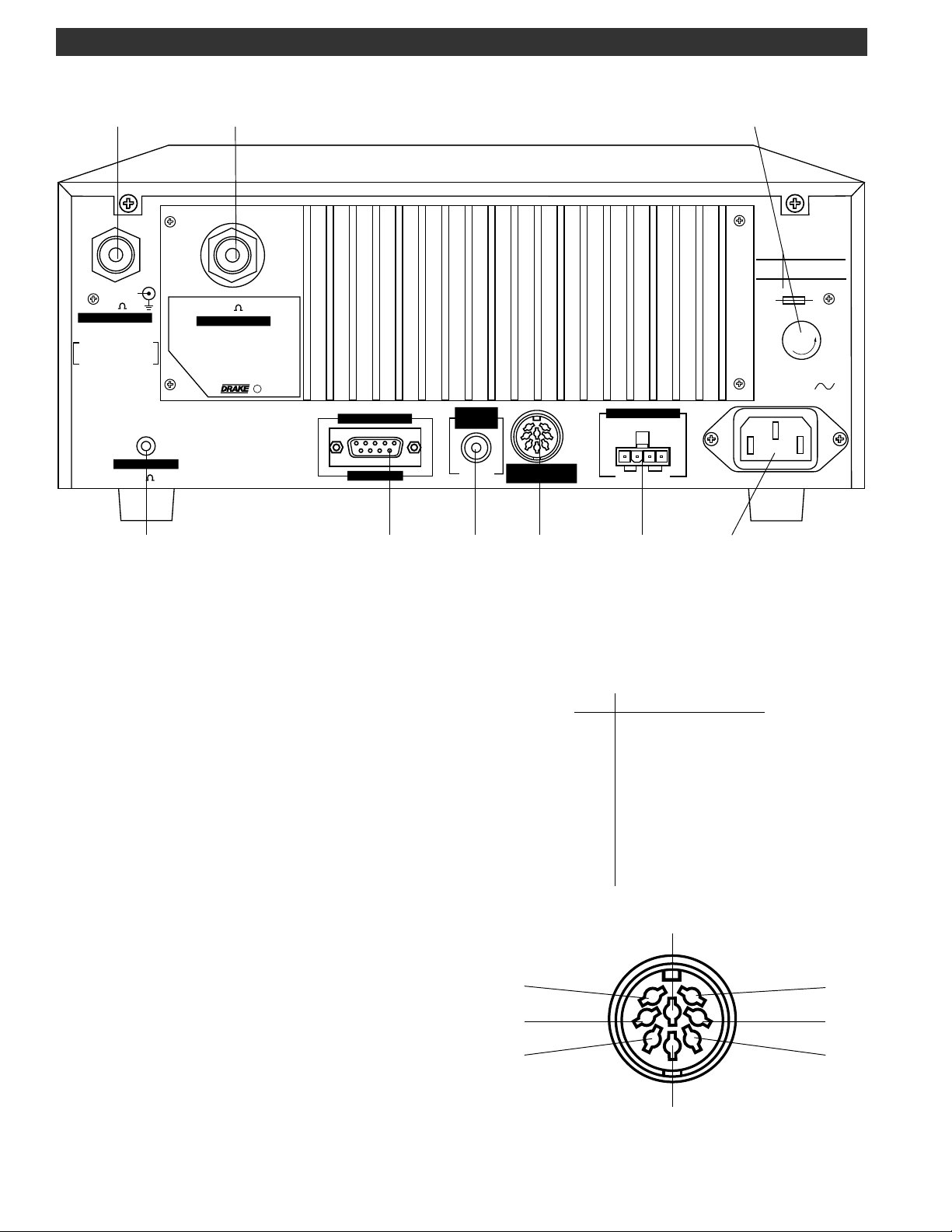
FIGURE 6 REAR PANEL
1) ANTENNA 1 - This connector is the antenna input/
output of Transceiver ‘A’. Attach a 50 Ohms nominal
impedance coaxial feed line from the antenna. Ensure
that the connected antenna is resonant in the 144 - 148
MHz (2-Meter) range prior to transmitting. This connector
accepts a standard PL-259 plug.
2) ANTENNA 2 - This connector is the antenna input to
Receiver ‘B’. Attach a 50 Ohms nominal impedance
coaxial feed line from the antenna. This connector
accepts a standard PL-259 plug.
3) Interface RS-232C - This 9-pin DB-9 connector provides
a standard RS-232C interface to a dumb terminal or PC.
Refer to the COMPUTER CONTROL section of this
manual.
4) FAX/DEMOD - This RCA connector is an audio input for
CW, RTTY, HF/FAX, or WEFAX encoded signals that are to
be demodulated by the optional DEMOD270 demodulator module. Input impedance is a nominal 600 Ohms.
Provide a nominal 250 mVolt signal level for proper
operation.
5) EXTERNAL TNC - This is an 8-pin DIN connector for an
optional external TNC. Refer to the TNC's Operation
Manual for wiring information. The pin numbers and
descriptions are as follows:
Pin#
1
2
3
4
5
6
7
8
Description
TX OUT (1200 B)
GND
PTT
RX IN (1200 B)
SQUELCH STATUS
TX OUT (9600 B)
RX IN (9600 B)
SPARE (open)
8
7
6
3
5
1
4
2
Page 16

Rear Panel Description, continued 11
6) DC INPUT - This connector is used for powering the
TR270 from an external DC source such as a car battery.
Observe proper polarity when wiring the mating connector. This input is UNFUSED and thus requires an
external (10 Amp, FAST BLOW) fuse to be wired in series
with the external wiring supplying this connector. The
transceiver will operate with a DC input voltage of 11-16
VDC. Full high power RF output during transmit is insured
with a nominal supply voltage of 13.6 VDC or higher.
7) AC Power Cord Receptacle - This receptacle accepts
a three-wire power cable. When the cable is connected to an appropriate power line outlet, the instrument is grounded. The unit is factory set and fused for
operation on a nominal 115 VAC, 50/60 Hz mains supply
and is shipped with a cord assembly intended for 115
VAC mains supply. Be certain of the mains supply
voltage prior to connecting this unit. For operation of
this unit on a nominal 230 VAC mains supply, refer to the
SAFETY/VOLTAGE SELECTION section in this manual for
internal connections and fusing value. Also use the
proper cable assembly approved by your local codes
for operation of this unit on nominal 230 VAC mains
supplies.
8) AC Line FUSE - This unit is factory set for operation on
nominal 115 VAC mains supply and a 3A, 250 V, SLO-BLO
(5 x 20 mm) fuse is installed. For operation of this unit on
a nominal 230 VAC mains supply, refer to the SAFETY/
VOLTAGE SELECTION section of this manual for internal
connections and fusing value.
9) External Speaker - This connector accepts a standard
1/8" diameter, 2-circuit, (monaural) phone plug for
connection of an 8-Ohm external speaker. Inserting the
phone plug into this connector switches off the internal
speaker.
Page 17

12 Getting Started
TR270 FM Transceiver
POWER
MIC
VOLUME
A
B
SQUELCH
REV
+
NUM
TEMP
SCAN
DEC
DTMF
ENC
TOT
PRIO
RPT
DTMF
NUM
HOLD TO SCAN
5
89
0
LOCK
123
4
7
*
SAT
DATA
WXSAT
VOICE
A MODE B
MEM
VFO
6
REV
SAT
B BW
CTS
#
STORE
VOICE
DATA
A
B
C
D
A / B
MODE
P. OUT
SETUP
W
N
LOCKED
SETUP
LMH
VFO 1
VFO 2
A
B
VFO 1
VFO 2
DCDCONMAIL
XMT
TNC STATUS
TUNING
PW
MEM
TX
RX
RX
PW
MEM
STA
SQUELCH
COUNTER-CLOCKWISE
GENERAL OPERATING INFORMATION
This transceiver is easy to use. Please take a few moments to read through this section and familiarize
yourself with general operating information.
BEEP TONES
The transceiver responds to all button depressions with
an audible beep (unless the function is deactivated).
They are as follows:
1 short tone for any button depression (if enabled within
the Setup Menu).
3 short, rapid succession tones for confirmation.
1 long, low tone for any invalid button depressions.
VOLUME
COUNTER-CLOCKWISE
FIGURE 7
3. Connect the transceiver to a source of AC power.
Switch power on to the TR270 with the POWER switch.
The front panel display should light and show VFO 1
selected for Receiver ‘A’. If the upper frequency display
is not shown (Standby condition), press the
to display ‘VOICE’ in the lower left-hand portion of the
display. Note that the frequency is displayed.
4. Adjust the appropriate VOLUME control (‘A’ or ‘B’) for
a comfortable listening level.
5. Tune to the desired receive frequency by using one of
several methods covered in this section.
PLEASE NOTE: A ‘ ’ box
around ‘A’ or ‘B’ indi-
cates whether transceiver ‘A’ or receiver ‘B’
can be tuned.
B
button
MODE
GETTING STARTED
1. Make certain that an antenna is connected to the
appropriate rear panel ANTENNA ‘1’ connector. It is
important that this antenna is resonant in the 144 148 MHz range and is capable of handling 25 Watts
transmit RF power. An additional antenna can be
connected to the ANTENNA ‘2’ connector at this time
also, if desired.
2. Please refer to FIGURE 7 and adjust the controls as
shown.
Connect the microphone.
6. Adjust the SQUELCH control at any time to set the
desired received signal strength required to unmute the
audio. Usually this control is set to a point that just quiets
the receiver when not tuned to a station, and is for
example, receiving noise. Rotating the control clockwise requires stronger signals to open the squelch.
7. Prior to transmitting, set low, medium, or high power
C
for transmit by pressing the
P. OUT
button.
Page 18

6
SAT
STORE
#
Getting Started cont'd. 13
8. Press the microphone PTT button and begin speaking.
The transmitted signal frequency is displayed during
transmit.
9. To receive on the ‘B’ receiver, Press the
A
button to
A / B
display a box around the ‘B’ (B) adjacent to the lower
frequency (7-digit) readout. If the lower frequency
B
display is not shown (Standby condition), press the
MODE
button to display ‘VOICE’ in the lower center portion of
the display. Tune to the desired receive frequency by
using one of several methods covered in this section
(same methods as used for the ‘A’ receiver).
DUAL VFO’s
TRANSCEIVER ‘A’ VFO 1 and VFO 2
Two VFO’s (1 and 2) are provided for the ‘A’ transceiver.
Selection is made with the
2
button when ‘A’ is
VFO
selected. Each VFO can be set to any frequency in the
‘A’ tuning range and act as a temporary memory
location.
For example, suppose you want 146.190 MHz in VFO 2
while using VFO 1 to tune other frequencies.
2
Press
Press
cies as desired. To recall VFO 2, Press the
to select VFO 2 and tune to 146.190 MHz.
VFO
2
to select VFO 1 and then tune other frequen-
VFO
2
button.
VFO
RECEIVER ‘B’ VFO 1 and VFO 2
Two VFO’s (1 and 2) are also provided for the ‘B’ receiver. Selection is made with the
2
button when
VFO
B
is displayed. Each VFO can be set to any frequency in
the ‘B’ tuning range and act as a temporary memory
location. Programming is the same as explained for
transceiver ‘A’.
VFO 1 = VFO 2
This function is used to transfer the frequency of the
active VFO into the inactive VFO. This is handy if you are
tuning and would like to temporarily hold a certain
frequency as you continue tuning. For example, suppose you are tuning in VFO 1 and come across a station
at 146.190 MHz you would like to occasionally check.
Press the
#
button followed by
STORE
2
(3 confirmation
VFO
beeps). Continue tuning and recall the station at
146.190 MHz anytime by Pressing the
2
VFO
button.
FREQUENCY STEP SELECTION
- Tuning Wheel Steps
Transceiver ‘A’: The transceiver can be programmed
within the SETUP menu to tune in 5, 10, 15, 20, or 25 kHz
steps.
The tuning wheel incorporates two-speed tuning.
Rotating the tuning wheel faster, results in an increased
tuning speed.
/ Button Steps
-
The button increases and the button decreases
the frequency by fixed 1 MHz step increments with each
depression. The button may be held to auto-repeat the
frequency change.
DIRECT FREQUENCY ENTRY
Direct keyboard entry of a frequency for either transceiver ‘A’ or receiver ‘B’ is possible by pressing the
*
NUM
button followed by the numeric buttons 0-9 (decimal
point understood). With no activity, ‘NUM’ times out in
approximately 3 seconds.
Transceiver ‘A’: Ensure that ‘A’ is selected. Press
*
NUM
followed by a numeric entry (6-digits maximum, 3-digits
minimum) in the range of 144.000 to 148.000 MHz.
For example: Enter 146.190 MHz
With ‘A’ selected,
Press
Press
Receiver ‘B’: Ensure that B is displayed. Press
(NUM is selected)
*
NUM
4
1
PRIO
6
RPT
SAT
9
1
PRIO
0
B BW
LOCK
*
NUM
followed by a numeric entry (7-digits maximum, 3-digits
minimum) in the range of 136.0000 to 174.0000 MHz or
420.0000 to 470.0000 MHz.
For example: Enter 162.4750 MHz
With ‘B’ selected,
Press
Press
(NUM is selected)
*
NUM
1
PRIO
2
VFO
7
4
RPT
5
DTMF
0
REV
LOCK
A partial frequency may be stored quickly by using the
button. A minimum of three valid digits must be
entered.
For example: Enter 144 MHz
with 'A' selected,
Press
Press
(NUM is displayed)
*
NUM
4
1
PRIO
4
RPT
RPT
#
STORE
Receiver ‘B’: The receiver can be programmed within
the SETUP menu to tune in 5, 10, 12.5, 15, 20, or 25 kHz
steps.
Page 19

14 Setup Menu
SETUP
D
NOTE: The SETUP mode can be entered only from the
Priority, VFO, or Memory states (and from the special
case of Inband or Crossband Repeater configuration).
Press and hold the
POWER
MIC
D
button to display the SETUP menu:
SETUP
TR270 FM Transceiver
VOLUME
SQUELCH
A
B
RESTORE FACTORY SETUP SETTINGS
The TR270 is factory programmed for the default SETUP
settings as shown in this section of the manual. To
restore ALL factory SETUP settings: - With power off,
press and hold the
button while switching the
power on.
SETUP MODE FUNCTION OPTION/PARAMETER
W
N
LOCKED
SETUP
SETUP
LMH
VFO 1
VFO 2
A
B
VFO 1
VFO 2
DCDCONMAIL
XMT
TNC STATUS
TUNING
PW
MEM
TX
RX
RX
PW
MEM
STA
REV
+
NUM
TEMP
SCAN
DEC
DTMF
ENC
TOT
PRIO
RPT
DTMF
NUM
HOLD TO SCAN
5
89
0
LOCK
123
4
7
*
SAT
DATA
WXSAT
VOICE
A MODE B
MEM
VFO
6
REV
SAT
B BW
CTS
#
STORE
VOICE
DATA
A
B
C
D
A / B
MODE
P. OUT
SETUP
In numeric entry mode,
press to clear a numeric
field.
SETUP MODE
NUMBER FUNCTION
0 0
0 1
0 2
Automatic Repeater
Transmit Offset
Set ANTENNA 2 DC
Power On or Off
Priority Channel
Action
In numeric entry mode,
press for quick frequency
entry. (Minimum of three
digits required).
OPTION / PARAMETER
DESCRIPTION
0 = no offset
1 = automatic offset
0 = Off
1 = On
0 = lock onto detected
carrier on designated
Priority channel
1 = sound audible beep
when a carrier is detected
on the Priority channel
Press and hold
to enter the
SETUP mode.
Press to exit the
SETUP mode.
These buttons set
the desired
option or parameter.
DISPLAY
(factory defaults shown)
SETUP
SETUP
SETUP
Rotate to select
the desired SETUP
function number.
0 or 1
0 or 1
0 or 1
Page 20

Setup Menu, continued 15
SETUP MODE
NUMBER FUNCTION
0 3
0 4
0 5
0 6
Flow Control for RS232
Transmission and
Reception
Tuning Wheel
Step Size Receiver 'A'
Tuning Wheel
Step Size Receiver 'B'
Assign Internal TNC
OPTION / PARAMETER
DESCRIPTION
0 = No flow control
1 = Hardware handshaking
Set:
5, 10, 15, 20, or 25 kHz
Set:
5, 10, 12.5, 15, 20, or 25 kHz
0 = no TNC installed or
unassigned
1 = assign to Transceiver 'A'
2 = assign to Receiver 'B'
DISPLAY
(factory defaults shown)
SETUP
SETUP
SETUP
SETUP
0 or 1
0, 1 or 2
0 7
0 8
0 9
1 0
Assign External TNC
External TNC Data
Rate (if connected)
DTMF Transmit Delay
Demodulator Source
(if DEMOD 270 demodulator card is
installed)
0 = no TNC connected or
unassigned
1 = assign to Transceiver 'A'
2 = assign to Receiver 'B'
Set:
1200 or 9600
Set:
Delay = 250 mSec. X N
where N = 0, 1, 2, 3, 4
0 = audio source internal to
TR270
1 = audio source external to
TR270
SETUP
SETUP
SETUP
SETUP
0, 1 or 2
0, 1, 2,
3, 4
0 or 1
1 1
Demodulation Type
(if DEMOD 270 demodulator card is
installed)
0 = AM demodulation
1 = FM demodulation
SETUP
0 or 1
Page 21

16 Setup Menu, continued
SETUP MODE
NUMBER FUNCTION
1 2
Set audible beep on
or off for any button
depression
1 3
Set for Normal or
Crossband Repeater
mode
1 4
1 5
Time - Out - Timer on
Transmit
Assign Antenna
Input(s) to Receiver 'B'
(Receiver A Input is
always from
ANTENNA 1)
OPTION / PARAMETER
DESCRIPTION
0 = no audible beep when
button is pressed
1 = audible beep when
button is pressed
0 = normal mode
1 = repeater mode
Set:
0, 1, 2, 3, or 10 minutes
0= no time out
0 = Auto selection
Frequency
136-174MHz
420-470 MHz
Receiver B Input
ANTENNA 1
ANTENNA 2
1 = Auto selection
Frequency
142-150MHz
136-142MHz
150-174MHz
420-470 MHz
Receiver B Input
ANTENNA 1
ANTENNA 2
ANTENNA 2
ANTENNA 2
DISPLAY
(factory defaults shown)
SETUP
SETUP
SETUP
SETUP
0 or 1
0 or 1
0, 1, 2
or 3
16
17
18
19
20
Methods for VFO
SCAN Stop Receiver A
Methods for VFO
SCAN Stop Receiver B
Methods for
Memory SCAN Stop Receiver A
Methods for
Memory SCAN Stop Receiver B
Receiver A - Program
START frequency
endpoint for
VFO Scan
2 = RECEIVER B Input
is ANTENNA 1
3 = RECEIVER B Input
is ANTENNA 2
For Setups #16,17,18, 19:
SEEK (0) - Stop scan at first
detected carrier and exit
the scan mode.
CARRIER (1) - Stop scan at
a detected carrier, then
resume scan 5 seconds
after carrier drops.
TIME (2) - Stop scan at a
detected carrier, wait 5
seconds, and then resume
scan.
RESUME (3) - Stop scan at
a detected carrier and
resume scan immediately
after carrier drops.
Enter frequency (for
example: 144.0000)
NUM
SETUP
SETUP
SETUP
SETUP
SETUP
0, 1, 2
or 3
0, 1, 2
or 3
0, 1, 2
or 3
0, 1, 2
or 3
Page 22

Setup Menu, continued 17
SETUP MODE
NUMBER FUNCTION
21
Receiver A - Program
STOP frequency
endpoint for
VFO Scan
22
Receiver B - Program
START frequency
endpoint for
VFO Scan
23
Receiver B - Program
STOP frequency
endpoint for
VFO Scan
24
25
Set Mode of Memory
Scan for Receiver A
Receiver A: Program
Memory Channel
Number to Define
START Endpoint for
Range Scan
OPTION / PARAMETER
DESCRIPTION
Enter frequency
(for example: 148.0000)
Enter frequency
(for example: 136.0000)
Enter frequency
(for example: 470.0000)
0 = All memory channels
(00 - 99 possible)
1 = A range of memory
channels
2 = A list of memory
channels (one list of 10
channels)
Press
/ to set desired
number 00-99
(for example: 00)
NUM
NUM
NUM
DISPLAY
(factory defaults shown)
SETUP
SETUP
SETUP
SETUP
SETUP
0, 1, or 2
26
27
28
29
Receiver A: Program
Memory Channel
Number to Define
STOP Endpoint for
Range Scan
Set Mode of Memory
Scan for Receiver 'B'
Receiver 'B': Program
Memory Channel
Number to Define
START Endpoint for
Range Scan
Receiver 'B': Program
Memory Channel
Number to Define
STOP Endpoint for
Range Scan
Press
/ to set desired
number 00-99
(for example: 99)
0 = All memory channels
(00 - 99 possible)
1 = A range of memory
channels
2 = A list of memory
channels (one list of 10
channels)
Press
/ to set desired
number 00-99
(for example: 00)
Press
/ to set desired
number 00-99
(for example: 99)
SETUP
SETUP
SETUP
SETUP
0, 1, or 2
Page 23

18 Setup Menu, continued
SETUP MODE
NUMBER FUNCTION
30
.
.
39
40
.
.
49
Receiver A:
Construct Memory
Channel List
(ten lists with a
maximum of 10
channels each listSetup 30 - 39)
Receiver 'B':
Construct Memory
Channel List
(ten lists with a
maximum of 10
channels each listSetup 40 - 49)
OPTION / PARAMETER
DESCRIPTION
30 = List #0
31 = List #1
.
.
.
38 = List #8
39 = List #9
40 = List #0
41 = List #1
.
.
.
48 = List #8
49 = List #9
NUM
List index 0 - 9
with
List index 0 - 9
with
NUM
DISPLAY
(factory defaults shown)
SETUP
Enter a 2-digit memory
number.
*
Press
entry.
SETUP
Enter a 2-digit memory number.
Press
to clear the
NUM
*
to clear the entry.
NUM
30 - 39
40 - 49
50
51
52
53
54
Set Low level Transmit
Power
Set Medium level
Transmit Power
Set High level Transmit
Power
Sets the scanned
frequency range for
the SAT SCAN operation
Sets the time
between frequency
adjustments for the
SAT LOCKED (Doppler
Tracking) operation
NOTE: Power output is
factory set as follows:
LOW - 1 Watt, nominal
MEDIUM - 10 Watts, nominal
HIGH - 25 Watts, nominal
The parameters shown are
for example only. For each
level, Low, Medium, or High,
press
factory set parameter ±3
counts. This action will vary
the power ± of the factory
set power. Actual power
output can be checked with
a calibrated RF Wattmeter, if
desired.
Press
Tuning range of the Scan
Start frequency, in kHz (for
example, to set ± 10 kHz
range, set the number 10).
Press
between frequency adjust-
ments, (for example, to set
0.5 second, set the number
05).
/ to modify the
/ to set the ±
/ to set the time
SETUP
SETUP
SETUP
SETUP
00 = ±0 Hz
01 = ±1 kHz
.
.
.
99 = ±99 kHz
SETUP
00 = 0 Second
01 = 0.1 Second
.
.
.
99 = 9.9 Seconds
Parameters
are shown
for example
only.
Page 24

Setup Menu, continued 19
SETUP MODE
NUMBER FUNCTION
55
56
Sets the delay time
between the end of a
SAT LOCKED condition
and the continuation
of SAT SCAN
Set LCD backlight
intensity
OPTION / PARAMETER
DESCRIPTION
Press
time prior to resuming SAT
SCAN, (for example, to set
5 seconds, set the number
05).
Press
relative intensity level (for
example: 99)
/ to set the Delay
/ to set the
DISPLAY
(factory defaults shown)
SETUP
00 = SAT SCAN
does not resume
01 = 1 Second
before SAT SCAN
resumes
.
.
.
99 = 99 Seconds
before SAT SCAN
resumes
SETUP
00 = Dim
.
.
.
99 Bright
57
58
59
60
Set repeater mode
high pass audio filter
on or off
Set transmit microphone audio filter on
or off
Set Receiver 'A'
subaudible tone filter
on or off
Set Receiver 'B'
subaudible tone filter
on or off
0 = filter off
1 = filter on
0 = filter off
1 = filter on
0 = filter off
1 = filter on
0 = filter off
1 = filter on
SETUP
SETUP
SETUP
SETUP
0 or 1
0 or 1
0 or 1
0 or 1
Page 25
20 Memory Functions
STORE
#
STORE
#
The TR270 has 400 programmable memory locations that
are allocated as follows:
Transceiver ‘A’: 100 memories.
Receiver ‘B’: 100 memories, plus 100 additional memories
assigned to ‘WXSAT’.
‘SAT’ (satellite) mode: 100 memories
These memories can be used to store and recall commonly monitored or operated frequencies. Additionally,
two different VFO frequencies and a priority frequency
can be programmed for each of transceiver ‘A’ and
receiver ‘B’.
With memory locations programmed, various scan
functions can be used to automatically monitor desired
memory frequencies. The following may be stored in
appropriate memory locations:
1) Frequency
2) Transceiver ‘A’: Simplex or Repeater mode with ±
offset.
3) VOICE or DATA mode
4) Transceiver ‘A’: CTCSS Encoder and/or Decoder
status and frequency.
Receiver ‘B’: CTCSS Decoder status and frequency.
5) Lock / unlock status
MEMORY CHANNEL PROGRAMMING
Select a frequency by any tuning or selection method.
Selection methods include:
1) Press the
2) Press the
1
button to select the PRIORITY frequency.
PRIO
2
button to select one of two VFO
VFO
frequencies for the selected transceiver ‘A’ or for
receiver ‘B’.
3) Press the
memory locations. Turn the tuning wheel, press
buttons, or press
3
button to select 1 of 100 possible
MEM
followed by a 2-digit number
*
NUM
/
entry (00-99) for the desired memory location.
Make any adjustments desired, for example; CTS or RPT
settings.
- To load successive memory locations quickly, start in
the VFO mode with the first desired frequency and the
desired starting memory channel number. From the VFO
#
mode, press
3
,
,
to store the displayed
STORE
MEM
frequency to the previously displayed memory number,
advance the memory channel by one, and return to the
VFO mode. Tune to a new frequency and Press
3
,
MEM
. Continue repeating the process.
#
STORE
,
RECALLING A MEMORY CHANNEL
3
From the VFO mode, Press the
and a 2-digit numeric entry corresponding to the
*
NUM
button followed by
MEM
desired memory channel. From the MEMORY mode,
additional memory channels are tuned by turning the
tuning wheel, using the
the memory channel, or by pressing
/ buttons to increment
followed by a
*
NUM
2-digit numeric entry. To frequency tune after recalling
#
a memory channel, press
tion beeps, press the
2
VFO
tune as desired using the tuning wheel,
2
,
STORE
. After the confirma-
VFO
button and then frequency
/
buttons, or by direct numeric entry.
CHANGING A MEMORY CHANNEL
An individual memory channel is changed by storing a
new frequency and associated parameters to the same
location.
CONSTRUCT A MEMORY LIST
10 lists (0-9), each containing a maximum of any 10
memory channels (00-99 available), can be constructed
for both receiver ‘A’ and receiver ‘B’ for the purpose of
scanning the channels contained in the respective lists.
Receiver ‘A’:
Setup Mode #24 - set for ‘2’, and
Setup Mode #30 - Selects list #0. Construct the list with a
maximum of 10 channels. From Setup #30, index from 0-
Whatever is displayed can be stored by one of the
following procedures:
- Press
#
followed by
STORE
2
to store the displayed
VFO
frequency into the selected VFO.
- Press
#
followed by
STORE
1
to store the displayed
PRIO
frequency into the priority channel.
- Press
#
followed by
STORE
3
for a flashing memory
MEM
number indication. Enter a 2-digit number (00-99) using
the numeric buttons (this operation automatically
function shifts the buttons to the NUM mode) to store the
displayed frequency to the desired memory location.
9 with the / buttons, Press
followed by a 2-
*
NUM
digit numeric entry for each desired memory channel.
SETUP
NUM
SETUP
List index 0 - 9
with
Enter a 2-digit memory
number, or press
*
NUM
the entry.
to clear
Page 26

Receiver ‘B’:
Setup Mode #27 - set for ‘2’, and
Setup Mode #40 - Selects list #0. Construct the list with a
maximum of 10 channels. From Setup #40, index from 0-9
with the
/ buttons, Press
followed by a 2-
*
NUM
digit numeric entry for each desired memory channel.
SETUP
NUM
SETUP
Memory Functions, continued 21
RESTORE FACTORY MEMORY PROGRAMMING
3
With power off, press and hold the
while switching the power to ‘On’. This action does
the following:
- initializes all 400 memory channels, including
standard repeater and packet frequencies in
transceiver ‘A’.
- clears all DTMF phone numbers.
- initializes all power-on variables.
- initializes priority channels.
- disables MARS/CAP operation.
MEM
button
List index 0 - 9
with
Enter a 2-digit memory
number, or press
*
NUM
clear the entry.
to
LOCKING A MEMORY CHANNEL
Memory channels tagged with the
symbol will be
skipped during the scan process.
First be sure the receiver is in the VFO mode (MEM or
SCAN not displayed).
A) Press
with the
3
and select the desired memory location
MEM
/ buttons, or by direct entry of a two-
digit memory channel number.
B) To lock out a memory channel: Press
0
LOCK
. The
symbol lights adjacent to the memory channel number.
To unlock a memory channel, Press
0
. The symbol
LOCK
will extinguish.
Page 27

22 Scan Functions
The TR270 is capable of several different methods and
modes of scanning frequencies.
Both Receiver ‘A’ and Receiver ‘B’ provide the following:
Scan Mode: Either VFO or Memory
Scan Method:
SEEK (0) - Stop scan at first detected carrier and exit the
scan mode.
CARRIER (1) - Stop scan at a detected carrier, then
resume scan 5 seconds after carrier drops.
TIME (2) - Stop scan at a detected carrier, wait 5
seconds, and then resume scan.
RESUME (3) - Stop scan at a detected carrier, then
resume scan immediately after carrier drops.
Additionally, the subaudible tone squelch may be
enabled for either receiver. Either a VFO or Memory
scan may be initiated for each receiver.
A mode and a method are programmed together.
Before performing any scan functions,
please read NOTE 1 and NOTE 2.
NOTE 1:
First, it is important to understand how SCAN Range
works. Example A refers to two types of VFO scan and
Example B refers to two types of Memory scan.
Example A: VFO SCAN
1) Programmed (in SETUP) START frequency limit is lower
than the programmed STOP frequency limit:
Direction control during scan: Direction control during scan:
START
limit
(frequency)
= direction when
= direction when
SCAN COVERAGE
is used
is used
STOP
limit
(frequency)
- OR -
2) Programmed (in SETUP) START frequency limit is higher
than the programmed STOP frequency limit:
JUMP
STOP limit START limit
(EXCLUDED COVERAGE)
Receiver
coverage
End limit
Direction control during scan:
= direction when is used
= direction when
is used
Receiver
coverage
End limit
Example B: MEMORY SCAN
1) Programmed (in SETUP) START memory channel number
limit is lower than the programmed STOP memory channel
number limit:
START
limit
= direction when is used
= direction when
SCAN COVERAGE
is used
STOP
limit
- OR -
2) Programmed (in SETUP) START memory channel number
limit is
higher than the programmed STOP memory channel
number limit:
STOP limit
(MEM number)
Receiver
coverage
End limit
(EXCLUDED COVERAGE)
Direction control during scan:
= direction when is used
= direction when
JUMP
START limit
(MEM number)
Receiver
coverage
End limit
is used
Page 28

Scan Functions, continued 23
SETUP
A / B
A
3
MEM
3
MEM
A / B
A
3
MEM
3
MEM
NOTE 2:
1. Signal detection (stop scan on detected carrier) is
dependent upon the strength of the signal, the squelch
control setting, and the status of the preprogrammed
subaudible tone squelch decoder (CTCSS “off” or “on”).
2. Press the
/ buttons during scan to reverse the
direction of scan, if desired. When starting a scan, the
direction is always the same as the last time a scan was
ended.
3. To interrupt a scan on either receiver, first press the
A
button to select the particular receiver. Press the
A / B
3
2
,
MEM
VFO
, or
1
to exit the scan mode for that se-
PRIO
lected receiver.
4. While one receiver is being scanned, the opposite
receiver (transceiver) can be operated in the normal
mode, or set to scan simultaneously.
5. The receiver can be tuned during scan, if desired. It
may be useful to tune away from an active frequency,
to resume scanning, for example (in all scan stop
methods except SEEK). A frequency can also be
entered during scan (press
followed by numeric
*
NUM
entry). After the carrier drops (CARRIER and RESUME) or
timeout (TIME) on the tuned frequency, the scan will
resume within the programmed (in SETUP) range limits.
SCAN MEMORY
- SCAN ALL UNLOCKED MEMORY CHANNELS
For Receiver ‘A’:
1) Select SETUP #24 - set to ‘0’
SETUP
2) Select SETUP #18 - set to: ‘0’ for a Seek scan
‘1’ for a Carrier scan
‘2’ for a Time scan
‘3’ for a Resume scan
3) Exit the SETUP mode.
4) Press the
5) Press and hold the
Press the
button to select Receiver‘A’.
button to start the scan.
/ buttons during scan to reverse the
scan direction, if desired.
6) Press the
2
,
1
, or
VFO
button to exit the scan
PRIO
mode.
For Receiver ‘B’:
1) Select SETUP #27 - set to ‘0’.
Press and hold the
and hold the
2
button to start a VFO scan. Press
VFO
3
button to start a Memory scan. In all
MEM
cases, prior to starting a scan, adjust the SQUELCH
control for the appropriate receiver to a setting that just
quiets the receiver.
SETUP
2) Select SETUP #19 - set to: ‘0’ for a Seek scan
‘1’ for a Carrier scan
‘2’ for a Time scan
SETUP
‘3’ for a Resume scan
3) Exit the SETUP mode.
4) Press the
5) Press and hold the
button to select Receiver ‘B’.
button to start the scan.
Press the / buttons during scan to reverse the
scan direction, if desired.
6) Press the
2
,
1
, or
VFO
button to exit the scan
PRIO
mode.
Page 29

24 Scan Functions, continued
3
MEM
-SCAN ALL UNLOCKED MEMORY CHANNELS WITHIN A
PROGRAMMED RANGE OF MEMORY CHANNELS.
For Receiver ‘A’:
1) Select SETUP #24 - set to ‘1’.
SETUP
2) Select SETUP #25 - set to the desired memory channel
number to define the START endpoint for a Range Scan.
SETUP
3) Select SETUP #26 - set to the desired memory channel
number to define the STOP endpoint for a Range Scan.
SETUP
4) Select SETUP #18 - set to: ‘0’ for a Seek scan
‘1’ for a Carrier scan
‘2’ for a Time scan
‘3’ for a Resume scan
SETUP
5) Exit the SETUP mode.
6) Press the
7) Press and hold the
A
button to select Receiver ‘A’.
A / B
3
button to start the scan.
MEM
Press the / buttons during scan to reverse the
scan direction, if desired.
8) Press the
3
2
,
MEM
VFO
, or
1
button to exit the scan
PRIO
mode.
For Receiver ‘B’:
1) Select SETUP #27 - set to ‘1’.
SETUP
4) Select SETUP #19 - set to: ‘0’ for a Seek scan
‘1’ for a Carrier scan
‘2’ for a Time scan
SETUP
‘3’ for a Resume scan
5) Exit the SETUP mode.
6) Press the
7) Press and hold the
A
button to select Receiver ‘B’.
A / B
3
button to start the scan.
MEM
Press the / buttons during scan to reverse the
scan direction, if desired.
8) Press the
3
2
,
MEM
VFO
, or
1
button to exit the scan
PRIO
mode.
-SCAN A LIST OF MEMORY CHANNELS
(ONE LIST OF 10 CHANNELS)
For Receiver ‘A’:
Select LIST scanning:
1) Select SETUP #24 - set to ‘2’.
SETUP
Select a List and Setup channels in the List:
2) Select SETUP #30 (List #0) through #39 (List #9).
NUM
SETUP
3) Construct the list by pressing the / buttons to
select the List index number (0 - 9) and entering the
desired 2-digit memory channel number at that se-
lected List index number. [Press
to clear a List index
*
NUM
number (— will appear at a cleared List index number)].
- Setup additional lists by repeating steps 2 and 3.
Select a Scan STOP method:
4) Select SETUP #18 - set to: ‘0’ for a Seek scan
‘1’ for a Carrier scan
‘2’ for a Time scan
SETUP
‘3’ for a Resume scan
2) Select SETUP #28 - set to the desired memory channel
5) Exit the SETUP mode.
number to define the START endpoint fo a Range Scan.
To start a List scan:
SETUP
6) Press the
7) Press and hold the
3) Select SETUP #29 - set to the desired memory channel
number to define the STOP endpoint for a Range Scan.
numeric entry of the desired List index number (0 -9), to
start the scan.
8) Press the
SETUP
A
button to select Receiver ‘A’.
A / B
button, followed by the
3
2
,
MEM
VFO
, or
1
to exit the scan mode.
PRIO
Page 30

Scan Functions, continued 25
A / B
A
2
VFO
3
MEM
For Receiver ‘B’:
Select LIST scanning:
1) Select SETUP #27 - set to ‘2’.
SETUP
Select a List and Setup channels in the List:
2) Select SETUP #40 (List #0) through #49 (List #9).
NUM
SETUP
3) Construct the list by pressing the / buttons to
select the List index number (0 - 9) and entering the
desired 2-digit memory channel number at that selected List index number. [Press
to clear a lIst index
*
NUM
number (— will appear at a cleared List index number)].
- Setup additional lists by repeating steps 2 and 3.
Select a Scan STOP method:
4) Select SETUP #19 - set to: ‘0’ for a Seek scan
‘1’ for a Carrier scan
SETUP
‘2’ for a Time scan
‘3’ for a Resume scan
5) Exit the SETUP mode.
SCAN VFO
A VFO scan permits continuous tuning of frequencies
between two programmed limits.
For Receiver ‘A’:
1) Select SETUP #20 - enter the START frequency endpoint
from 144 - 148 MHz.
NUM
SETUP
*
2) Select SETUP #21 - enter the STOP frequency endpoint
from 144 - 148 MHz.
NUM
SETUP
*
3) Select SETUP #04 - set to 5, 10, 15, 20, or 25 kHz step
size.
SETUP
4) Select SETUP #16 - set to: ‘0’ for a Seek scan
‘1’ for a Carrier scan
‘2’ for a Time scan
‘3’ for a Resume scan
SETUP
To start a List scan:
6) Press the
7) Press and hold the
A
button to select Receiver ‘B’.
A / B
3
button, followed by the
MEM
numeric entry of the desired List index number (0 - 9), to
start the scan.
8) Press the
3
2
,
MEM
VFO
, or
1
to exit the scan mode.
PRIO
5) Exit the SETUP mode.
6) Press the
button to select Receiver ‘A’.
7) Press and hold the
Press the
/ buttons during scan to reverse the
scan direction, if desired.
8) Press the
2
,
, or
VFO
button to start the scan.
1
to exit the scan mode.
PRIO
*142-150 MHz operation with proof of MARS and CAP license.
Page 31

26 Scan Functions, continued
For Receiver ‘B’:
1) Select SETUP #22 - enter the START frequency endpoint
from 136 - 174 MHz or 420 - 470 MHz.
NUM
SETUP
2) Select SETUP #23 - enter the STOP frequency endpoint
from 136 - 174 MHz or 420 - 470 MHz.
NUM
SETUP
3) Select SETUP #05 - set to 5, 10, 12.5, 15, 20, or 25 kHz
step size.
SETUP
4) Select SETUP #17 - set to: ‘0’ for a Seek scan
‘1’ for a Carrier scan
‘2’ for a Time scan
SETUP
‘3’ for a Resume scan
5) Exit the SETUP mode.
6) Press the
7) Press and hold the
Press the
A
button to select Receiver ‘B’.
A / B
2
button to start the scan.
VFO
/ buttons during scan to reverse the
scan direction, if desired.
8) Press the
3
2
,
MEM
VFO
, or
1
to exit the scan mode.
PRIO
LOCKING A MEMORY CHANNEL
Memory channels tagged with the symbol will be
skipped during the scan process.
3
A) Press
with the
and select the desired memory location
MEM
/ buttons, or by direct entry of a two-
digit memory channel number. If recalling an unprogrammed memory channel with direct entry, an error
beep is heard.
B) To lock out a memory channel: Press
0
. The
LOCK
symbol lights adjacent to the memory channel number.
To unlock a tagged memory channel, Press
0
. The
LOCK
symbol will disappear.
Page 32

4
RPT
Voice Operation 27
VOICE OPERATION
The TR270 is capable of FM voice operation over a
simplex or repeater frequency pair. Additionally, by
using receiver ‘B’, a crossband repeat function is also
available. Other selectable options include subaudible
tone encode/decode, receiver subaudible tone filter
selection, and full DTMF [Dual-Tone Multi Frequency;
Touch Tone ®] operation.
NOTE: VOICE/DATA modes can be stored using memory
channels. Factory defaults are set appropriately for
many areas of the United States.
FM SIMPLEX OPERATION
To receive:
1) Select receiver ‘A’ and VFO 1.
2) Tune to the desired frequency by either the main
tuning wheel,
/ buttons, or by direct entry.
3. Adjust the volume control for a comfortable listening
level.
4. Adjust the squelch control as required. The control is
usually set to a point where the receiver audio just mutes
when no stations are being received.
To transmit:
1) Be certain that the VOICE mode has been selected
with the
2) Press the
B
button.
MODE
4
button until ‘+’ or ‘-’ is extinguished. If
RPT
the indicated frequency is a standard simplex frequency, and SETUP #00 is set for ‘1’ (factory default
setting), the ‘+’ or ‘-’ will be automatically turned off.
C
3) Press the
button to select the desired transmit
P. OUT
power, remembering that it is good practice to use as
little power as necessary to establish a contact.
4) Monitor the frequency prior to actually transmitting to
ensure that you will not interfere with anyone else trying
to use the frequency.
5) Press and hold the PTT (Push-to-talk) button on the
microphone and speak into the microphone at a normal
voice level.
6) Release the PTT button when you are finished speaking to return the TR270 to the receive mode.
REPEATER OPERATION
Repeater operation allows communications over far
greater distances than the simplex mode usually provides. Typically the repeater is located on a tall structure
or mountain. Repeaters are designed to receive on a
certain input frequency and repeat on a different
output frequency. The input and output frequencies are
separated by an offset frquency, usually + or - 600 kHz.
Most amateur radio repeaters utilize this ‘Standard’
offset format. In some rare instances, this standard offset
is abandoned, and the input and output frequency
offset is a ‘Custom’ offset format. The TR270 is capable
of handling both ‘Standard’ and ‘Custom’ offsets.
STANDARD OFFSETS
TR270 Repeater Offsets (Auto mode, Setup #00 = 1):
Repeater Frequency Offset
(MHz)
144.000 - 145.095 Simplex
145.100 - 145.495 -600 kHz
145.500 - 145.995 Simplex
146.000 - 146.395 +600 kHz
146.400 - 146.595 Simplex
146.600 - 146.995 -600 kHz
147.000 - 147.395 +600 kHz
147.400 - 147.595 Simplex
147.600 - 147.995 -600 kHz
To receive:
1) Select the desired frequency as was described for the
Simplex mode of operation.
2) Adjust the volume control for a comfortable listening
level.
3) Adjust the squelch control as required.
To transmit:
1) Be certain that the VOICE mode has been selected
with the
2) Select a ‘Standard’ offset with the
B
MODE
button.
4
button appro-
RPT
priate for the repeater frequency. If the indicated
frequency is in a ‘Standard’ offset range as outlined in
the previously listed table, and SETUP #00 is set for ‘1’
(factory default setting), the TR270 will automatically
select and display the proper offset.
C
3) Press the
button to select the desired transmit
P. OUT
power. Usually a Low power setting is sufficient to ‘hit’
the repeater (provide a good quality signal to the
repeater).
4) Monitor the frequency prior to actually transmitting to
ensure that you will not interfere with anyone else trying
to use the repeater.
5) Press and hold the PTT (Push-to-talk) button on the
microphone and speak into the microphone at a normal
voice level. The display will change to indicate the
transmit frequency.
6) Release the PTT button when you are finished speaking to return the TR270 to the receive mode.
CUSTOM OFFSETS
Sometimes, the input and output frequencies of a
repeater will not follow a “standard” convention. For
example, the input frequency could be located at one
end of the 2-meter band, and the output located at the
other end of the band. This type of repeater would
require a “custom” offset. The TR270 is easily programmed for “custom” offsets.
B
1) Press the
MODE
button to set the VOICE mode, if not
already set.
2) Enter a valid transmit frequency in VFO 1.
3) Enter a valid receive frequency in VFO 2.
4) Press and hold the
button until both the ‘+’ and
‘-’ indicators are displayed.
Page 33

28 Voice Operation, continued
5) Monitor the frequency prior to actually transmitting to
ensure that there is no interference with others trying to
use the repeater.
6) Press and hold the PTT button on the microphone and
speak into the microphone at a normal voice level. The
display will change to indicate the transmit frequency.
7) Release the PTT button when you are finished speak-
ing to return the TR270 to the receive mode.
SUBAUDIBLE TONE OPERATION
The TR270 includes a subaudible encoder/decoder for
transceiver ‘A’ and a separate decoder for receiver ‘B’.
‘A’ and ‘B’ tone frequencies may be set independently
of each other. ‘A’ may be set to encode only, or to
encode and decode. Encoding only will be used when
you need to transmit the tone to open the subaudible
squelch of a repeater or of any other receiver with subaudible tone squelch activated, but you wish to hear
any signals that exceed the signal level threshold set by
the squelch control. If you desire the TR270 to only
respond to signals transmitting a subaudible tone, the
decode function may be activated as well. The status
of the encoder and decoder for transceiver ‘A’ is always
shown on the LCD display. To see the status of the
decoder for receiver ‘B’, press the
8
button once
CTS
when the ‘B’ receiver is selected for tuning.
If the TR270 is used frequently for receiving signals that
are transmitting continuous subaudible tones, it may be
desirable to reduce the level of the tone heard in the
speaker by enabling a high pass filter. Program SETUP
#59 for a ‘1’ to enable the filter for receiver ‘A’; program
SETUP #60 for a ‘1’ to enable the filter for receiver ‘B’. In
the repeat mode, program SETUP #57 for a ‘1’ to enable
a high pass filter in the audio path. Finally, if you are
using CTCSS encoding, and the receiving station
experiences “talk off” (squelching on voice peaks),
program SETUP #58 for a ‘1’ to enable a high pass filter
for the microphone audio. All of these high pass filters
have a cutoff frequency of approximately 300 Hz.
Expect some noticeable loss of low frequency audio
response if the filters are enabled.
Transceiver ‘A’ -
To Enable Tone Encode and /or Tone Encode/Decode:
Press the
1) Press the
A
button to select receiver ‘A’, if necessary.
A / B
8
button once, and within 3 seconds,
CTS
2) Dial in the desired subaudible tone frequency, using
the main tuning wheel.
3) With the tone frequency displayed, press the
8
CTS
button again to enable tone ENCode.
4) Press the
8
button again to enable tone ENCode/
CTS
DECode.
5) Press the
8
button again to turn the tone Off.
CTS
Receiver ‘B’ -
To Enable or Disable Tone Decoding:
Press the
1) Press the
A
button to select receiver ‘B’, if necessary.
A / B
8
button once to see the present setting
CTS
(‘OFF’ indicates that the decoder is disabled), and
within 3 seconds,
2) Rotate the tuning wheel or press
/ buttons to set
the desired tone frequency. Allow display to time out.
The encoder is now enabled.
Press the
setting. Press the
8
button at any time to review the current
CTS
8
button a second time before the
CTS
display times out to toggle between on (tone frequency
displayed) or ‘OFF’ without changing the programmed
decode frequency.
Subaudible Tone Table:
Nominal Tone Frequency (Hz)
67.0
69.3
71.9
74.4
77.0
79.7
82.5
85.4
88.5
91.5
94.8
97.4
100.0
103.5
107.2
110.9
114.8
118.8
123.0
127.3
131.8
136.5
141.3
146.2
151.4
156.7
159.8
162.2
167.9
173.8
179.9
183.5
186.2
189.9
192.8
196.6
199.5
203.5
206.5
210.7
218.1
225.7
229.1
233.6
241.8
250.3
254.1
DTMF OPERATION
Some repeaters use DTMF (Touch Tone ®) for control
purposes and to allow users of the repeater to make
telephone calls (Autopatch) through the repeater. The
TR270 is capable of generating DTMF tones for this
purpose.
DTMF Tone Table:
FREQUENCY (Hz) 1209 1336 1477 1633
697 123A
770 456B
852 789C
941 *0#D
The DTMF tones are available anytime the TR270 PTT is
pressed.
TO USE DTMF TONES
1) Press PTT on the microphone.
2) Press buttons 0-9, A-D, or *, #.
The microphone audio is muted during the time each
button is held.
The TR270 permits up to ten, 14-digit DTMF sequences to
be programmed and stored in memory. Additionally,
two methods of dialing are available.
Page 34

Voice Operation, continued 29
A / B
A
A / B
A
NUM
*
SETUP
SETUP
SETUP
D
H
VOICE
VOICE
LOCKED
N
TX
VFO 1
RX
VFO 1
A
B
SETUP
TO STORE A PHONE NUMBER
1) Press the
7
button, and within 5 seconds, Press 0-9
DTMF
to select a DTMF sequence memory location.
2) Begin entering the phone number. The display will
automatically scroll the entered numbers to the left. To
view or edit a phone number, rotate the main tuning
wheel to scroll and highlight the desired digit that is to
be edited. The digit will flash. Enter the new number at
that digit location.
3) To erase the entered number and start over, Press the
button to clear the display.
4) When all numbers have been entered, Press the
button to store the number.
TO TRANSMIT A STORED PHONE NUMBER
DIALING IF THE PHONE NUMBER IS TO BE DISPLAYED
1) Press the
7
button, and within 3 seconds,
DTMF
2) Select 0-9 (stored phone number will be displayed).
3) Press PTT on the microphone.
4) The displayed phone number will be transmitted after
any delay as set by setup #9.
5) For a pause between digits, skip around dashes when
entering a phone number. For example, entering
9 - - 5551212 would add a pause between ‘9’ and ‘5’.
INBAND REPEAT AND CROSSBAND REPEAT OPERATION
The TR270 can be configured to use the 'B' receiver and
'A' transmitter as a repeater.
Two available methods of repeater mode are Inband
repeat and Crossband repeat.
To use the Inband repeat mode, two separate antennas
or external duplexer are required.
INBAND REPEAT:
1) Press the
followed by the numeric entry of the desired
*
NUM
button to select Transceiver ‘A’. Press
Transmit frequency.
2) Press the
button to select Receiver ‘B’. Press
followed by the numeric entry of the desired Receive
frequency. Setup any CTS tones or audio filter as
desired.
3) Select SETUP #15 - set to ‘3’ (configures antenna inputs
properly).
4) Select SETUP #13 - set to ‘1’.
DIALING IF THE PHONE NUMBER IS NOT TO BE DISPLAYED
(This mode permits some measure of security against
casual viewing of the phone number. Although most
repeaters will require manual detection of the dial tone
following any required access tone dialing, the access
dial number could be recalled from a separate “phone
number” memory location and dialed. For this example,
the following procedure would “conceal” the number).
1) Press the
7
DTMF
button.
2) Press PTT on the microphone.
3) Select 0-9 (phone number, access number will NOT be
displayed)
4) The phone number will be transmitted.
Setup mode #9 sets the amount of transmit delay in
250 mSec. increments: 0 = NONE, 1 = 250 mSec.,
2 = 500 mSec., 3 = 750 mSec., 4 = 1000 mSec. The delay
allows the repeater sufficient time to stabilize following
the PTT action and before the first tone is actually
transmitted.
This action places the unit in the repeater mode, with
the tuning wheel and front panel buttons locked out,
except for the
button. “rP” is displayed for both
(transmitter) ‘A’ and (receiver) ‘B’.
For example:
5) To cancel the Repeat mode function, press and hold
D
the
button until the SETUP #13 is displayed. Set the
SETUP
parameter to ‘0’ in SETUP #13.
Page 35

30 Voice Operation, continued
SETUP
To use the Crossband repeat mode, only a single
antenna is required since the TR270 has an internal
crossband duplexer. Two separate antennas may also
be used.
CROSSBAND REPEAT (RECEIVE- UHF RANGE,
TRANSMIT-2M):
A
1) Press the
followed by the numeric entry of the desired
*
NUM
button to select Transceiver ‘A’. Press
A / B
Transmit frequency.
2) Press the
A
button to select Receiver ‘B’. Press
A / B
*
NUM
followed by the numeric entry of the desired UHF
Receive frequency.
3) Select SETUP #15 - set to ‘2’ if one antenna is used or
'3' if separate antennas are used.
SETUP
4) Select SETUP #13 - set to ‘1’.
SETUP
This action places the unit in the repeater mode, with
the tuning wheel and front panel buttons locked out,
except for the
D
button. “rP” is displayed for both
SETUP
(transmitter) ‘A’ and (receiver) ‘B’.
For example:
H
VFO 1
A
TX
VOICE
VOICE
N
B
LOCKED
VFO 1
RX
5) To cancel the Repeat mode function, press and hold
D
the
button until the SETUP #13 is displayed. Set the
SETUP
parameter to ‘0’ in SETUP #13.
SETUP
For both repeater modes, CTCSS decode and/or tone
filtering may be selected for Receiver ‘B’. Additionally,
CTCSS encode may be selected for Transceiver ‘A’.
RECEIVER ‘B’ SUBAUDIBLE TONE DECODE:
If the subaudible tone decoder is enabled for receiver
‘B’, the transmitter will not be keyed unless the (‘B’)
received signal has the selected subaudible tone
present.
1) Press the
2) Press the
tuning wheel or press
A
button to select Receiver ‘B’.
A / B
8
button. Within 3 seconds, rotate the
CTS
/ buttons to set the desired
subaudible tone frequency. After approximately 3
seconds with no change in selection, the display returns
to showing the receiver operating frequency (press
button for immediate store). The
8
button can be
CTS
#
STORE
used to toggle between the last set frequency tone and
'OFF'.
3) To cancel the subaudible tone on receive, press the
8
button to display 'OFF'.
CTS
RECEIVER ‘B’ SUBAUDIBLE TONE REPEAT FILTER:
1) Press the
A
button to select Receiver ‘B’, as re-
A / B
quired.
2) Select SETUP # 57 - set to ‘1’.
SETUP
3) Exit the SETUP mode.
4) To cancel the filter, select SETUP #57 - set to ‘0’.
TRANSCEIVER ‘A’ SUBAUDIBLE TONE ENCODE/DECODE:
1) Press the
2) Press the
tuning wheel or press
A
button to select Transceiver ‘A’.
A / B
8
button. Within 3 seconds, rotate the
CTS
/ buttons to set the desired
subaudible tone frequency. After approximately 3
seconds with no change in selection, the display returns
to showing the receiver operating frequency (press
#
STORE
button for immediate store).
8
3) Press the
button to display the subaudible tone
CTS
frequency. With the subaudible tone frequency dis-
8
played, press the
button to display (set) ENCode or
CTS
DECode/ENCode as desired.
8
4) To cancel the subaudible tone, press the
CTS
button
to extinguish DECode/ENCode.
Page 36

REPLACE FUSE AS
- RISK OF FIRE MARKED AFTER
DISCONNECTING UNIT
- RISQUE D'INCENDIE REMPLACEZ FUSIBLE DU
TYPE INDIQUE APRES
DEBRANCHER DU SECTEUR.
CAUTION:
ATTENTION:
A N T E N N A 2
RECEIVE ONLY
VHF/UHF
I N T E R F A C E
R S - 2 3 2 C
F A X /
INPUT
E X T E R N A L
T N C
D C I N P U T
13.6 VDC 6A
+
50/60 Hz
75 WATTS
115 OR 230 VAC
SET INTERNALLY
FACTORY SET : 115 V
LINE
FUSE
115 V
230 V
3 A,250 V
SLO - BLO
T 1.6 A,250 V
+13.6VDC @100 mA
FROM AC LINE.
+
GND
SWITCHED
+13.6 V
50
@
FUSE
A N T E N N A 1
RECEIVE : VHF/UHF
50
TRANSMIT : 144 - 148 MHz
25 WATTS
MADE IN U.S.A.
BY
R
8
E X T S P K R
D E M O D
INTRODUCTION TO SATELLITE OPERATION
The TR270 supports both full duplex, packet data and
voice operation through the orbiting amateur satellites.
Satellite Operation 31
While most of these satellites travel in polar, low-earth
orbits, particular attention must be paid to the antenna
system for successful operation. In a polar orbit, as the
satellite traverses pole to pole, the earth will rotate
below. See Figure 8.
North Pole
Polar Orbit
(Approximately 100
miles altitude)
Equator
Earth's
Rotation
FIGURE 8
This will result in a particular satellite having two “good”
passes in a given 24 hour period over a given location.
For these “good” passes, simple ground plane type
antennas may suffice, although spotty operation due to
“nulls” in the antenna’s vertical can be expected. See
Figure 9.
Pass Z Pass Y Pass X
Turnstyle 70cm Antenna
for Downlink
Antenna for Uplink
Preamplifier
Coax carries
signal and
+13.6 VDC
power to
Mast
preamplifier
Receive Transmit
SETUP #01 -
Coaxial Cables
FIGURE 10
set to '1' (turns
+13.6 VDC
power on to
ANTENNA 2)
Turnstyle 2m
Mast
TR270
FIGURE 9
Page 37

32 Satellite Operation, continued
For serious satellite operation, an antenna tracking
system is required. Typically, this type of setup consists of
two beam type antennas, one for the uplink (2 meters)
and one for the downlink (70 cm). The downlink antenna typically also includes a mast mounted, low noise
preamplifer. These antennas are co-located on a
common mast to which an elevation rotor is attached.
This entire assembly is attached to an additional azimuth
rotor. See Figure 11. With this antenna arrangement,
complete horizon-to-horizon tracking of the satellite is
possible. A PC or other computing device is connected
to the elevation and azimuth rotors. The PC runs a
program which converts the particular satellite’s orbital
data (called Keplerian elements, or Keps) and either
displays the actual AZ-EL (azimuth-elevation) of the
satellite for manual tracking, or directly controls the
rotors automatically. For a further, in-depth discussion,
refer to AMSAT (Amateur Radio Satellite Corporation)
Organization at the following address:
AMSAT
850 Sligo Avenue
Suite 600
Silver Spring, MD 20910
Phone: (301) 589-6062 or http://www.amsat.org
on the World Wide Web.
To
Satellite
70 CM Beam
2 Meter Beam
Antenna
Antenna
Elevation Mast
A Z
E L
Mast
Mast Mounted
70cm Preamp
Coax carries
signal and
+13.6 VDC
power to
preamplifier.
Contains controller circuits
and firmware to calculate
AZ/EL (from Keplerian
coordinates) for proper
antenna aiming to track
satellite.
SETUP #01 - set
to '1':
+13.6VDC
Enabled to
Receive Transmit
power
Preamp.
+13.6 V
50
A N T E N N A 2
RECEIVE ONLY
VHF/UHF
+13.6VDC @100 mA
SWITCHED
CAUTION:
- RISK OF FIRE REPLACE FUSE AS
MARKED AFTER
DISCONNECTING UNIT
FROM AC LINE.
E X T S P K R
8
50
A N T E N N A 1
RECEIVE : VHF/UHF
TRANSMIT : 144 - 148 MHz
25 WATTS
MADE IN U.S.A.
R
BY
ATTENTION:
- RISQUE D'INCENDIE REMPLACEZ FUSIBLE DU
TYPE INDIQUE APRES
DEBRANCHER DU SECTEUR.
Coaxial Cables
I N T E R F A C E
R S - 2 3 2 C
AZ/EL Motorized
Antenna Mount
Controller
F A X /
D E M O D
INPUT
E X T E R N A L
D C I N P U T
+
13.6 VDC 6A
T N C
115 OR 230 VAC
SET INTERNALLY
FACTORY SET : 115 V
FUSE
LINE
3 A,250 V
115 V
SLO - BLO
T 1.6 A,250 V
230 V
FUSE
50/60 Hz
@
+
GND
75 WATTS
TR270 Transceiver
FIGURE 11
Page 38

6
SAT
NUM
*
A / B
A
Satellite Operation, continued 33
THE AMATEUR SATELLITES - MODES AND FREQUENCIES
As of this printing, there are currently four available
amateur satellites which will support communications
with the properly configured TR270 transceiver. Three of
the four satellites are 9600 BAUD AFSK data types and
the fourth supports FM voice operation. The following
table outlines the operating frequencies and modes of
these satellites.
Table 1:
Satellite Downlink Mode Uplink
Frequency Frequency
(MHz) (MHz)
UO-22 435.120 FM, 9600 Baud
data
KO-23 435.175 FM, 9600 Baud
data
KO-25 435.175 FM, 9600 Baud
data
436.500
145.900
145.975
145.850
145.900
145.870
145.980
145.870
145.980
AO-27 436.800 FM, Voice
145.850
There are many other possible satellites to “work”
(communicate with) such as the SAREX (Shuttle Amateur
Radio Experiment) Space Shuttle, the Russian orbiting
space station MIR, etc. The TR270 is factory programmed with most of the common satellite frequencies, as listed by Table 2. A total of 100 satellite memories are available to be programmed as desired. The
future should permit a large advancement in amateur
satellite operation with the launch of Phase 3D. Refer to
AMSAT for the latest details on all of the amatuer
satellites.
Table 2:
Satellite
Channel
Memory
Satellite
Downlink
Frequency
(MHz)
Mode
Uplink
Frequency
(MHz)
Number
00
01
02
03
04
05
06
07
08
09
10
11
12
13
14
15
16
17
18
19
UO-22
UO-22
KO-23
KO-23
KO-25
KO-25
KO-25
KO-25
AO-27
AO-27
POSAT
POSAT
FO-29
MIR
SAREX
SAREX
SAREX
SAREX
SAREX
SAREX
435.120
435.120
435.175
435.175
435.175
435.175
436.500
436.500
436.800
436.800
435.275
435.275
435.910
145.550
145.550
145.550
145.550
145.550
145.550
145.550
DATA
DATA
DATA
DATA
DATA
DATA
DATA
DATA
DATA
VOICE
DATA
DATA
DATA
DATA
DATA
VOICE
VOICE
VOICE
VOICE
VOICE
145.900
145.975
145.850
145.900
145.870
145.980
145.870
145.980
145.850
145.850
145.925
145.980
145.870
145.550
144.490
144.910
144.930
144.950
144.970
144.990
Assuming that the required antenna system is in place to
receive the desired satellite, an understanding of how to
configure the TR270 for voice and/or data communication through the satellite is required.
DOPPLER FREQUENCY SHIFT CORRECTION
Communication through a satellite requires an understanding of Doppler shift. An example of Doppler shift is
the “approaching train” phenomenon. As the train
approaches, its horn sound is high in pitch. As the train
passes and moves farther away, the pitch of the horn
changes to a lower frequency. Similarly, the signal
received from the satellite will start at a higher frequency than the published (center) operating frequency as the satellite approaches your location. As
the satellite passes over your location and moves farther
away, the frequency will change to a value lower than
the published (center) operating frequency. To counteract this shift, the TR270 incorporates a method of “locking” onto the satellite’s frequency upon AOS (acquisition
of signal) and continuously corrects the receiver frequency throughout the pass until LOS (loss of signal) is
encountered. Additionally, the TR270 incorporates a
scan range search setting for automatic acquisition of
the downlink frequency, a scan pause setting to adjust
the rate of scanning, and a scan resume setting to
restart a scan if the downlink signal is lost.
FM VOICE OPERATION WITH A SATELLITE
For example, to work the AO-27 satellite:
From Table 2, note that Memory Channel 09 selects
AO-27 voice frequencies.
1. Enter the SETUP menu and select SETUP #15 = ‘3’. This
action will configure the TR270 for separate transceiver
‘A’ and receiver ‘B’ antennas. Also, if using an in-line
70 cm preamplifier, select SETUP #01 = ‘1’ to enable DC
power to the ‘ANTENNA 2’ rear panel connector. Press
D
the
2. Press the
button to exit the SETUP menu.
SETUP
button to enter the satellite mode. The
TR270 will display the factory programmed satellite
memories. Press the / buttons to select memory
‘09’. Refer to Figure 12 on the following page.
3. Press the
C
button to select the required transmit
P. OUT
power level: Low, Medium, or High.
In the Satellite mode, transceiver ‘A’ displays the
transmit frequency, and receiver ‘B’ displays the receive
frequency. To alter the contents of a particular memory
channel, if desired, rotate the tuning wheel or press
followed by numeric frequency entry to tune either
transceiver ‘A’ or receiver ‘B’, as selected. Press the
button to select transceiver ‘A’ or receiver ‘B’, as
required. To store these new frequencies, if desired,
press the
#
button followed by the
STORE
3
button and
MEM
enter the desired 2-digit memory number using the
numeric buttons (this operation automatically shifts to
the NUM mode).
Page 39

34 Satellite Operation, continued
Additionally, the currently displayed frequencies may be
copied to the main VFOs in transceiver ‘A’ and receiver
‘B’ for use after exiting the SAT mode. With the frequen-
cies displayed in the ‘SAT’ mode, press the
followed by the
2
VFO
button.
To exit the SAT mode, at any time, press the
In SAT mode:
Lights to indicate
that scanning is
enabled.
In SAT mode:
Indicates a relative
discriminatior
voltage. A count
of '50' indicates
that the receiver is
#
button
STORE
2
button.
VFO
Flashes prior to
the receiver
acquiring lock.
Lights continuously after lock
is achieved.
tuned exactly to
the satellite signal.
H
A
TEMP
SCAN
SAT
VOICE
N
TX
B
RX
MEM
Typical display in SAT mode
SAT mode permits
(00-99) SATELLITE
mode memory
channels.
FIGURE 12
Using the desired tracking software (Traksat, Wisp,
Instatrak, etc.), a determination of the sateliite’s position
can be calculated. Some programs also indicate the
Doppler offset. If the tracking software that is being
used has this feature, tune receiver ‘B’ to the proper
frequency using the main tuning wheel.
As mentioned earlier, the TR270 will automatically track
the Doppler shift and correct the frequency of receiver
‘B’. To enable this feature, once the initial frequency is
tuned and a relative tuning indication number between
‘48’ and ‘52’ is displayed, press the
6
button. The
SAT
‘SCAN’ indicator will illuminate and the upper right
symbol will illuminate continuously. Now, as the downlink
frequency changes, the TR270 will automatically tune
the frequency of receiver ‘B’ to track the changing
frequency. If the signal fades, a scan will initiate and the
receiver will hunt to acquire the carrier again. At this
time, the symbol will flash to indicate a loss of lock on
the downlink signal. When the scan sequence acquires
the downlink signal, the relative tuning indication will
again read ‘50’ and the symbol will illuminate continuously.
After LOS, the TR270 will begin scanning through a
programmed frequency range anticipating the next
satellite pass.
The range is programmed within SETUP #53. The indicated number may be set from ‘00’ through ‘99’ (0 to
±99 kHz, in 1 kHz increments). The factory default setting
is ‘10’ (±10 kHz scanning range of center frequency).
The scan pause time, which is the time between frequency updates, is programmed within SETUP #54. The
indicated number may be set from ‘00’ through ‘99’ (0
through 9.9 seconds, in 0.1 second increments. The
factory default setting is ‘05’ (0.5 second).
The scan resume time, which is the delay time between
the end of a satellite locked condition and the resuming
of satellite scan, is programmed within SETUP #55. The
indicated number may be set from ‘00’ through ‘99’ (0
through 99 seconds, in 1 second increments). The
factory default setting is ‘05’ (5 seconds).
At this point, note that the upper right MEM indicator has
changed to a relative tuning indication. Maintain this
number at a count of ‘50’ to keep the receiver centered on the actual downlink frequency of the satellite.
As the satellite passes, continue to tune the main tuning
wheel to maintain a count of ‘50’. If the count goes
above ‘50’ tune up in frequency. If the count goes
below ‘50’, tune down in frequency.
The TR270 defaults to full duplex operation, which
permits hearing the transmitted signal on the downlink
during transmit on the uplink frequency. If this is annoy-
ing, press the
5
button to toggle receiver ‘B' off during
REV
transmit.
9600 BAUD PACKET OPERATION WITH A SATELLITE
Data operation with the PACSATS is slightly more complicated than voice operation, requiring specific software
for data communications. A highly recommended
software package, available from AMSAT, is the WISP
(Windows Satellite Protocol) program. It is a complete
turnkey software package specifically designed for
PACSAT operation. Refer to AMSAT for additional
details. This program processes and places all downloaded data, from a satellite pass, into specific directories.
Page 40

Satellite Operation, continued 35
H
SCAN
SAT DATA
N
XMT
DCDCONMAIL
TX
STA
RX
MEM
A
B
For example, to work the UO-22 satellite:
From Table 2, note that Memory Channel 00 selects UO22 data frequencies.
1. Enter the SETUP menu and select SETUP #15 = ‘3’. This
action will configure the TR270 for separate transceiver
‘A’ and receiver ‘B’ antennas. Also, if using an in-line
70 cm preamplifier, select SETUP #01 = ‘1’ to enable DC
power to the ‘ANTENNA 2’ rear panel connector. Press
D
the
button to exit the SETUP menu.
SETUP
If the optional TNC270 is installed,
- Select SETUP #06 = ‘2’ (assigns the internal TNC270 to
receiver ‘B’).
- Select SETUP #07 = ‘0’ (no external TNC).
- OR If a properly wired external TNC is installed,
- Select SETUP #06 = ‘0’ (no internal TNC).
- Select SETUP #07 = ‘2’ (assigns external TNC to receiver
‘B’).
- Select SETUP #08 = ‘9600’ (9600 Baud data).
With the TNC properly installed and assigned,
2. Press the
6
button to enter the satellite mode. The
SAT
TR270 will display the factory programmed satellite
memories. Press the / buttons to select memory
‘00’. Refer to Figure 13.
In SAT mode:
Lights to indicate
that scanning is
enabled.
In SAT mode:
Indicates a relative
discriminatior
voltage. A count
of '50' indicates
that the receiver is
Flashes prior to
receiver
acquiring lock.
Lights continuously after lock
is achieved.
tuned exactly to
the satellite signal.
Typical display in SAT mode
SAT mode permits
(00-99) SATELLITE
mode memory
channels.
FIGURE 13
Using the desired tracking software (Traksat, Wisp,
Instatrak, etc.), a determination of the satellite’s position
can be calculated. Some programs also indicate the
Doppler offset. If the tracking software that is being
used has this feature, tune receiver ‘B’ to the proper
frequency using the main tuning wheel.
C
3. Press the
button to select the required transmit
P. OUT
power level: Low, Medium, or High.
In the Satellite mode, transceiver ‘A’ displays the
transmit frequency, and receiver ‘B’ displays the receive
frequency. To alter the contents of a particular memory
channel, if desired, rotate the tuning wheel or press
*
NUM
followed by numeric frequency entry to tune either
transceiver ‘A’ or receiver ‘B’, as selected. Press the
A
A / B
button to select transceiver ‘A’ or receiver ‘B’, as
required. To store these new frequencies, if desired,
press the
#
button followed by the
STORE
3
button and
MEM
enter the desired 2-digit memory number using the
numeric buttons (this operation automatically shifts to
the NUM mode).
Additionally, the currently displayed frequencies may be
copied to the main VFOs in transceiver ‘A’ and receiver
‘B’ for use after exiting the SAT mode. With the frequencies displayed in the ‘SAT’ mode, press the
2
followed by the
VFO
button.
To exit the SAT mode, at any time, press the
#
STORE
2
button
button.
VFO
At this point, note that the upper right MEM indicator has
changed to a relative tuning indication. Maintain this
number at a count of ‘50’ to keep the receiver centered on the actual downlink frequency of the satellite.
As the satellite passes, continue to tune the main tuning
wheel to maintain a count of ‘50’. If the count goes
above ‘50’ tune up in frequency. If the count goes
below ‘50’, tune down in frequency.
Page 41

36 Satellite Operation, continued
The TR270 defaults to full duplex operation, which
permits monitoring the transmitted signal on the downlink during transmit on the uplink frequency. The operation is always full duplex in the data mode.
As mentioned earlier, the TR270 will automatically track
the Doppler shift and correct the frequency of receiver
‘B’. To enable this feature, once the initial frequency is
tuned and a relative tuning indication number between
‘45’ and ‘55’ is displayed, press the
‘SCAN’ indicator will illuminate and the upper right (lock)
symbol will illuminate continuously. Now, as the downlink
frequency changes, the TR270 will automatically tune
the frequency of receiver ‘B’ to track the changing
frequency. If the signal fades, a scan will initiate and the
receiver will hunt to acquire the carrier again. At this
time, the (lock) symbol will flash to indicate a loss of lock
on the downlink signal. When the scan sequence
acquires the downlink signal, the relative tuning indication will again read ‘50’ and the (lock) symbol will
illuminate continuously.
After LOS, the TR270 will begin scanning through a
programmed frequency range anticipating the next
satellite pass.
6
button. The
SAT
The range is programmed within SETUP #53. The indicated number may be set from ‘00’ through ‘99’ (0 to ±
-99 kHz, in 1 kHz increments). The factory default setting
is ‘10’ (±10 kHz scanning range of center frequency).
The scan pause time, which is the time between frequency updates, is programmed within SETUP #54. The
indicated number may be set from ‘00’ through ‘99’ (0
through 9.9 seconds, in 0.1 second increments. The
factory default setting is ‘05’ (0.5 second).
The scan resume time, which is the delay time between
the end of a satellite locked condition and the resuming
of satellite scan, is programmed within SETUP #55. The
indicated number may be set from ‘00’ through ‘99’ (0
through 99 seconds, in 1 second increments). The
factory default setting is ‘05’ (5 seconds).
The receiver’s front panel display will indicate TNC status,
for example: XMT,DCD, etc.
2
To exit the SAT mode, press the
button.
VFO
Page 42

Computer Control 37
The TR270 rear panel includes a standard DB-9F connector
which conforms to the RS-232C serial data communications standard. The transceiver is configured to be a DCE
device. As such, the transceiver may be controlled with a
standard dumb terminal or PC running any standard terminal emulation software such as PROCOMM PLUSTM,
BITCOM
TM
, Windows Terminal Program, etc.
This interface provides for direct control of the transceiver's
front panel, including volume and squelch. The front panel
controls can be locked out when under computer control
by pressing and holding the
0
LOCK
button.
Please refer to FIGURE 14 for individual pin and signal
description.
Rear Panel View of TR270 RS-232C Connector
I N T E R F A C E
13245
NOTE:
The following additional items apply when using the
RS-232C Interface capability of the transceiver:
FCC WARNING:
SHIELDED INTERFACE CABLES MUST BE USED WITH THIS
TRANSCEIVER FOR FCC COMPLIANCE TO LIMITS FOR A
CLASS B DIGITAL DEVICE.
When interfacing the transceiver to a computer utilizing a
25 pin male connector for the RS-232C serial port, the
following wiring convention should be followed:
Transceiver DB9F
Connector
1
2
3
4
5
6
7
8
9
Computer DB25M
Connector
8
3
2
20
7
6
4
5
22
Computer DB9M
Connector
1
2
3
4
5
6
7
8
9
8679
R S - 2 3 2 C
Pin
1
2
3
4
5
6
7
8
9
PROCOMM PLUS
Technologies, Inc.
P.O. Box 1471
Columbia, MO 65205
BITCOMTM is registered to BIT Software, Inc.
830 Hillview Court, Suite 160
Milpitas, CA 95035
Function
DCD
TXD
RXD
N.C.
GND
DSR
RTS
CTS
N.C.
Signal Description
Data Carrier Detect Output
Transmit Data Output
Receive Data Input
No Connection ______
Ground Ground
Data Set Ready Output
Ready to Send Input
Clear to Send Output
No Connection ______
FIGURE 14 RS-232C Interface Connections
TM
is registered to DATASTORM
Note: This equipment has been tested and found to
comply with the limits for a Class B digital device, pursuant
to Part 15 of the FCC rules. These limits are designed to
provide reasonable protection against harmful interference in a residential installation. This equipment generates, uses and can radiate radio frequency energy and, if
not installed and used in accordance with the instructions,
may cause harmful interference to radio communications.
However, there is no guarantee that interference will not
occur in a particular installation. If this equipment does
cause harmful interference to radio or television reception,
which can be determined by turning the equipment off
and on, the user is encouraged to try to correct the
interference by one or more of the following measures:
- Reorient or relocate the receiving antenna.
- Increase the separation between the equipment and the
transceiver.
- Connect the equipment into an outlet on a circuit different from that to which the transceiver is connected.
- Consult the dealer or an experienced radio/TV technician for help and for additional suggestions.
The user may find the following booklet prepared by the
Federal Communications Commission helpful: "How to
Identify and Resolve Radio-TV Interference Problems." This
booklet is available from the U.S. Government Printing
Office, Washington D.C. 20402, Stock No. 004-000-00345-4.
Page 43

38 Computer Control, continued
Computer Interface with the RS-232C port
1) Before connecting your terminal or PC to the TR270,
set the data protcol to 9600 Baud, 8 data bits, no parity,
1 stop bit. Additionally, select Full duplex ON and
hardware handshake (RTS/CTS) ON. The connecting
cable must provide the RTS and CTS connections in
addition to all other required connections as outlined
previously in this Computer Control section. If a terminal
emulation program such as PROCOM PLUSTM is used, the
DIRECT CONNECTION should be chosen rather than
MODEM CONNECTION. This will avoid sending modem
Init strings to the TR270.
2) Make appropriate connections to the TR270.
3) If the optional TNC270 Packet Data Controller is
installed, one of two prompts will be received. If the
TNC is not installed (SETUP #06 set for ‘0’), an “>” will be
received as the prompt. If the TNC270 is installed (and
SETUP #06 is set for ‘1’ to assign the TNC to transceiver
‘A’, or set for ‘2’ to assign the TNC to receiver ‘B’), the
following will be received as the prompt:
"R. L. Drake TNC270 Packet Controller"
AX.25 Level 2 Version 2
Copyright © 1986-1996 by
Advanced Electronic Applications, Inc.
Licensed to R. L. Drake Company
Release:
Ver:
CMD:
4) If the TNC270 is installed, a “Radio On” command
must be issued at the 'CMD:' prompt in order to control
the TR 270. At this point, the “>” prompt will be visible,
indicating proper communication to the TR 270. To
return to the TNC270 command prompt, enter 't' CR or 'T'
CR.
COMMAND SET
All numbers in these commands are in ASCII. Either
upper or lower case is permitted for commands. Commands are only valid in the TR270 states that permit
them; there is no difference between local and remote
operation in this regard. It is receommended that the
keypad be locked while the host PC controls the radio,
but the keypad and host can concurrently control the
radio operation. It is also recommended that the keypressed (beep) indication be disabled to reduce
annoying noise from the radio during host PC commands. The host communications port should be set to
full duplex mode, so the channel can communicate
with both the TNC and radio properly. The host should
not send ASCII characters in the range 80 to FF hex.
Characters in the range E0 to FF hex are reserved for
internal radio use, and the other “8-bit characters” are
not recognized.
Any errors in syntax will result in an error indication sent to
the host, which consists of bell and “!” characters. Any
errors in misplaced operation (commands not proper for
the current radio mode/state) will result in an error beep
locally, just as an improper button pressed on the front
panel keypad. The TR270 will return the prompt “>” after
each command is parsed.
Any whitespace character (space, tab, vertical tab,
formfeed, carriage return, or linefeed) can be used to
terminate a command. The block write (“Lx”) commands are fixed-length and require termination. All
other commands are self-terminating, but any
whitespace character can be used to terminate these
commands before optional digits. This action will permit
filling in the remaining unspecified frequency digits with
zeroes, for example. The symbol “[ ]” brackets used in
the charts of this section designate placeholders for the
syntax of the block commands and optional numbers in
the select commands.
Most commands are intuitive, but some require explanation. The “T” command will permit the host to talk to the
internal TNC (if installed). When the host is talking to the
TNC, the “RADIO ON” command can be issued to
permit the host to talk to the radio again. VFO scanning,
memory channel scanning, and priority watch can be
cancelled for a selected receiver by entering VFO,
memory channel, or priority states (commands ‘V’, ‘C’,
or ‘W’). The ‘V’ command will toggle the active VFO if
the transceiver is in the VFO state, unless the receiver is
VFO scanning or in the priority watch mode. The ‘H’
command will step the frequency or memory channel in
the direction that was last set by the ‘U’ or ‘D’ commands, or by the tuning wheel. The ‘G’ and ‘N’ commands control and set volume and squelch, respectively. Setting volume level ‘99’ results in maximum
volume. Setting the squelch to ‘99’ results in full squelch
(‘00’ is the no squelch setting). Thus ‘00’ corresponds to
the full CCW setting of the respective front panel
control, and ‘99’ corresponds to the full CW setting of
the control.
Page 44

Computer Control, continued 39
The unused command characters are “JYZ”. The help
command (‘?’) diplays the following table of computer
interface commands:
Select Commands (Listed in alphabetical order by COMMAND)
FUNCTION
COMMAND
DESCRIPTION
autopatch
B bandwidth
memory channel
memory channel lock
freq/ch step, scan dir
set frequency
volume/squelch control
remote volume level
handwheel freq/ch step
init
keypad/handwheel lock
mode
volume/squelch control
remote squelch setting
transmit offset
xmit power
cts action
cts subaudible freq
receiver
scan
select TNC
freq/ch step, scan dir
vfo
priority channel watch
xmit/rx reverse
Ax
Bx
C [xx]
Cx
D/U
Fxxx [xxxx]
Gx
Gxyy
H
Ix
Kx
Mx
Nx
Nxyy
Ox
Px
Qx
Qxx
Rx
Sx
T
U/D
V [x]
W [x]
Xx
x = 0-9 (DTMF phone number)
x = N, W
(implies entry into mem state)
x = U, L
(also sets handwheel direction)
(in current vfo; zero filled)
x = Y, N (yes - remote, no - radio controls)
x = A, B (receiver), yy = level (00 - 99)
(direction can be overriden by handwheel!)
x = C, S (memory channels, setup defaults)
x = U, L
x = V, D, S, W (voice, data, standby, wxsat)
x = Y, N (yes - remote, no - radio controls)
x = A, B (receiver), yy = setting (00 - 99)
x = S, P, M, V (simplex, +, -, variable/odd)
x = L, M, H
x = N, E, B, D (none, enc, both enc/dec, dec)
xx = freq table index (00 - 46)
x = A, B
x = V, C (vfo, memory channels)
(host now talks to internal TNC)
(also sets handwheel direction)
x = 1, 2 (implies entry into vfo state)
x = Y, N (implies entry into priority state)
x = Y, N
Block Commands
enquire (read)
load (write)
where: S-setup, c-memory channel, L-LCD segments, B-LCD blinking segments,
D-DTMF phone number, W-priority channel, F-current frequency,
G-signal strength meter, I-version ID.
Note that the following select commands act on the
currently selected receiver (A or B): 'C', 'D', 'F', 'H', 'M', 'Q',
'S', 'U', 'V', and 'W'.
Note that if a number is not specified in the block read
command, ALL data is reported to the host. For example ES<CR> will report ALL active setup functions and
settings, one function/setting per line. Otherwise, “ES”
requires a two-digit number to specify a particular setup
function. “ES”, “EC”, “EL”, and “EB” commands require
two-digit numbers, where “ED” requires a one-digit
Ex [d] [y[y]]
Lx [d] [y[y]] =
zt
x = commands S, C, L, B, D, W, F, G, I
d = designator of A, B, W, [s] for 'C', 'W' cmds.
y = number
x = commands S, C, D, W,
d = designator of A, B, W, [S] for 'C', 'W' cmds.
y = number
z = data value or string
t = command termination character
number. The remaining commands do not permit any
number. The range of two-digit numbers for the “EL”
and “EB” commands is ‘00’ to ‘26’. “EF” and “EG” act
on the currently selected receiver (A or B).
The designators ‘A’, ‘B’, ‘W’, and ‘S’ correspond to
receiver A, receiver B, weather sat, and sat respectively.
There are 100 memory channels for each of these
designations. There is no priority channel in the sat state,
therefore “EWS” is an invalid command.
Page 45

40 Computer Control, continued
The block write commands follow the same logic, and
the data value or string sent in the command is identical
to the report format of the block read command.
Example report formats (defaults) and commands
follow:
Read Command
ES01
ES08
ES23
ES40
ECA59
ECB59
ECW59
ECS59
ED3
EWA
EWB
EWW
EL04
EB06
EF
EG
EI
Report Format
01=0
08=1200
23=4700000
40=--, --, --, --, --, --, --, --, --, --
A59=UV147180N00P146595
B59=UV1605900N00
W59=UV1375900
S59=UV4351750, 145590
3=- - - - - - - - - - - - - A=V145490E12M
B=V1450000N00
W=V1376200
B5
00
A1=V145190N00M or
B1=V1624750N00 or
memory channel report (ECA/B/W/S) or
priority report (EWA/B/W)
A65 or
B65
TR270 Version 1.0
Write Command
LS01=1<CR>
LS08=9600<CR>
LS23=4700000<CR>
LS40=11, 22, 33, 44, 55, 66, 77, 88, 99, - -<CR>
LCA59=UV147180N00P146595<CR>
LCB59=UV1605900D12<CR>
LCW59=1375900<CR>
LCS59=UV4351750, 145590<CR>
LD3=#*1234567890AB<CR>
LWA=V145490E12M<CR>
LWB=V1450000D25<CR>
LWW=V1376200<CR>
Note that ‘-’ can be used in “LD” and “LS4x” commands
to specifiy unused digits or memory channels. The valid
digits in the “LD” command are 0-9, A-D, ‘#’, and ‘*’.
For memory channel reports/commands, the first
character is the channel status (U - unlocked, or L locked), the second character is the channel mode (V voice, D - data), followed by the receive frequency.
- For receiver A, the CTCSS status (N - none, E - encode,
or B - both), the CTCSS index (00 - 46) and the transmit
offset (S -simplex, P - plus, M - minus, or V - variable)
follows the frequency. The transmit frequency is reported last for receiver A (variable offset) and sat
(uplink) channels. A valid variable offset transmit
frequency must be sepcified even if the offset is not ‘V’,
for the “LCA” command.
- For receiver B, the CTCSS status (N - none or D - decode) and CTCSS index follow the frequency.
The priority channels specifiy mode (V or D) and frequency.
-Receiver A also requires CTCSS status (N, E, or B), CTCSS
index, and transmit offset (S, P, or M).
The report for the “EF” command shows either the active
VFO, memory channel, or priority channel report. The
VFO report includes the receiver (A or B), the current
VFO (1 or 2), (‘=’), the mode (V, D, S, or W), the frequency, CTCSS status, and CTCSS index. Receiver A also
shows the transmit offset (S, P, M, or V).
The “EL” and “EB” commands are provided for displaying the LCD (preferably graphically) on the host PC using
software written by the user.
TO SAVE A REPORT
For example, using PROCOMM PLUSTM, the report can be
saved as an ASCII file:
1) Enter the log filename (CR for default): REPORT.log
2) Open the log file.
3) Start entering the report commands as desired.
4) Close the log file, by pressing Alt, F1.
5) To edit any entries, using WordPerfect® for example,
alter the report formats to be Write (Load) commands
formats at each entry.
6) Load the (edited) file to the TR270 by pressing Page
Up and then typing in the name of the file with the path.
Press Enter to start the data loading.
-Receiver B requires the CTCSS status (N -none or Ddecode) and CTCSS index.
Page 46

Data Operation / Fax Operation 41
DATA OPERATION
The TR270 FM Transceiver has been designed for superior
performance with 1200 and 9600 BAUD Packet Radio
data rates in addition to its quality FM voice operation.
The optional TNC270 is a single, plug-in Terminal Node
Controller module for the TR270 which contains both
1200 and 9600 BAUD modems. The module also contains on-board, battery backed static RAM for Mailbox
messages. When installed, it offers a turn-key packet
station for both terrestrial and satellite modes of operation. In addition to the hardware, the TNC270 is supplied
with two software packages: PC PAKRATT for MSDOSTM,
and PC PAKRATT for Microsoft WindowsTM. These programs are designed to fully exploit the entire TNC270
command set under either operating system.
The features include:
- AX.25 Level 1 & 2, 1200/9600 BAUD Packet
operation in Command, Host, and KISS modes
- 18 KB Mailbox
- Node operation
- Hardware state machine for “true DCD” open
squelch operation
- Hardware HDLC controller guarantees accurate
protocol conversion at 9600 BAUD
- Modem disconnect header for installing other
modems
- Separate 1200/9600 BAUD transmit level controls
- Enhanced MHEARD function identifies TCP/IP, NET/
ROM, and <THE-NET> stations
- Expert command included to ease the learning
process - only the most common commands will be
used until the EXPERT mode is enabled.
- Independent Operation: once installed and
configured, the TNC270 will independently accept
connects, receive and forward mail, and act as a
node while the TR270 remains powered on.
FAX OPERATION
The optional DEMOD270 Multimode Demodulator, when
installed in the TR270 FM TRansceiver, allows both AM
and FM demodulation of various data transmissions. The
DEMOD270 is user installable and includes a complete
suite of PC based software. The features are as follows:
1) Decodes the following data transmissions in the FM
mode:
- HF radio facsimile
- Morse Code
- RTTY (Radio Teletype)
- FEC/NAVTEX
- ACARS (Aircraft Communications and Reporting
System)
2) Decodes the following data transmissions in the AM
mode:
- NOAA APT Weather Satellite
- GOES WEFAX (If used with an external 1691 MHz to
137.5 MHz converter)
Please refer to the Installation/Operating Manual that is
included with the DEMOD270 for complete installation
and operating instructions.
- Book for FAX software.
- Book for ACARS software.
Please refer to the Installation/Operating manual
provided with the TNC270 for complete installation and
operating instructions.
- Book for WindowsTM software.
(The DOS software is explained in a Read Me file on the
supplied diskette).
Page 47

42 Suggested References
1) The ARRL Antenna Book
Published by:
The American Radio Relay League
225 Main Street
Newington, CT 06111 U.S.A.
Copyright © 1988 by The American Radio Relay League
Library of Congress Catalog Card Number: 55-8966
2) The ARRL Handbook
Published by:
The American Radio Relay League
225 Main Street
Newington, CT 06111 U.S.A.
Copyright © 1989 by The American Radio Relay League
Library of Congress Catalog Card Number: 41-3345
3) Your VHF Companion
Published by:
The American Radio Relay League
225 Main Street
Newington, CT 06111 U.S.A.
Copyright © 1992-96 by The American Radio Relay
League
ISBN: 0-87259-387-8
4) AMSAT
850 Sligo Avenue
Suite 600
Silver Spring, MD 20910 U.S.A.
Page 48

Glossary of Terms 43
1) AMSAT - Amateur Satellite Corporation which designs,
builds and coordinates the launching of amateur
communication satellites.
2) AOS - Acquisition of signal.
3) ack - Acknowledge - Sending data to confirm the
receipt of other data that was initially sent.
4) AC Input - Alternating current power source available
at wall outlet sockets.
5) AGC - Automatic Gain Control which is employed in
receivers to adjust the amount of gain in the receiver’s
circuitry to prevent distortion and maintain a nearly
constant audio volume level over wide variations in
received signal strength.
6) Bird - Satellite.
7) Call - Call sign which identifies a particular amateur
radio operator.
8) Ctrl - Control character sent from personal computer
or terminal keyboard.
9) DCD - Data Carrier Detect
10) DC Input - Direct Current power source such as is
available from batteries or regulated power supplies.
Lead acid storage batteries, such as employed in cars
and boats, have a 12-14 volt DC output which is the
proper operating voltage for the transceiver’s DC input.
Another requirement of the battery is its AMP-HR rating.
To determine the number of hours of operation before
battery recharging is required, divide the AMP-HR rating
of the battery by (2 AMPS) the current requirement of
the transceiver (assuming a duty cycle of 1 minute
transmit at 6 Amps and 4 minutes receive at 1 Amp).
11) Downlink - The frequency from a satellite to a
ground station.
12) Esc - Escape character sent from personal computer
or terminal keyboard.
13) Frequency - Rate of reoccurrence in Hertz or cycles/
second of an electromagnetic wave or carrier.
17) LCD -Liquid-Crystal Display - composed of two
parallel glass plates with conductive coatings sandwiching a liquid-crystal compound between them. The
compound becomes opaque and reflective when
subjected to an electric field. LCD displays are used as
information displays on many types of electronic equipment.
18) LOS - Loss of signal.
19) mS - millisecond, 1/1000 of a second.
20) PACSAT - Packet (data) satellite.
21) PC - Personal computer.
22) PTT - Push to talk, refers to the push operated switch
on a microphone attached to a transmitter.
23) RF - Radio frequency.
24) RS-232C - Electronics Industries Association standard
physical-level interface between DTE (terminal) and DCE
(modem).
25) RTTY - Radio Teletype communications.
26) Squelch - A user controlled adjustment which mutes
the audio output for received signals that are below a
certain strength.
27) Synthesized - Capable of generating a large number of different output frequencies, all related to a
single, highly stable reference source.
28) TNC - Terminal Node Controller, used for the transmission and reception of packet data through a communications link.
29) UHF - Ultra High Frequency band extends from
approximately 300 MHz to 3000 MHz.
30) VFO - Variable Frequency Oscillator.
31) VHF - Very High Frequency band extends from
approximately 30 MHz to 300 MHz.
14) FM - Frequency Modulated signals, in which the
information or intelligence being transmitted, changes
the instantaneous frequency of the transmitter carrier.
Not to be confused with the FM Broadcast Band (FM
frequencies of 88 to 108 MHz).
15) FSK - Frequency Shift Keying is a method of encoding a signal by using constant-amplitude radio frequency pulses having different frequencies, one frequency for each of the possible message symbols.
16) LF - Line feed control character sent to start a new
line of message or printing.
Page 49

44 Notes
_______________________________________________________________________________________________________________________
_______________________________________________________________________________________________________________________
_______________________________________________________________________________________________________________________
_______________________________________________________________________________________________________________________
_______________________________________________________________________________________________________________________
_______________________________________________________________________________________________________________________
_______________________________________________________________________________________________________________________
_______________________________________________________________________________________________________________________
_______________________________________________________________________________________________________________________
_______________________________________________________________________________________________________________________
_______________________________________________________________________________________________________________________
_______________________________________________________________________________________________________________________
_______________________________________________________________________________________________________________________
_______________________________________________________________________________________________________________________
_______________________________________________________________________________________________________________________
_______________________________________________________________________________________________________________________
_______________________________________________________________________________________________________________________
_______________________________________________________________________________________________________________________
_______________________________________________________________________________________________________________________
_______________________________________________________________________________________________________________________
_______________________________________________________________________________________________________________________
_______________________________________________________________________________________________________________________
_______________________________________________________________________________________________________________________
_______________________________________________________________________________________________________________________
_______________________________________________________________________________________________________________________
_______________________________________________________________________________________________________________________
_______________________________________________________________________________________________________________________
_______________________________________________________________________________________________________________________
_______________________________________________________________________________________________________________________
_______________________________________________________________________________________________________________________
_______________________________________________________________________________________________________________________
_______________________________________________________________________________________________________________________
Page 50

Most front panel pushbuttons perform two functions. The
second function requires that the
button be
*
NUM
pressed first, and then the desired second function
button pressed within three seconds. The symbol
3
indicates that the button is to be pressed within three
seconds.
Enter SETUP (page 14) ---------------------------------------------------
Quick Reference Guide 45
D
SETUP
Press and hold
.
Assign antenna inputs (page 16) -----------------------------------
Select Transceiver ‘A’
or Receiver ‘B’ (page 7) -----------------------------------------------
Select VFO (page 7) -----------------------------------------------------
Adjust Frequency (pages 6, 7, 13) ----------------------------------
Set tuning wheel step size (pages 13, 15) ------------------------
Select Mode (page 7) --------------------------------------------------
Select Priority (page 7) -------------------------------------------------
Set Priority Channel Action (page 14) ----------------------------
Press and hold
D
. Rotate tuning wheel to #15. Press
SETUP
/ to set 0, 1, 2, or 3.
A
Press
Press
Turn tuning wheel, Press
3
‘A’: Press and hold
Press
‘B’: Press and hold
.
A / B
2
.
VFO
/ buttons, or Press
numeric buttons.
D
. Rotate tuning wheel to #04.
SETUP
/ to set 5, 10, 15, 20 or 25 kHz.
D
. Rotate tuning wheel to #05.
SETUP
Press / to set 5, 10, 12.5, 15, 20, or 25 kHz.
B
‘A’: Press
‘B’: Press
1
Press
PRIO
Press and hold
Press and hold
to select VOICE, DATA, or Standby.
MODE
B
to select VOICE, DATA, WXSAT, or Standby.
MODE
for selected receiver frequency to be priority.
1
to initiate priority watch (PW lights).
PRIO
D
. Rotate tuning wheel to #02. Press
SETUP
/ to set 0 or 1.
*
NUM
Set transmit power (page 18) ----------------------------------------
Select relative transmit power (page 7) --------------------------
Set time-out-timer for transmit (page 16) ------------------------
Select IF Bandwidth for Receiver ‘B’ (page 7) -----------------
Lock (Unlock) Controls (page 7) ------------------------------------
Set LCD backlight intensity (page 19) -----------------------------
Set Audible Beep On or Off (page 16) ---------------------------
Set Transmit Microphone audio filter On or Off (page 19) -
Press and hold
D
. Rotate tuning wheel to #50 (Low),
SETUP
#51 (Medium), or #52 (High). Press / to set level.
C
P. OUT
.
D
. Rotate tuning wheel to #14. Press
SETUP
Press
Press and hold
/ to set 0 (no time out), 1, 2, 3, or 10 minutes.
9
‘B’ only: Press
0
Press
for selected transceiver ‘A’ / receiver ‘B’.
LOCK
Press and hold
Press
/ to set intensity.
Press and hold
.
B BW
D
. Rotate tuning wheel to #56.
SETUP
D
. Rotate tuning wheel to #12. Press
SETUP
/ to set 1 (beep on) or 0 (beep off).
Press and hold
D
. Rotate tuning wheel to #58. Press
SETUP
/ to set 1 (filter on) or 0 (filter off).
Page 51

46 Quick Reference Guide, continued
STORE
#
3
MEM
SETUP
D
SETUP
D
SETUP
D
MEMORY FUNCTIONS
With a desired frequency displayed,
Storing to VFO (page 20) ---------------------------------------------Programming Priority Channel (page 20) -----------------------Memory Channel Programming (pages 20, 21) ---------------
Press
Press
Press
indication. Enter a 2-digit number.
#
#
STORE
STORE
3
to store into VFO, or
2
VFO
1
3
to store into priority, or
PRIO
3
for a flashing memory number
Recalling a Memory Channel (page 20) ------------------------
Changing a Memory Channel (page 20) -----------------------
Construct a Memory List (page 20) --------------------------------
Locking a Memory Channel (page 21) ---------------------------
Restore Factory Memory Programming (page 21) -----------
Restore Factory Setup Settings (page 21) -----------------------
From the VFO or Priority mode, Press
3
,
. Enter 2-
*
MEM
NUM
digit memory number. In the memory mode, rotate tuning
wheel or Press
/ for selection.
Store a new channel to old location (erases original
information).
Press and hold
.
‘A’: Rotate tuning wheel to SETUP #30 (through 39). Press
/ for 0-9 index within a list. Enter a 2-digit memory
channel number at each desired index. Advance the
index, enter the next 2-digit memory channel number until
list is complete. Advance to next Setup number (rotate
wheel) if additional lists are to be programmed.
‘B’: Same as ‘A’, except use SETUPs #40-49.
With the desired memory number displayed, Press
0
LOCK
(lock ' ' symbol lights).
With power off, Press and hold
3
while turning the TR270
MEM
power switch on.
With power off, Press and hold
D
SETUP
.
SCAN FUNCTIONS
Program the Scan (Stop) method (pages 16, 22 - 26) -------
- Stop scan at first detected carrier; exit scan -----------------
- Stop scan at detected carrier; resume (5) seconds after
carrier drops. ---------------------------------------------------------------
- Stop scan at detected carrier; wait (5) seconds; resume
scan. --------------------------------------------------------------------------
- Stop scan at detected carrier; resume scan immediately
after carrier drops. -------------------------------------------------------
Scan Memory (pages 16, 22 - 26) -----------------------------------
Program to scan ALL memory channels -------------------------
Program to scan a RANGE memory channels -----------------
Press and hold
. Rotate tuning wheel to SETUP #16, 17,
18, or 19 as required.
Press / to set for ‘0’, or
Press
Press
Press
Press and hold
/ to set for ‘1’, or
/ to set for ‘2’, or
/ to set for ‘3’.
.
‘A’: Rotate tuning wheel to #24. Press / to set ‘0’.
‘B’: Rotate tuning wheel to #27. Press
‘A’: Rotate tuning wheel to #24. Press
/ to set ‘0’.
/ to set ‘1’.
Rotate tuning wheel to #25. Enter 2-digit start number.
Rotate tuning wheel to #26. Enter 2-digit stop number.
‘B’: Rotate tuning wheel to #27. Press
/ to set ‘1’.
Rotate tuning wheel to #28. Enter 2-digit start number.
Rotate tuning wheel to #29. Enter 2-digit stop number.
Page 52

Quick Reference Guide, continued 47
3
MEM
Program to scan a List of Memory Channels (pages 24, 25)
Program to scan VFO (pages 16, 17, 25, 26) --------------------
Start Scan (pages 7, 23-26) -------------------------------------------
Stop Scan (pages 7, 23-26) -------------------------------------------
‘A’: Rotate tuning wheel to #24. Press
/ to set ‘2’.
(construct List in SETUPs #30-39, if necessary) Exit SETUP.
3
Press and hold
for flashing prompt. Enter desired
MEM
list number, 0 - 9 (as programmed in SETUPs #30-39).
‘B’: Rotate tuning wheel to #27. Press / to set ‘2’.
(construct List in SETUPs #40-49, if necessary) Exit SETUP.
3
Press and hold
for flashing prompt. Enter desired
MEM
list number, 0 - 9 (as programmed in SETUPs #40-49).
Press and hold
D
SETUP
.
‘A’: Rotate tuning wheel to #20. Enter the START
frequency endpoint (144 - 148 MHz).
Rotate tuning wheel to #21. Enter the STOP
frequency endpoint (144 - 148 MHz).
‘B’: Rotate tuning wheel to #22. Enter the START
frequency endpoint (136 - 174 MHz, 420 - 470 MHz).
Rotate tuning wheel to #23. Enter the STOP
frequency endpoint (136 - 174 MHz, 420 - 470 MHz).
Set the squelch control to quiet the receiver. Press and
hold either
During scan, press
2
or
VFO
, as desired, to start the scan.
2
1
,
PRIO
3
or
VFO
. For transceiver ‘A’
MEM
only, keying PTT also stops the scan.
OPERATION WITH REPEATERS
Set Repeater Offsets (pages 27, 28) -------------------------------
CONFIGURE UNIT TO OPERATE AS A REPEATER
(pages 16, 29, 30)
Set for Normal or Repeater Mode (page 16) -------------------
Set repeater mode highpass audio filter On or Off
(pages 19, 30) --------------------------------------------------------------
SUBAUDIBLE TONE
Set Transceiver ‘A’ subaudible tone filter On or Off
(pages 19, 28) -------------------------------------------------------------
Set Receiver ‘B’ subaudible tone filter On or Off
(pages 19, 28, 30) --------------------------------------------------------
Program Subaudible Tone Frequency (pages 28, 30) ------
4
Press
Press and hold
, to select ‘+’ , ‘-’, or Simplex.
RPT
D
. Rotate tuning wheel to SETUP #13.
SETUP
Press / to set ‘0’(normal) or ‘1’(repeater).
Press and hold
D
. Rotate tuning wheel to SETUP #57.
SETUP
Press / to set ‘0’ (filter off) or ‘1’ (filter on).
Press and hold
D
. Rotate tuning wheel to SETUP #59.
SETUP
Press / to set ‘0’ (filter off) or ‘1’ (filter on).
Press and hold
Press
/ to set ‘0’ (filter off) or ‘1’ (filter on).
‘A’: Press
D
. Rotate tuning wheel to SETUP #60.
SETUP
8
3
CTS
rotate tuning wheel or press / to
set desired tone frequency.
8
3
‘B’: Press
CTS
rotate tuning wheel or press / to
set desired tone frequency (or ‘OFF’ for no tone).
Page 53

48 Quick Reference Guide, continued
Enable/Disable Tone (page 7) --------------------------------------
DTMF Dialing
Use DTMF tones (page 28) --------------------------------------------
To Store a Phone Number (page 29) ------------------------------
‘A’: Press
frequency. Press
on transmit or receive as required.
‘B’: Press
frequency.
Press
disable (‘OFF’) the tone decoding as required.
Press push-to-talk on microphone. Press 0-9, A-D, *,# as
required to dial the phone number.
Press
Enter the phone number. Press to store the number.
8
once to display current CTCSS tone
CTS
8
a second, third and fourth time
CTS
3
7
DTMF
8
press
8
CTS
8
CTS
to select ‘ENC’, ‘DEC/ENC’, or no tone
CTS
once to display current CTCSS tone
a second and third time to enable or
3
Press 0-9 to select a memory location.
To Dial a Phone Number from Memory (page 29) -----------
7
DTMF
3
press 0-9 to select desired memory
Press
location. Press PTT to transmit DTMF tones.
-OR-
7
DTMF
3
press PTT to transmit. Press 0-9 to select
Press
desired memory location (DTMF tones will be transmit-
ted).
Page 54

Notes 49
_______________________________________________________________________________________________________________________
_______________________________________________________________________________________________________________________
_______________________________________________________________________________________________________________________
_______________________________________________________________________________________________________________________
_______________________________________________________________________________________________________________________
_______________________________________________________________________________________________________________________
_______________________________________________________________________________________________________________________
_______________________________________________________________________________________________________________________
_______________________________________________________________________________________________________________________
_______________________________________________________________________________________________________________________
_______________________________________________________________________________________________________________________
_______________________________________________________________________________________________________________________
_______________________________________________________________________________________________________________________
_______________________________________________________________________________________________________________________
_______________________________________________________________________________________________________________________
_______________________________________________________________________________________________________________________
_______________________________________________________________________________________________________________________
_______________________________________________________________________________________________________________________
_______________________________________________________________________________________________________________________
_______________________________________________________________________________________________________________________
_______________________________________________________________________________________________________________________
_______________________________________________________________________________________________________________________
_______________________________________________________________________________________________________________________
_______________________________________________________________________________________________________________________
_______________________________________________________________________________________________________________________
_______________________________________________________________________________________________________________________
_______________________________________________________________________________________________________________________
_______________________________________________________________________________________________________________________
_______________________________________________________________________________________________________________________
_______________________________________________________________________________________________________________________
_______________________________________________________________________________________________________________________
_______________________________________________________________________________________________________________________
Page 55

50 Notes
_______________________________________________________________________________________________________________________
_______________________________________________________________________________________________________________________
_______________________________________________________________________________________________________________________
_______________________________________________________________________________________________________________________
_______________________________________________________________________________________________________________________
_______________________________________________________________________________________________________________________
_______________________________________________________________________________________________________________________
_______________________________________________________________________________________________________________________
_______________________________________________________________________________________________________________________
_______________________________________________________________________________________________________________________
_______________________________________________________________________________________________________________________
_______________________________________________________________________________________________________________________
_______________________________________________________________________________________________________________________
_______________________________________________________________________________________________________________________
_______________________________________________________________________________________________________________________
_______________________________________________________________________________________________________________________
_______________________________________________________________________________________________________________________
_______________________________________________________________________________________________________________________
_______________________________________________________________________________________________________________________
_______________________________________________________________________________________________________________________
_______________________________________________________________________________________________________________________
_______________________________________________________________________________________________________________________
_______________________________________________________________________________________________________________________
_______________________________________________________________________________________________________________________
_______________________________________________________________________________________________________________________
_______________________________________________________________________________________________________________________
_______________________________________________________________________________________________________________________
_______________________________________________________________________________________________________________________
_______________________________________________________________________________________________________________________
_______________________________________________________________________________________________________________________
_______________________________________________________________________________________________________________________
_______________________________________________________________________________________________________________________
Page 56

Notes 51
_______________________________________________________________________________________________________________________
_______________________________________________________________________________________________________________________
_______________________________________________________________________________________________________________________
_______________________________________________________________________________________________________________________
_______________________________________________________________________________________________________________________
_______________________________________________________________________________________________________________________
_______________________________________________________________________________________________________________________
_______________________________________________________________________________________________________________________
_______________________________________________________________________________________________________________________
_______________________________________________________________________________________________________________________
_______________________________________________________________________________________________________________________
_______________________________________________________________________________________________________________________
_______________________________________________________________________________________________________________________
_______________________________________________________________________________________________________________________
_______________________________________________________________________________________________________________________
_______________________________________________________________________________________________________________________
_______________________________________________________________________________________________________________________
_______________________________________________________________________________________________________________________
_______________________________________________________________________________________________________________________
_______________________________________________________________________________________________________________________
_______________________________________________________________________________________________________________________
_______________________________________________________________________________________________________________________
_______________________________________________________________________________________________________________________
_______________________________________________________________________________________________________________________
_______________________________________________________________________________________________________________________
_______________________________________________________________________________________________________________________
_______________________________________________________________________________________________________________________
_______________________________________________________________________________________________________________________
_______________________________________________________________________________________________________________________
_______________________________________________________________________________________________________________________
_______________________________________________________________________________________________________________________
_______________________________________________________________________________________________________________________
Page 57

52 Service
SERVICE INFORMATION
You may contact R. L. DRAKE Service Department for
additional information or assistance by calling
(513) 746-6990, Monday through Friday, 8:00 A.M. - 5:00
P.M. EST, except on holidays.
You may also contact the R. L. DRAKE Service Department
by E-mail at the following address:
service@rldrake.com
or by Telefax:
+1 (513) 743-4576.
IF YOU NEED TO CALL FOR HELP
Call our Customer Service/Technical Support line at
(513) 746-6990 between 8:00 a.m. and 5:00 p.m. EST,
weekdays. Please have the unit’s serial number available. We will also need to know the specifics of any
other equipment connected to the unit.
When calling, please have the unit up and running, near
the phone if possible. Our technician(s) will likely ask
certain questions to aid in diagnosis of the problem.
Also, have a voltmeter handy, if possible.
R. L. DRAKE also provides technical assistance by
e-mail: bill_frost@rldrake.com
or by Telefax: +1 (513)-743-4576.
Should you want to return your unit for service, package
the transceiver carefully using the original carton or
other suitable container.
Write your return address clearly on the shipping carton
and on an enclosed cover letter describing the service
required, symptoms or problems. Also include your
daytime telephone number and a copy of your proof of
purchase.
The transceiver will be serviced under the terms of the
R. L. DRAKE Company Limited Warranty and returned to
you.
Red is an overnight service and is expensive. Send the
unit in a way that it can be traced if we can’t verify
receipt of shipment. We suggest UPS or insured postal
shipment.
If the unit is still under the original owner’s warranty,
R. L. DRAKE will pay the cost of the return shipment to
you. Our return shipping policy is that we will return it UPS
Brown if received Brown or by US Mail, it will be returned
Blue if received Blue or Red—or it will be returned
however you prefer if you furnish the return cost for the
method you select.
If the unit is out of warranty, it will be returned by UPS
Brown label COD unless:
Many of the products that are sent to us for repair are in
perfect working order when we receive them. For these
units, there is a standard checkout fee that you will be
charged. Please perform whatever steps are applicable
from the installation sections of the Owner's Manual
before calling or writing—this could save unnecessary
phone charges. Please do not return the unit without
contacting R. L. DRAKE first: it is preferred to help troubleshoot the problem over the phone (or by mail) first,
saving you both time and money.
Inside the carton, enclose a note with your name,
address, daytime phone number, and a description of
the unit’s problem.
The unit must be sent to the following address:
Service Department
R. L. DRAKE COMPANY
230 Industrial Drive
Franklin, Ohio 45005 U.S.A.
Be sure to include your street address which will be
needed for UPS return. UPS Surface (Brown Label) takes
7-10 days to reach us depending on your location, Blue
takes 2-3 days.
1) It was received UPS Blue/Red, in which case it will be
returned UPS Blue/Red COD;
2) You designate billing to American ExPress, VISA,
MasterCard or Discover card;
3) You prepay the service charges with a personal
check, or
4) You specify some other method of return.
When calling, the technician can estimate the repair
charges for you over the phone. This is another good
reason to call before sending a unit in for repair.
Typically, equipment is repaired in five to ten working
days after it arrives at R. L. DRAKE if we have all the facts.
If we must call you, it may take longer. R. L. DRAKE is not
responsible for damage caused by lightning, nonprofessional alterations, “acts of God”, shipping damage, poor
storage/handling, etc. R. L. DRAKE will make note of any
shipping damage upon receipt.
Should your warranty card not be on file at R. L. DRAKE,
you will need to send proof of purchase to receive
warranty service. Typically, a copy of the invoice from
an R. L. DRAKE dealer will suffice. The warranty is for the
original owner only and is not transferable.
Page 58

Warranty 53
One Year Limited Warranty
R.L.DRAKE COMPANY warrants to the original purchaser this product shall be free from defects in material or
workmanship for one (1) year from the date of original purchase.
During the warranty period the R.L.DRAKE COMPANY or an authorized Drake service facility will provide, free of
charge, both parts and labor necessary to correct defects in material and workmanship. At its option, R. L. Drake
Company may replace a defective unit.
To obtain such warranty service, the original purchaser must:
(1) Complete and send in the Warranty Registration Card within 10 days of purchase.
(2) Notify the R.L.DRAKE COMPANY or the nearest authorized service facility, as soon as possible after discovery
of a possible defect, of:
(a) the model and serial number,
(b) the identity of the seller and the approximate date of purchase; and
(c) A detailed description of the problem, including details on the electrical connection to associated equipment and
the list of such equipment.
(3) Deliver the product to the R.L.DRAKE COMPANY or the nearest authorized service facility, or ship the same in
its original container or equivalent, fully insured and shipping charges prepaid.
Correct maintenance, repair, and use are important to obtain proper performance from this product. Therefore
carefully read the Instruction Manual. This warranty does not apply to any defect that R.L.DRAKE COMPANY
determines is due to:
(1) Improper maintenance or repair, including the installation of parts or accessories that do not conform to the quality
and specifications of the original parts.
(2) Misuse, abuse, neglect or improper installation.
(3) Accidental or intentional damage.
All implied warranties, if any, including warranties of merchantability and fitness for a particular purpose, terminate
one (1) year from the date of the original purchase.
The foregoing constitutes R.L.DRAKE COMPANY’S entire obligation with respect to this product, and the original
purchaser shall have no other remedy and no claim for incidental or consequential damages, losses or expenses.
Some states do not allow limitations on how long an implied warranty lasts or do not allow the exclusions or limitation
of incidental or consequential damages, so the above limitation and exclusion may not apply to you.
This warranty gives you specific legal right and you may also have other rights which vary from state to state.
This warranty shall be construed under the laws of Ohio.
For service information contact:
Service Department
R.L. DRAKE COMPANY
230 Industrial Drive
Franklin, Ohio 45005 U.S.A.
Customer Service Center Phone: +1 (513) 746-6990
TELEFAX: +1 (513) 743-4576
WORLD WIDE WEB SITE: http://www.rldrake.com
Page 59

®
R.L. DRAKE COMPANY
230 INDUSTRIAL DRIVE
FRANKLIN, OHIO 45005 U. S .A.
CUSTOMER SERVICE AND PARTS TELEPHONE:
+1 (513) 746-6990
TELEFAX:
+1 (513) 743-4576
WORLD WIDE WEB SITE:
http://www.rldrake.com
 Loading...