

Page 1

Includes Instructions and Specifi
cations for:
EH24A
ENC O DER HOS T C H A S S I S
Platform for supporting modular MPEG2 and H.264 video encoders
I N S T R U C T I O N M A N U A L
Includes Instructions and Specifications for:
DRAKE SDE24/A*
Dual Program
Standard Definition
MPEG2 / MPEG4 (H.264)
Encoder Module
© Copyright 2013 R. L. Drake Holdings, LLC
is a registered trademark of the R.L. Drake Holdings, LLC
*SDE24A requires EH24A firmware version 3.0 or higher
Firmware Version
Date
P/N: 651232200A Printed in U.S.A.
V004:
20140325
EH24A
1002510A
SDE24
/SDE24A
1002514/1002514A
Page 2

2
Table of Contents, Caution, & Important Safety Instructions
CAUTION STATEMENTS ............................................................................................................................................................................................2
IMPORTANT SAFETY INSTRUCTIONS .................................................................................................................................................................2
SPECIFICATIONS ..........................................................................................................................................................................................................4
GENERAL DESCRIPTION ...........................................................................................................................................................................................6
FEATURES ........................................................................................................................................................................................................................7
INSTALLATION AND MOUNTING / FRONT PANEL CONFIGURATION ...................................................................................................8
REAR PANEL CONNECTIONS ...................................................................................................................................................................................9
ETHERNET CONTROL INTERFACE CONFIGURATION ................................................................................................................................. 10
SETUP AND PROGRAMMING ................................................................................................................................................................................ 15
OPERATING INSTRUCTIONS .................................................................................................................................................................................. 18
ADDITIONAL INFORMATION................................................................................................................................................................................. 20
CAT V CHANNEL FREQUENCIES .......................................................................................................................................................................... 21
BROADCAST T V CHANNEL FREQUENCIES ..................................................................................................................................................... 22
SERVICE / IF YOU NEED TO CALL FOR HELP................................................................................................................................................... 23
WARRANTY .................................................................................................................................................................................................................. 24
Caution Statements:
WARNING: TO PREVENT FIRE OR ELECTRICAL
SHOCK, DO NOT EXPOSE TO RAIN
OR MOISTURE.
A product and cart combination should be moved with care.
Quick stops, excessive force and uneven surfaces may cause the
product and cart combination to overturn.
The
lightning flash with arrow head symbol, within an
triangle, is intended to alert the user to the presence of
uninsulated "dangerous voltage" within the product's enclosure
that may be of sufficient magnitude to constitute a risk of electric
shock to persons.
equilateral
The exclamation point within an equilateral triangle is intended
to alert the user to the presence of important operating
and maintenance (servicing) instructions in the literature
accompanying the product.
WARNING: THE SOCKETͳOUTLET SHALL BE INSTALLED NEAR THE EQUIPMENT AND SHALL BE EASILY ACCESSIBLE.
WARNING: TO REDUCE THE RISK OF FIRE OR ELECTRIC SHOCK, DO NOT EXPOSE THIS PRODUCT TO RAIN OR
MOISTURE. DO NOT OPEN THE CABINET, REFER SERVICING TO QUALIFIED PERSONNEL ONLY.
CAUTION: TO PREVENT ELECTRIC SHOCK, DO NOT USE THIS ΈPOLARIZEDΉ PLUG WITH AN EXTENSION CORD
RECEPTACLE OR OTHER OUTLET UNLESS THE BLADES CAN BE FULLY INSERTED TO PREVENT BLADE
EXPOSURE.
ATTENTION: POUR PREVENIR LES CHOCS ELECTRIQUES, NE PAS UTILISER CETTE FICHE POLARISEE AVEC UN
PROLONGATEUR, UNE PRISE DE COURANT OU UNE AUTRE SORTIE DE COURANT, SAUF SI LES LAMES
PEUVENT ETRE INSEREES A FOND SANS EN LAISSER AUCUNE PARTIE A DECOUVERT.
Important Safety Instructions:
1. Read Instructions: All the safety and operating instructions should be read before the product is operated.
2. Retain
3. Heed Warnings: All warnings on the product and in the operating instructions should be adhered to.
4. Follow
5. Cleaning: Unplug this product from the wall outlet before cleaning. Do not use liquid cleaners or aerosol cleansers. Use a damp cloth for cleaning.
6. Attachments: Do not use attachments that are not recommended by the product manufacturer as they may cause hazards.
7. Water and Moisture: Do not use this product near water------for example, near a bathtub, wash bowl, kitchen sink or laundry tub; in a wet basement;
Instructions:
Instructions:
or near a swimming pool; and the like.
The safety and operating instructions should be retained for future reference.
All operating and use instructions should be followed.
Page 3

Important Safety Instructions (continued)
3
8. Accessories: Do not place this product on an unstable cart, stand, tripod, bracket, or table. The product may fall, causing serious injury to a child
or adult, and serious damage to the product. Use only with a cart, stand, tripod, bracket, or table recommended by the manufacturer, or sold with
the product. Any mounting of the product should follow the manufacturer's instructions, and should use a mounting accessory recommended by the
manufacturer.
9. A product and cart combination should be moved with care. Quick stops, excessive force, and uneven surfaces may cause the product and cart
combination to overturn.
10. Ventilation: Slots and openings in the cabinet are provided for ventilation and to ensure reliable operation of the product and to protect it from
overheating, and these openings must not be blocked or covered. The openings should never be blocked by placing the product on a bed, sofa, rug,
or similar surface. This product should not be placed in a built-in installation such as bookcase or rack unless proper ventilation is provided or the
manufacturer's instructions have been adhered to.
11. Power Sources: This product should be operated only from the type of power source indicated on the marking label. If you are not sure of the type of power
supplied to your home, consult your product dealer or local power company. For products intended to operate from battery power, or other sources, refer to the
product's operating instructions.
12. Grounding or Polarization: This product may be equipped with a polarized alternating-current line plug (a plug having one blade wider than the
other). This plug will fit into the power outlet only one way. This is a safety feature. If you are unable to insert the plug fully into the outlet, try reversing
the plug. If the plug should still fail to fit, contact your electrician to replace your obsolete outlet. Do not defeat the safety purpose of the polarized
plug. Alternate Warnings - -- If this product is equipped with a three-wire grounding- type plug, a plug having a third (grounding) pin, the plug will only fit
into a grounding-type
obsolete outlet. Do not defeat the safety purpose of the grounding-type plug.
13. Outdoor Antenna Grounding: If an outside antenna or cable system is connected to the product, be sure the antenna or cable system is
grounded so as to provide some protection against voltage surges and built-up static charges. Article 810 of the National Electrical Code,
ANSI/NFPA 70, provides information with regard to proper grounding of the mast and supporting structure, grounding of the lead-in wire
to an antenna discharge unit, size of grounding conductors, location of antenna-discharge unit, connection to grounding electrodes, and
requirements for the grounding electrode.
14. Power-Cord Protection: Power-supply cords should be routed so that they are not likely to be walked on or pinched by items placed upon or against them,
paying particular attention to cords at plugs, convenience receptacles, and the point where they exit from the product.
15. Lightning: For added protection for this product during a lightning storm, or when it is left unattended and unused for long periods of time, unplug it
from the wall outlet and disconnect the antenna or cable system. This will prevent damage to the product due to lightning and power-line surges.
16. Power Lines: An outside antenna system should not be located in the vicinity of overhead power lines, other electric light or power circuits, where it
can fall into such power lines or circuits. When installing an outside antenna system, extreme care should be taken to keep from touching such power
lines or circuits as contact with them may be fatal.
17. Overloading: Do not overload wall outlets, extension cords, or integral convenience receptacles as this can result in a risk of fire or electric shock.
18. Object and Liquid Entry: Never push objects of any kind into this product through openings as they may touch dangerous voltage points or short-out
parts that could result in a fire or electric shock. Never spill liquid of any kind on the product.
19. Servicing: Do not attempt to service this product yourself as opening or removing covers may expose you to dangerous voltage or other hazards.
Refer all servicing to qualified service personnel.
20. Damage Requiring Service: Unplug this product from the wall outlet and refer servicing to qualified service personnel under the following conditions:
a) When the power-supply cord or plug is damaged,
b) If liquid has been spilled, or objects have fallen into the product,
c) If the product has been exposed to rain or water,
d) If the product does not operate normally by following the operating instructions.
Adjust only those controls that are covered by the operating instructions as an improper adjustment of other controls may result in damage and will
often require extensive work by a qualified technician to restore the product to its normal operation, e. If the product has been dropped or damaged
in any way, and f. When the product exhibits a distinct change in performance------ this indicates a need for service.
21. Replacement Parts: When replacement parts are required, be sure the service technician has used replacement parts specified by the manufacturer
or have the same characteristics as the original part. Unauthorized substitutes may result in fire, electric shock or other hazards.
22. Safety Check: Upon completion of any service or repairs to this product, ask the service technician to perform safety checks to determine that the
product is in proper operating condition.
23. Wall or Ceiling Mounting: The product should be mounted to a wall or ceiling only as recommended by the manufacturer.
power outlet. This is a safety feature. If you are unable to insert the plug into the outlet, contact your electrician to replace your
Page 4

4 Specifications
Composite video Inputs:
2 composite inputs, one for each program
Composite Video Input Level:
1 Volt p-p ± 3 dB
Audio Inputs, for 2 programs:
RCA type for L and R audio channels, 2 sets
Audio Input Level:
1 Vrms user adjustable audio gain -15 dB to 0 dB
Encode Format - #1 input:
MPEG2 or MPEG4 H.264, selectable
Encode Format - #2:
MPEG2 or MPEG4 H.264, selectable
Input Encoding Bitrate:
Constant Bitrate: 1 Mbps to 8 Mbps
Video Adjustments:
Brightness, Contrast, Saturation, Hue
Selectable Types:
AC-3 Dolby digital Stereo OR MPEG1, Layer 2 (MP2)
Dolby Digital Encoder:
Manufactured under license from Dolby Laboratories.
Output bitrate:
User-selectable from Ethernet Control Interface; 128, 192, 320, 384 Kbps
for SCTE18 operation, for program replacement in all chassis-installed encoders.
chassis.
SDE24/SDE24A* DUAL PROGRAM ENCODER MODULE
ANALOG
MPEG ENCODER
INTERFACE
AUDIO ENCODER
Output: The output of each SDE24/SDE24A module is connected internally to the multiplexers that are included
in the EH24A chassis.
SDE24EAS MODULE
Description:
MPEG2 or MPEG4 Encodes NTSC EAS alert program. Used to add EAS to an EH24A system. Can be used
Usage:
Only one SDE24EAS is required per headend. Must be inserted into slot number 6 of the master EH24A
ASII MODULE
Description:
Usage:
ASI input module for inputting an EAS program that is looped out of the master EH24A(ASI Out)
(containing the SDE24EAS) and also for inputting low speed data for DTA channel mapping and
codeupdating.
Used in an EH24A to add DTA data or used in an EH24A, for EAS alert programming that is being sourced by
a ‘master’ EH24A/SDE24EAS.
***IMPORTANT NOTICE***
When installing the SDE24A in an EH24A host chassis (stock # 1002510A), the EH24A must have firmware version 3.0 or
higher. Should you require any technical assistance, please contact DRAKE Service at (937) 746-6990.
Specifications subject to change without notice or
obligation.
Page 5

5
Specifications (continued)
I/Q Phase Error:
MER:
Output Level:
Output Level Accuracy:
Phase Noise:
AC
Power:
EH24A
14 1/4" D x 3 1/2" H x 19" W, 9.5lbs
SDE24, SDE24A,SDE24EAS, ASII
EH24A CHASSIS
Program Filtering and Grooming:
MPEG Program Numbers:
QAM Modulator:
Output Symbol Rate:
UP CONVERTER RF OUT
Output Frequency Range:
Frequency Stability:
Output Level Accuracy:
Broadband Noise:
Output Impedance:
Spurious outputs:
GENERAL
Operating Temperature:
MECHANICAL
Multiplexer:
ASI
Output:
Modes/FEC:
Channel Plans:
FCC Approvals:
Encoded programs may be disabled or sent to one or both output ports - ASI or QAM, user
selectable. The output timing is restamped and null packets are managed as required.
Built in multiplexer circuitry combines the outputs of all enabled encoders in an EH24A into multiprogram
transport streams, one to the QAM output and one to the ASI output.
MPEG program numbers in the output transport stream by default will be assigned sequentially,
corresponding to the encoder number. The leftmost encoder input, as viewed from the rear panel, will
be # 1. If the Ethernet remote access is used, the MPEG and virtual channel (major and minor) numbers
may be user selected to any desired MPEG-legal numbers and program names, up to 7 characters in
length, may be added.
Any or all of the enabled encoders may be directed to the ASI output by means of the user selectable
program filter. If EAS operation is used, this output can be assigned to loop the EAS alert program to
additional EH24As. It can also loop DTA data.
Any or all of the enabled encoder outputs may be directed to the QAM Modulator by means of the user
selectable program filter.
1 to 7 MSps
ITU-A: 16, 32, 64, 128, 256, 512,1024 QAM
ITU-B (DigiCipher): 64, 256, 1024 QAM
Less than 1 degree.
Greater than 38 dB with blind EQ
54 to 1002 MHz
CATV STD, HRC, IRC, BROADCAST
± 5 ppm
± 1 dB
45 dBmV to 62 dBmV, adjustable
± 1 dB
-101 dBc @ 10 kHz offset
Less than -12 dBmV (6 MHz BW@ ± 12 MHz)
75 Ohms, RL 14 dB or better, 54 - 1002 MHz
- 60 dBc from 40 to 1000 MHz
90 to 264 VAC / 47 - 63 Hz, 70 W maximum
0 deg to + 50 deg C
The EH24A and the encoder modules have been verified as complying with part 15 of the FCC rules.
8" D x 1 3/8" W x 3 1/4" H, approx. 0.5 lbs
Page 6

6
General Description
EH24A
The Drake model EH24A, encoder host, is the core multiplexer, QAM modulator, up-converter, ASI output, user interface,
and power supply for the SDE24/SDE24A, HDE24, and SDI24A encoder modules. Up to six encoder modules can be
installed into the EH24A via rear panel access. SDE24/SDE24A encoders can encode one or two programs, depending on
whether MPEG2 or MPEG4/H.264 encoding is used (see below), per module. Typical applications are to provide MPEG
video in MDUs, medical facilities, libraries, stadium video networks, private cable and other QAM applications. The
EH24A may be used in Edge or headend applications. There are two multiplexers in the EH24A, one providing an ASI
output stream
provides EAS implementation and allows low speed data streams to be added to the output for purposes such as DTA
channel mapping and code upload.
SDE24/SDE24A
Each SDE24 module contains two encoders and if MPEG2 encoding is desired for two programs, two MPEG2
transport streams can be generated. If MPEG4, H.264 encoding is desired, each SDE24 module can encode one
program to an H.264 output stream. Another option is to encode one program in MPEG2 and the second program
in H.264. The SDE24/SDE24A accepts either NTSC or PAL video inputs. The SDE24A is capable of MPEG4, H.264 encoding
in both inputs if desired.
***IMPORTANT NOTICE***
When installing the SDE24A in a EH24A chassis (stock # 1002510A), the EH24A must have firmware version 3.0 or
higher. Should you require any technical assistance, please contact DRAKE Service at (937) 746-6990.
SDE24EAS
and one providing a stream to the built in QAM modulator/upconverter. The latest firmware release
This is a specialized version of the SDE24/SDE24A to be used, when EAS is needed, to encode the EAS
program. EAS mode is provided by one of 2 methods, or both.
1) By installing the SDE24EAS module in slot 6 of the EH24A. This module has only a single composite input instead of
the two inputs of the standard SDE24/SDE24A. It’s video and audio input will be provided by an external EAS contoller
providing a NTSC composite alert message. When EAS is activated, the transport stream, created by the SDE24EAS,
replaces the transport streams that were coming from the other encoder modules in the EH24A. All programs will
then become the EAS alert program. Only one SDE24EAS is required per headend. The alert can be encoded in
either MPEG2 or MPEG4/H.264. All programs will be the same.
2) SCTE18 mode. In this mode, when an EAS alert is activated, the EH24A will place the SCTE18 table into the transport
stream. The SDE24EAS will encode the alert program. SCTE18 capable receivers are told where to tune.
Page 7

Features
7
EH24A Features
The EH24A encoder host platform is a 19’’ rack mountable chassis that is 2 RU tall and can accept up to six modules that are
inserted into slots via the rear panel.
SD Encoding: The SDE24/SDE24A is the SD dual encoder module. Up to six of these modules could be installed in
the EH24A. Programs can be encoded in MPEG2 or MPEG4/H.264 (AVC). Audio is encoded using a choice of Dolby Digital
encoding or MPEG1, layer 2 (MP2)encoding.
***IMPORTANT NOTICE***
When installing the SDE24A in an EH24A host chassis (stock # 1002510A), the EH24A must have firmware version 3.0 or
higher. Should you require any technical assistance, please contact DRAKE Service at (937) 746-6990.
EAS Message Encoding: If EAS is to be utilized, then up to 10 SD MPEG2 programs or 5 SD H.264 programs, or a mix,
may be encoded in each EH24A/EH24A in addition to an EAS message program that is encoded in slot 6 of just one ‘master’
EH24A. One SDE24EAS is required per headend to be installed in the ‘master’ EH24A. Additional ‘slave’ EH24As can be
included via simple ASI looping through each EH24A using an ASII card in slot 6 of all slave EH24As. The EH24A supports
the emergency alert system in two ways. SCTE18 table support is provided and also substitution of normal program
video with EAS program video, on all EH24A encoded program PIDs, is provided. Either method or both may be operator
selected.
Program Filtering and Multiplexing: The EH24A contains transport stream multiplexers that can multiplex any or all
of the program streams from the encoders. The user may select what programs from the encoders to include in the QAM
output channel and also the user can select, independent of the QAM output, what programs to output via the DVB-ASI
port. The QAM RF output can be specified for either off-air or CATV frequency plans in the 54 to 1002 MHz spectrum. The
EH24A and installed encoder modules are powered by a built in power supply.
DTA Data
DTAs (Digital Transport Adapters). A Drake created PC program can be used to generate the data that would be then input
to the EH24A. This data generates a transport stream to provide a channel map (SCTE65 tables) for the DTAs. Also, firmware
update data can be sent to the DTAs if needed.
ASII: The Drake model ASII input module is supported to provide an ASI input for slave EAS operation and for DTA
data input as described in previous paragraphs.
Support:
One input slot in an EH24A can be used to input low speed data via ASI that may be used by system
Page 8
8
Installation and Mounting / Front Panel Controls
INSTALLATION AND MOUNTING NOTES
This equipment is designed to be installed in a standard 19’’ rack. When the unit is mounted above or below other rack
mounted equipment, a 1U space (1.75’’) should be left between the unit and the other equipment to allow ambient air
flow between the units. No space is needed between EH24A units themselves due to the ventilation provided by their
built in fans.
Connect the AC line cord to an appropriate source of 120 volt, 50/60 Hz AC power. The EH24A is always on once the AC
power cord is connected to its power source..
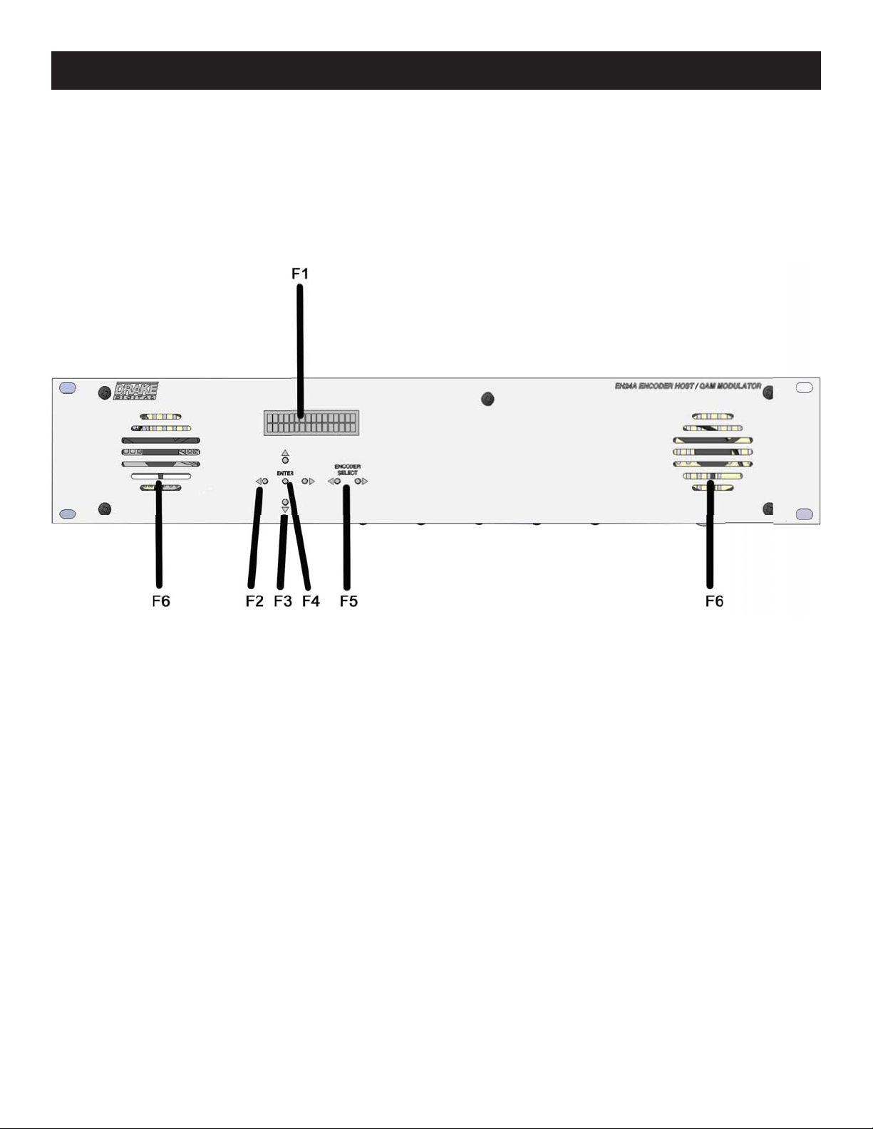
F1, LCD Display - This display presents the selected menu screen and the parameter settings. The backlight in the
display is on when power is applied.
F2, Left and Right Buttons - -- Use the left and right arrow buttons to navigate from screen to screen to view a
parameter setting within a particular program group. These buttons are operational in the view mode or the program
mode. Using only these buttons will not change any parameter setting.
F3, Up and Down Buttons --- Use the up and down arrow buttons to change the value of a viewed parameter setting.
The unit must be in the program mode in order for these buttons to become active for changing a parameter setting. If the
unit is not in the program mode, pressing the Up button will show the version number of the EH24A firmware. Repeatedly
pressing the Down button will toggle between showing the Mbits/S for QAM and the Mbits/S for ASI.
F4, ENTER Button - Use the ENTER button to enter the program mode or to save and load a new setting or
settings after adjustment. Hold for approximately 2 seconds until the bottom line of the display starts to flash to enter
the program mode. After entering the program mode, momentarily pressing the ENTER button again will load and
save any settings that may have been changed using the Up and Down buttons.
F5, Left and Right ENCODER SELECT
the available SDE24/SDE24A Encoders and EH24A settings The selection of the desired parameters for the selected
encoder or EH24A can then be made using the LEFT and RIGHT (F2), UP and DOWN (F3), and ENTER (F4) buttons
F6, Ventilation Fan Vents: These are the intake vents for the two ventilation fans. The exhaust vents are on the
back of the unit. Do not cover any of these vents as overheating may result.
Buttons
- Use the left and right ENCODER SELECT buttons to navigate through
Page 9

Rear Panel Connections 9
REAR PANEL CONNECTIONS
R1, RF OUTPUT - -- This type "F" connector is the high level (+45 to +61 dBmV), 54 to 1002 MHz, output from the EH24A
RF output section.
R2, VIDEO 1 & 2 - These two RCA type connectors color coded yellow provide two separate video inputs to the
SDE24/SDE24A Encoder.
R3, AUDIO 1 & 2 - These four color coded RCA type connectors provide audio Left (white) and Right (red) inputs
to the SDE24/SDE24A Encoder.
R4, This is space available for additional SDE24/SDE24A Encoders which may be installed in the EH24A Encoder Host.
R5, ASI OUTPUT - This BNC type connector provides ASI output of the multiplexed transport streams from selected
encoders.
R6, Cooling Air Vents
R7, Ethernet Port - Connection to a PC or modem for use with remote control / monitoring program or for firmware
upload.
R8, AC Line Cord Socket - -- For connection to the mains AC power source. The removable line cord allows for operation
in various countries. Use an appropriate cord for your needs that has been recognized by a certified safety agency. This unit
is usually supplied with a cord for USA operation on 120 VAC.
The power supply automatically accepts a mains supply from 90 to 264 VAC, 47 to 63 Hz. Power consumption will vary
depending on the number of modules installed but worst case consumption is 70 W.
R9, EAS - This terminal is used to supply the EH24A with a contact closure when the EAS is activated, as determined by
an external EAS controller/receiver. The external EAS controller will supply a contact closure output for connection to the
EH24A EAS and GND terminals. Grounding the EAS screw terminal, through the contact closure in the controller, will signal
the EH24A that an EAS event has occurred. If EAS has been programmed and the EAS encoder installed, the EH24A will
respond appropriately.
Page 10

10
Ethernet Control Interface Configuration
There are two options for the ethernet control interface setup. If your ethernet network has a DHCP server available,
and you would like to use that to configure the IP address of your EH24A, you may enable DHCP on the EH24A. When
the unit's front panel has exited from configuration mode, you can press the button above ENTER twice to view the IP
address that was discovered by DHCP.
If your network does not have a DHCP server, or you choose not to use DHCP for configuration (this is the recommended
configuration, to avoid your EH24A's IP address changing in the future), you must obtain an IP address, subnet mask,
and default gateway from your network administrator. Once you have determined the correct values for your particular
network, set these values from the front panel.
Once the unit has an assigned IP address, you can view and change its settings from a web browser. For instance, if the
unit's IP address were 10.0.0.1, you would load http://10.0.0.1 in your web browser to view and configure your EH24A.
The username and password required to log into the unit are both set from the front panel.
Once the EH24A web server has been loaded from your browser, you should see the login dialog (see Fig. 1). Enter the
username and password (configurable via the front panel interface) and click LOG IN.
Once you are logged in to the EH24A, you will be presented with the status page (see Figure 2). Along the top edge of
the page, there are five tabs listed; each tab allows you to view and configure different parts of the encoder host. The
Status tab gives the overall status of the whole unit, including firmware versions, output bit-rates for all 4 outputs, output
buffer usage, and links to the relevant encoder manuals.
Figure
1:
EH24A Login
Dialog
Page 11

Ethernet Control Interface Configuration (Continued)
11
The Encoders tab allows you to set each encoder's individual parameters. Select an encoder module from the drop-down
menu, and the appropriate setting selections will be displayed.
Figure
2:
EH24A Encoders Tab
Page 12

12
12 Ethernet Control Interface Configuration (Continued)
The Channels tab provides an interface to configure the virtual channel mappings for this encoder host. If PSIP is
enabled, this page will display a screen that looks like Figure 3; for each encoder output, the MPEG program number can
be modified, along with the Major and Minor channel numbers. If one-part virtual channel numbers are desired, the PSIP
Mode must be set to CVCT and the Minor number for each channel should be set to 0.
The Output tab provides an interface to set all modulator output settings for the unit. A screenshot of this tab is shown
in Figure 4. This tab selects the DTA and EAS modes, channel bitrates, QAM settings, and the mapping from encoders to
output channels. For settings like the DTA/EAS options, more options appear as you enable the sub-systems.
Figure
3:
EH24A Channels
Tab
Page 13

13
Ethernet Control Interface Configuration (Continued)
Figure
4:
EH24A Output
Tab
Page 14

14 Ethernet Control Interface Configuration (Continued)
14
Figure
The Firmware Update tab allows you to update all of the firmware on the unit with a single upload (see Figure 5). Once
you have received a new firmware image for the unit, click on the Choose File button and select the provided firmware;
click Upload to initiate the update. After a few minutes, the unit will restart with the new firmware. If a power loss occurs
during update, the unit will recover automatically - -- if the firmware upload was not completed, it may be necessary to
re-initiate the update process once power is restored.
5:
EH24A Firmware Update Tab
Page 15

15
Setup and Programming
Programming and viewing of the various setup and operating parameters is accomplished using the front panel back lit,
two line, sixteen character wide LCD along with the two LEFT and RIGHT ‘ENCODER SELECT’ buttons and the five LEFT,
RIGHT, UP, DOWN and ENTER buttons. The name of the parameter is on the top line of the display and the setting value
is on the bottom line.
To observe a certain parameter setting without intending to change its value, just use the LEFT and RIGHT ENCODER
SELECT buttons and the LEFT and RIGHT arrow buttons to navigate through the menus shown in the software flow
chart on the previous page. The current setting for each parameter is shown on the bottom line of the display. Note that
depending upon certain settings, some screens are not needed and will be skipped.
To make a change in the displayed parameter and its setting and if this is the initial setup, you will want to enter the
‘program’ mode. To do this, press the ENTER button that is located in the center of the four arrow buttons and hold in for
several seconds until the bottom line of the display begins to flash.
After you are in the program mode (bottom line of screen flashing) use the LEFT and RIGHT arrows to navigate among
screens and use the UP and DOWN arrows to change the parameter setting. When ENTER is pressed, the new settings will be
loaded and stored and the unit will exit the ‘program’ mode. You may wish to not press ENTER until you have gone through
all screens and settings and then press ENTER to save and load all changes in one step, OR you can store just one or several
parameters at a time and reenter program mode to set the next. Either method is acceptable.
This section provides additional details regarding the selectable items shown in the ‘program’ mode on the
Software Flow Chart on page 10.
SETUP: EH24A
USER NAME: Variable - -- this sets the username for the ethernet control interface authorization; this field is case-
sensitive
PASSWORD: Variable - -- this sets the password for the ethernet control interface authorization; this field is case-
sensitive
HOST NAME: Variable - -- this sets the display hostname for the ethernet control interface
DHCP: ENABLED, DISABLED - -- this configures the ethernet control interface to use DHCP for its IP configuration settings
when enabled, or to use the static IP configuration that follows when disabled
***(for first time setup, the default USER NAME is "admin" and the default PASSWORD is "EH24")***
IP ADDRESS: Variable - -- this sets the ethernet control interface's static IP address when DHCP is disabled SUBNET
MASK: Variable - -- this sets the ethernet control interface's IP subnet netmask when DHCP is disabled GATEWAY
ADDRESS: Variable --- this sets the default gateway for the ethernet control interface when DHCP is
disabled
OUTPUT MODE: This menu provides a means to determine whether the EH24A output should be QAM and ASI or ASI
output only.
PACKET DELAY: This menu allows the user to determine the packet delay. The choices are 0 to 200 microseconds. A
good default value is usually 50 uS. If pixilation is seen in some programs, the delay may need to be increased. Increase in
small increments as too much delay can cause a buffer overflow -this will be indicated in the front panel LCD.
DTA/EAS
allows for an ASI stream, generated by a PC to be input to the headend’s Master EH24A. This control allows for generating a
transport stream that provides a virtual channel map to the DTAs (Known as SCTE 65 tables), and/or provides code updated
to the DTA’s (in a format known as DSM-CC) so that they can be updated through the QAM channel transport stream. The
choices are DISABLED, MASTER, and SLAVE.
CONTROL:
The DTA control is used when EH24As are used to supply the QAM signals to DTA set top boxes. It
Page 16

16
Setup and Programming (continued)
EAS MODE: EAS Control is provided by 1 of 2 methods:
Method 1: - By using the new SDE24EAS module. This module has only a single composite input instead of the 2 inputs
of a standard SDE24/SDE24A. It is fed by an external EAS Controller source, that then is encoded by both encoders in the
modified SDE24/SDE24A. When EAS is activated, the transport stream generated by the SDE24EAS is routed internally
in the EH24A and replaces the transport streams coming from the other plugged in SDE24/SDE24A's. This way all
MPEG programs coming out of the EH24A have the EAS video and audio on them. Note that when using this method
only 1 SDE24EAS is required per headend, and is placed into the Module 6 slot of the Mas
Method 2: By using the newer digital standard for EAS (known as SCTE 18). In this mode, rather than each MPEG
program being replaced by the EAS video, instead when the EAS is activated, a table is inserted into the transport
stream. This table tells any SCTE 18 capable unit which RF channel to switch to and which MPEG program number
to begin decoding. The receiving unit then switches to that program to display the EAS video and audio. When the
EAS is deactivated, the receiving unit returns to its original channel.
The EAS MODE menu allows the user to select which EAS mode is desired. The choices are DISABLED, MODULE
6, SCTE 18, and MODULE 6 + SCTE 18.
EAS RF CHANNEL: This menu allows the user to determine on which RF channel EAS information will be
outputted. Note that this menu will only appear if DTA/EAS is set to MASTER and EAS MODE is set to enable
SCTE18. The choices are 2 through 158.
ter EH24A.
EAS MODULATION: Note that this menu will only appear if DTA/EAS is set to MASTER and EAS MODE is set to
enable SCTE18. This menu allows the user to determine the type of modulation to be used for the EAS information.
The choices are QAM64B or QAM256B.
EAS MPEG PROGRAM #: Note that this menu will only appear if DTA/EAS is set to MASTER and EAS MODE
is set to enable SCTE18. This menu allows the user to determine on which MPEG program number the EAS
information will appear. The choices are 1 thru 65535.
EAS MAJOR CHANNEL: Note that this menu will only appear if DTA/EAS is set to MASTER and EAS MODE is
set to enable SCTE18. This menu allows the user to select on which major channel the EAS information will appear.
The choices are 1 through 999.
EAS MINOR CHANNEL: Note that this menu will only appear if DTA/ EAS is set to MASTER and EAS MODE
is set to enable SCTE18. This menu allows the user to determine the minor channel number on which the EAS
information will appear. The choices are through 999.
ENCODER 1 THRU 12: These menu items provide the means for selecting the desired output mode of operation
for each of the installed encoders. The available settings are DISABLED, QAM + ASI, ASI, and QAM.
QAM MGT/VCT: This menu item provides a means for the user to select either CVCT or TVCT tables or DISABLED
for QAM operation. TVCT is the typical setting.
QAM MAJOR CHANNEL: The user may use this menu entry to define the QAM major channel number. The
choices are OUTPUT CHANNEL or USER DEFINED using an external PC with Drake Digital Headend Remote
Control Software.
ASI MGT/VCT: This menu item provides a means for the user to select either CVCT or TVCT tables or DISABLED
for ASI operation.
ASI MAJOR CHANNEL: The user may use this menu entry to define the ASI major channel number. The choices
are OUTPUT CHANNEL or USER DEFINED using an external PC with Drake Digital Headend Remote Control
Software.
QAM MODE: This menu allows the user to set the modulation type for the output. Choices range from QAM-
16A through QAM-1024B. 'A' suffixes indicate DVB compliant FEC and the B suffixes indicate DigiCipher II FEC
encoding. Note that the output QAM mode usually must be QAM-256. For CATV systems using DigiCipher II,
select the QAM-256B mode. For DISH Network QAM distribution or other DVB systems using DVB set tops,
choose the QAM-256A mode.
Page 17

Setup and Programming (continued)
17
GRAY ENCODING: This menu is only available when QAM modes QAM-16A through QAM-1024A, are selected.
The choices are DVB and DAVIC. Gray Encoding is normally not used for video data.
QAM SYMRATE: Preset or Manual: If PRESET is selected, the symbol rate will be automatically set to the
‘normal’ rate based on the QAM mode that is selected and assuming a 6 MHz wide QAM channel. If MANUAL is
selected, pressing the right or left arrow buttons will allow selection of symrates from 1.000 thru 7.000 MSym/Sec.
QAM SYMRATE: This menu item only appears of ‘Manual’ is selected in the previously described menu item. It
allows selection of the output QAM baudrate or symbol rate. Set as required by the set top box.
INTERLEAVER: This menu item only appears if QAM-64B, QAM- 256B, or QAM-1024B is selected and provides
the means to set the QAM modulator interleaver. Choose among the available selections based upon your system
/ set top box requirements. For typical 256-QAM DigiCipher II CATV systems, I128, J1 is the most commonly
used interleave setting but many other choices are available. This menu does not appear in the adjust mode if
the QAM mode is A (DVB) as there is only one choice in the DVB standard.
OUTPUT FORMAT: For normal operation, select NORMAL. For system level set up, choose CW to provide a
CW carrier at the center frequency of the output channel for use in leveling a system when a QAM power meter
is not available. To disable all RF output, select STANDBY. In the CW mode, the CW carrier can be measured
on a spectrum analyzer without a need to apply a bandwidth correction or it can be measured with an analog
meter tuned to channel center. The CW power measured will equal the channel QAM power when the modulator
is returned to NORMAL output mode. Usually QAM signals are set 5 dB to 10 dB below analog NTSC channels
when balancing a sy
stem.
PRBS menu entries are used for testing purposes only and should normally not be selected by the user.
OUTPUT CHANMAP, OUTPUT CHANNEL: Select the desired EIA CATV channel output using these two menus.
RF LEVEL: Select the desired RF output signal level. The available range is between +45 dBmV and +56 dBmV,
selectable in 0.5 dB steps. The output accuracy is ± 1 dB.
SETUP: ENDODER xx
ENCODER SELECT: The LEFT and RIGHT buttons allow the user to scroll through the encoder numbers for each encoder
installed in the EH24A as well as the EH24A itself. Use the LEFT and RIGHT buttons to select the encoder to be programmed.
VIDEO: This menu entry allows the user to select between SVIDEO and COMPOSITE video input for each selected
encoder.
FORMAT: Either MPEG2 or MPEG4 H.264 may be selected as the output format for the selected encoder using
this menu item. Encoder 2 on a given SDE24/SDE24A has no option. It is forced to MPEG2.
BITRATE: This menu item allows the user to select the bitrate. The choices are from 1 to 8 Mbits per second.
INPUT: This menu allows the user to select between the NTSC or PAL video formats.
RESOLUTION: The resolution of the video output of each encoder may be selected from this menu item. The
choices range from 720 x 480 thru 353 x 240 as shown on the software flow chart on page 10.
BRIGHTNESS, CONTRAST, SATURATION and HUE: These menu items allow the user to assign each of these
parameters of the output video values from 0 to 255.
AUDIO ENCODER: The SDE24/SDE24A includes audio encoders for Dolby Digital Stereo commercial encoding or MPEG1
Layer 2 audio encoding (MP2). In the USA, the majority of applications will use Dolby Digital (referred to within EH24A
settings as " AC3") but if your network is using Annex A (DVB) set top boxes, they may require the MPEG audio selection.
Some TVs and set top boxes will decode either mode but be sure to set the encoder to the mode used by other programming on your system to insure complete compatibility. The AUDIO ENCODE(R) menu allows you to select either AC3 or MP2.
Use the up/dn arrow keys to toggle between the two settings.
MAX AUDIO IN: This menu entry allows the user to set the maximum audio input which may be input to the selected
encoder. The choices are 1 Vrms or 2 Vrms.
AUDIO GAIN: The audio output level can be chosen from this menu item by selection of the appropriate gain. The
values range from + 15 dB to - 15 dB. Audio output can also be completely eliminated using the ‘MUTE’ selection.
Page 18

18 Operating Instructions
OPERATING INSTRUCTIONS – FROM THE FRONT PANEL
1) Connect video and audio inputs to desired encoder modules. Note, as viewed from the rear, the number 1
program will be on the left, the one closest to the RF output connector. The number 2 program will be the next
input to the right.
2) Connect the outputs as desired.
3) Plug the EH24A into AC power. Allow 30 to 90 seconds for boot-up.
4) From the front panel, use the ENCODER SELECT buttons to choose among EH24A settings and settings for each
encoder. Use the ENTER button to enter program mode and to save settings in memory. Use left and right arrows to
select a parameter and then use the up or down arrows to change its value. Parameters values can only be changed
when the unit is in the program mode as indicated by slow flashing of the front panel display. To enter program mode,
press the ENTER key and hold for 2 to 3 seconds.
5) Press ENTER for 3 seconds to enter program mode.
6) Repeatedly press the ENCODER SELECT right or left arrow until the display shows: SETUP EH24A.
7) Repeatedly press the left or right arrows (on either side of the enter button) until the display reads ENCODER1.
Press up or down arrows to select which output or both outputs that this encoder is to output to. Then press the right
arrow once to advance to ENCODER 2. Choose output for this one. Proceed in this manner until all encoders have
been directed to the desired outputs. ENCODERs 1 and 2 will be the first module, 3 and 4 the second module, 11
and 12 the sixth module, etc. If an encoder is installed but you don’t plan to use it, be sure to choose the DISABLED
choice for any such encoders.
8) Press the right arrow again after setting the 12th encoder. This should produce the QAM MGT/VCT screen.
Usually select TVCT by using up or down arrows.
9) Press right arrow again and observe the QAM MODE screen. Use up or down arrows to select QAM mode. For
example, QAM-256B would select 256 QAM with annex B FEC (DigiCipher FEC).
10) Press right arrow again and observe QAM SYMRATE. Set to PRESET. PRESET will be 5.057 MS/S for QAM-
64B or 5.3606 MS/S for QAM-256B, etc. If a nonstandard rate is desired, choose MANUAL.
11) Press right arrow again and observe INTERLEAVER. Select I128,J1 unless you have a special requirement.
12) Press right arrow again and move to the OUTPUT FORMAT. Choose NORMAL. For testing/level setup - --
temporarily choose CW to produce a CW carrier in the center of the channel. Other PRBS choices are for testing
only.
13) Press right arrow again and observe OUTPUT CHANMAP. Select the desired plan, usually CATV.
14) Press right arrow and observe OUTPUT CHANNEL. Select desired channel. The RF channel number being set
will be used as the major channel number in the output stream.
15) Press right arrow and observe RF OUT. Choose desired RF out level.
16) Press right arrow and observe UNIT ID. If not using Ethernet remote control, choose 0.
17) Press the right arrow and observe Ethernet BAUDRATE. Set to 4800 unless otherwise directed.
18) Press the right arrow and observe that you are back to the ENCODER 1 screen.
Page 19

19
Operating Instructions (continued)
At this point, you can press ENTER to store all of the choices on page 14. Actually, you could store after setting
just one item or after two items, etc. But once you store a parameter(s), you must renter the program mode to
make any additional adjustments.
All of these settings can be set using a PC connected via the Ethernet port or through the Ethernet connection via the
DRAKE model SCTeci Control unit.
Having completed EH24A settings on page 14, you are now ready to setup each individual encoder.
19) Press ENTER for 3 seconds to enter program mode. Observe flashing display.
20) Use left or right ENCODER SELECT buttons to choose one of the installed encoders.
21) To set the encoder to typical default settings, press the up arrow, down arrow, and ENTER all at the same time.
Hold the three buttons in for several seconds and release.
22) If any of the encoder settings need changed from the default values, re-enter program mode and adjust each
encoder parameter as required.
23) Repeat from step 19 for each enabled encoder.
24) Press ENTER to store any unsaved changes.
Page 20

20 Additional Information
DISABLED
SCTE 18
SDE24/SDE24A or empty
SDE24/SDE24A or empty
DISABLED
MODULE 6
SDE24EAS
SDE24/SDE24A or empty
DISABLED
MODULE 6 + SCTE 18
SDE24EAS
SDE24/SDE24A or empty
ENABLED
DISABLED or SCTE 18
ASII
SDE24/SDE24A or empty
ENABLED
MODULE 6
SDE24EAS
ASII
ENABLED MODULE 6 + SCTE 18
SDE24EAS
ASII
ADDITIONAL INFORMATION
STANDBY MODE
The EH24A has a standby output mode which turns off the RF output. This can be used when it is desirable to temporarily disable the
output without unplugging the AC line cord. Select DISABLED in the ‘QAM MGT/VCT’ menu. Individual encoders can be disabled or
enabled when in the QAM mode from the ‘ENCODER xx’ menu.
OVER TEMPERATURE SENSOR
Temperature monitoring is built into this product. If inadequate ventilation is provided, overheating may occur. If this condition
is detected, the default LCD message will change to OVER TEMP. If this occurs, the problem should be corrected as soon
as possible. The unit will remain operational but the ventilation must be restored to prevent premature part failures due to
overheating.
STATUS DISPLAYS
When the units are not in the program mode, status displays are shown. The default display shows the QAM OUTPUT Mbits/S. When
the UP button is pressed, the version number of the EH24A firmware is displayed. The DOWN button toggles the display between
QAM OUTPUT Mbits/S and ASI OUTPUT Mbits/S.
REMOTE CONTROL AND MONITORING
The EH24A may be used with the 'Drake Digital Headend Remote Control Software' program to allow remote monitoring or control.
Only version 3.0 or newer version of the software is compatible with the EH24A. Connect the Ethernet cable coming from the PC or
modem to the Ethernet IN port rear panel connector. Assign a UNIT ID (1 to 63) to use the remote program. Leave at, or set to, 0 if no
remote access is desired.
EAS CONSIDERATIONS
Any headend using EAS and/or DTAs that includes more than one EH24A must be setup with one EH24A being the Master and all
other EH24As being Slaves.
These setups require different configurations of the EH24A with the SDE24EAS and ASII plug in modules.
-If set as a Slave Unit, Module 6 must always be an ASII module.
-If set as the Master unit, then there are 4 possible configurations for what needs to be plugged into the Module 6
and the Module 5 slots.
DTA MODE
EAS MODE
Module 6 Plug-in
Module 5 Plug-in
As shown above, if DTA MODE is ENABLED, then an ASII module must be present in the Master EH24A to receive the ASI stream from
the PC. Whether it is plugged into Module 5 or Module 6 slot depends on whether the SDE24EAS is also required in the system or not.
All units at the headend are then daisy-chained through ASI connections.
The Master unit’s ASI OUTPUT connector goes to the ASI INPUT connector of the ASII module in the first Slave unit.
The ASI LOOP output connector of the ASII module in the first Slave unit goes to the ASI INPUT connector of the ASI
module in the next slave unit.
These ASI LOOPs continue through all EH24As at the headend.
There can be standard SDE24/SDE24A's in some or all of the remaining slots of the Master EH24A. If they are wanted to be sent out on the
ASI output of the Master EH24A can be picked up from the ASI LOOP output connector of the ASII module of the last Slave unit in the
chain.
VERY
IMPORTANT:
When the SDE24EAS is used in slot 6, both encoders in the SDE24EAS must be set to the lowest
encoding bitrate of any other SDE24/SDE24A in the entire system. This is the only way to make sure that when its stream replaces
the original streams that it will still fit into all the QAM channels.
Page 21

CABLE
BIAJN
--------
CTA
Nurnellli :
CUJIV
8'1
en1
2
3
4
5
IS
95
'96
91
98
gg
14
15
16
11
18
19
20
21
22
7
8
9
10
H
12
13
23
24
25
.26
27
28
29
10
31
JZ
13
:l4
35
16
37
38
.39
40
TV C
HANt.IEL
Freq
l!.lEIJlC)
m
MH.tz
57
6J
69
79
8.5
9'3
gg
10
5
111
117
l23
1
29
13
5
1
41
147
153
1
59
165
171
H
7
183
189
195
20
1
207
213
219
225
23
1
237
243
249
.255
26
1
26
7
.273
279
:28
5
.29
1
29
7
303
309
31
5
121
af!'net
MH
001
87
3
879
8:
85
8Q1
891
903
90
9
915
921
927
9JJ
93
0
945
951
957
003
959
975
981
91H
9
93
999
O
lz.
f
CATV
TABLE
I'
--------
CABLE T'!J C
C
/J<:JmH/
Number
EIAINCTA
Ntuneric
E
quiv,alent in
HIANNELS
c.emer
C
fr;;mJJel
FrequenG)
Mli-t z
41
42
43
44
45
46
47
48
49
50
51
52
53
54 40
ss
56
57
58
5!)
60
6·1
62
63
Ei!i
BG
67
68
69
70
1'1
72
73
14
75
76
17
78
79 55
80
81
82
83
B4
85
"l21
331
JJ9
.J.4
351
351
363
:369
37
331
3B7
39J
399
411
417
423
429
43
44.1
44
453
4'59
465
471
477
4
489
495
501
07
'5B
519
!525
'53
537
!543
54
561
"JGI
573
!579
!535
591
83
1:
CATV
nr
'
5
5
5
5
7
1
9
5
Channel
Ff'llQoonc.y
in
85 :597
87
88
89
91
91
93
94
100
101
102
10J
104 67
105
106 687
101
100
109
1
"11
112
1 13
1"14
115
116
1
"11
118
119 765
132
13)
134
135
003
009
615
639
651
657
66l
66
681
693
eg
705
723
729
135
74
75
7
843
855
001
Frequencies 21
---------
CABLE l\1'
CIJ
iil
Number Ch
trm
,-1
CHAJNHELli
C
HA.'HCTA
Numeric
quivent
'36
Frequency
in
07
138
'39
uo
141
'42
14."3
144
'
45
146
147
'i 48
ug
1
5(]
51
152
15,)
54
t
5
15S
57
t58
t.'VHIU
MHz.
1
5
9
5
g
'
1
l
59
9
Page 22

22
Broadcast
1V Channel
Frequencies
• ••
TABLE 2:
VHFBROA.OCAST CHAI'BlELS
Ch
....
lltJ..J
Numb<lt FtOfJUOII
2
3
Conlw of
57
G3
6
'
7
6
10
II
12
13
177
18
189
195
201
2
213
ChMJn..J
'
9
l
07
H'
EX:
TV
1"5
1C
17
1
8
2
1
22
2
3
31
3
2
33
51
52
53
61
62
63
67
G8
69
CA:...t«
of
Fro ucn
ChM nW
<7
3
479
485
<91
497
Hz
515
521
7
52
575
581
5
67
6
35
G
41
647
671
677
695
1
70
707
7
55
78
1
767
76
5
79
1
797
80
3
Page 23

SERVICE INFORMATION
ESHe2r4v4icEeNC/OIfDYEoRuHONSeTeSdERToIES
Call For Help
23
A Return Material Authorization (RMA) Number is required on ALL PRODUCT RETURNS (regardless of wheth er the product is being returned for repair or for credit). Product that is received at the factory without an RMA
Number will be returned to the Sender, unopened.
RMA Numbers must be used when returning product for credit or repair. Use of RMA Numbers will ensure
efficient processing. When needing to return your product to R.L. Drake Holdings, LLC., please follow these
simple steps listed below (in the order that they appear).
SERVICE REPAIRS ONLY CREDIT RETURNS ONLY
1. Contact R.L. Drake Holdings, LLC.’s Service Department 1. Contact R.L. Drake Holdings, LLC.’s Service Department
in one of three ways: in one of three ways:
A. Phone: 937-746-6990 A. Phone: 937-746-6990
B. Email: servicehelp@rldrake.com B. Email: servicehelp@rldrake.com
2. Request from Drake Service a copy of the Product Return 2. Request from Drake Service a copy of the Product Return
3. Complete the Product Return Authorization Form fully. 3. Complete the Product Return Authorization Form fully.
4. Return the completed Product Return Authorization Form 4. Return the completed Product Return Authorization Form
5. After completing Steps 1 through 4, an RMA Number will 5. After completing Steps 1 through 4, an RMA Number will
6. Securely pack the product and mark the box with your RMA 6. Securely pack the product in its original undamaged box
C. Fax: 937-806-1510 C. Fax: 937-806-1510
Authorization Form. Authorization Form.
to the Drake Service Department using one of the contact to the Drake Service Department using one of the contact
methods listed in Step 1. methods listed in Step 1.
be assigned to you. be assigned to you.
Number. If shipping multiple boxes, all boxes must be mark- (returning the product without its original packaging in good,
ed with the RMA Number. Place the RMA Number near the new condition may cause the incursion of additional fees).
return address in large, bold print (approx. 2” in height). Pack this box within another shipping container or box.
Mark the shipping box or container with your RMA Number.
Place the RMA Number near the return address in large,
bold print (approx. 2” in height).
7. Ship your “SERVICE REPAIR ONLY” return to: 7. Ship your “CREDIT RETURNS ONLY” return to:
R.L. Drake Holdings, LLC. R.L. Drake Holdings, LLC.
Attn: Product Service Returns Attn: Product Credit Returns
9900 Springboro Pike One Jake Brown Road
Miamisburg, OH 45342 Old Bridge, NJ 08857
*NOTE: All Credit Returns are subject to a 15% Restock Fee
*NOTE: All shipments are to be PRE-PAID by the sender. NO COD’s will be accepted.
IF YOU NEED TECHNICAL HELP
Call our Customer Service/Technical Support line at +1 (937) 746-6990 between 8:00 A.M. and 4:00 P.M. Eastern Standard Time, weekdays. Please have the unit’s serial number available. We will also need to know the specifics of any
other equipment connected to the unit. When calling, please have the unit up and running, near the phone if possible.
Our technician(s) will likely ask certain questions to aid in diagnosis of the problem. Also, have a voltmeter handy, if at all
possible.
DRAKE also provides technical assis tanc e b y Email: servicehelp@rldrake.com
Many of the products that are sent to us for repair are in perfect working order when we receive them. For these units,
there is a standard checkout fee that will be charged. Please perform whatever steps are applicable from the product’s Instruction Manual before calling or writ ing - this could save unnecessary phone charges. Please do not return the product
without calling Drake Service and following the steps above first; it is preferred to help troubleshoot the problem over the
phone (or by Email) first, saving you both time and money.
Fax: (937) 806-1510.
Page 24

24
LIMITED WARRANTY
Seller will at its sole opti on, either repair or replac e (with a new or factory rec onditioned product, as Seller m ay determine) any product m anufactured or
sold (or in the case of software, licensed) by Seller which is defective in materials or workmanship or fails to meet the applicable specifications that are
in effect on the date of shipment or such other spec ifications as may have been expressly agreed upo n in writi ng: (i) for a period of t hree (3) years from
the date of original purchase for all stock hardware products (other than those specifically referenc ed herein below having a shorter warranty period); (ii)
for a period of one (1) year from the date of original purchase, with respect to all MegaPort™, IPTV products, test equipment and fiber optics receivers,
transmitters, couplers and integrated receiver/ distribution amplif iers; (iii) for a period of one (1) year from the date of origi nal purchase (or such shorter
period of time as may be set forth in the license agreement specific to the particular software being licensed from Seller) with respect to all software products licensed from Seller (other than Core Product Software) that is (a) developed for a specific function or application, (b) complimentary to and does not
function without the Core Product Software, and (c) listed with a specific model number and stock number in Seller’s Price List (“Non-Core Software”); (iv)
for a period of ninety (90) days from the date of original purchase, with respect to non-serialized products and accessories, such as parts, sub-assemblies,
splitters and all other products sold by Seller (other than Core Product Software and Refurbished/Closeout Products ) not other wise referred to i n clauses
(i) through (iii) above. The warranty period for computer programs in machine-readable form included in a hardware product, which are essential for the
functionality thereof as specifically stated in the published product specificat ions (“Core Product Software”) will be coincident with the warranty period of
the applicable hardware product within which such Core Product Software is installed.
Software patches, bug fixes, updates or workarounds do not extend the original warranty period of any Core Product Software or Non-Core Software.
Notwithstanding anything herein to the contrary,
(i) Seller’s sole obligation for software that when properly installed and used does not substantially c onform to the publis hed specificat i ons in effect when
the software is first shipped by Seller, is to use commercially reasonable efforts to c orrect any reproducible material non-conformity (as determined by
Seller in its sole discretion) by providing the customer with: (a) telephone or e-mail access to report non-conformanc e so t hat S eller can verif y reproduc ibility, (b) a software patch or bug fix, if available or a workaround to bypass t he issue if available, and (c) where applicable, replac ement or damaged or
defective external media, such as CD-ROM disk, on which the software was originally delivered;
(ii) Seller does not warrant that the us e of any software will be uninterrupted, error -free, free of sec urity vulnerabiliti es or that the s oftware will meet t he
customer’s particular requirem ents; and the cust omer’s sole and exclusive remedy for breach of this warranty is, at Seller’s option, to receive (a) suitably
modified software, or part thereof, or (b) comparable replacement software or part thereof;
(iii) Seller retains all right, title and interest in and to and ownership of all software (includi ng all Core Product Software and Non-Core Software) including
any and all enhancements, modifications and updates to the same; and
(iv) in some cases, the warranty on certain proprietary sub -assembly modules manufactured by third-party vendors and contained in Seller’s products,
third party software installed in certain of Seller’s products, and on certain private–label products manufactured by third-parties for resale by Seller, will
be of shorter duration or otherwise more limited than the standard Seller limited warranty. In such cases, Seller’s warranty with respect to such third-party
proprietary sub-assembly modules, third-part y software and private-label products will be limited to the duration and other terms of such third-party vendor’s warranty, if any. In addi tion, cert ain products , t hat are not m anufactured by S eller, but are resold by Seller, may carry the original OE M warranty fo r
such products, if any. The limited warranty set forth above does not apply to any product sold by Seller, which at the time of sale constituted a Refurbished/
Closeout Product, the limited warranty for which is provided in the following paragraph.
Seller will at its sole option, either repair or replace (with a new or factory-reconditioned product, as Seller may determine) any product sold by Seller which
at the time of sale constituted a ref urbished or clos eout item (“Refurbished/ Closeout Product”), which i s defective in m ateri als or workmanship or f ails t o
meet the applicable specifications that are in eff ect on the date of shi pment of that product or f ails to meet such ot her specifications as may have been
expressly agreed upon in writing between the parties, for a period of ninety (90) days from the date of original purchase. Notwithstanding the foregoing, in
some cases the warranty on certain propriet ary sub-as sembly modules manuf act ured by third-party vendors and contained i n Sell er products, third party
software installed in certain of Seller’s products, and on certain private–label products m anufactured by third-part ies f or resal e by Seller will be of short er
duration or otherwise more limited than Seller limited warranty for Refurbished/Closeout Products. In such cases, Seller’s warranty for Refurbished/Closeout Products constituting such third party proprietary sub-assembly modules, third party software, and private-label products will be limited to the duration
and other terms of such third-party vendor’s warranty, if any. In addition, notwithstanding the foregoing, (i) certain Refurbished/Closeout Products that are
not manufactured (but are resold) by Seller, may carry the original OEM warranty for such products, if any, which may be longer or shorter than Seller’s
limited warranty for Refurbished/Closeout Products. All sales of Refurbished/Closeout Products are final.
To obtain service under this warranty, the defective product, together with a copy of the sales receipt, serial number if applicable, or other satisfactory proof
of purchase and a brief description of the defect, must be shipped freight prepaid to Seller at the following address: One Jake Brown Road, Old Bri dge,
New Jersey 08857.
This warranty does not cover failure of performance or damage resulting from (i) use or installation other than in strict accordance with manufacturer’s written instructions, (ii) disassembly or repair by someone other than the manufacturer or a manufacturer-authorized repair center, (iii) misuse, misapplication
or abuse, (iv) alteration, (v) exposure t o unusual physical or electrical s t ress , abuse or accident or forces or exposure beyond normal use within specif i ed
operational or environmental parameters set forth in applic able product specifi cations, (vi) lack of reasonable care or (vii ) wind, ice, snow, rain, lightning,
or any other weather conditions or acts of God.
OTHER THAN THE WARRANTIES SET FORTH ABOVE, SELLER MAKES NO OTHER WARRANTIES OR REPRESENTATIONS OF AN Y KIND,
EXPRESS OR IMPLIED, AS TO THE CONDITION, DESCRIPTION, FITNESS FOR A PARTICULAR PURPOSE, MERCHANTABILITY, OR AS TO ANY
OTHER MATTER, AND SUCH WARRANTIES SET FORTH ABOVE SUPERSEDE ANY ORAL OR WRITTEN WARRANTIES OR REPRESENTATIONS
MADE OR IMPLIED BY SELLER OR BY ANY OF SELLER’S EMPLOYEES OR REPRESENTATIVES, OR IN ANY OF SELLER’S BROCHURES
MANUALS, CATALOGS, LITERATURE OR OTHER MATERIALS. IN ALL CASES, BUYER’S SOLE AND EXCLUSIVE REMEDY AND SELLER’S SOLE
OBLIGATION FOR ANY BREACH OF THE WARRANTIES CONTAINED HEREIN SHALL BE LIMITED TO THE REPAIR OR REPLACEMENT OF THE
DEFECTIVE PRODUCT F.O.B. SHIPPING POINT, AS SELLER IN ITS SOLE DISCRETION SHALL DETERMINE. SELLER SHALL IN NO EVENT AND
UNDER NO CIRCUMSTANCES BE LIABLE OR RESPONSIBLE FOR ANY CONSEQUENTIAL, INDIRECT, INCIDENTAL, PUNITIVE, DIRECT OR SPECI AL D AM AGE S BASED UPON BREACH OF WARRANTY, BREACH OF CONTRACT, NEGLIGENCE, STRICT TORT LIABILITY OR OTHERWISE
OR ANY OTHER LEGAL THEORY, ARISING DIRECTLY OR INDIRECTLY FROM THE SALE, USE, INSTALLATION OR FAILURE OF ANY PRODUCT
ACQUIRED BY BUYER FROM SELLER.
All claims for shortages, defects, and non-conforming goods must be made by the customer in writing within five (5) days of receipt of merchandise, which
writing shall state with particularity all material facts concerning the claim then known to the cust omer. Upon any such claim, the customer shall hold the
goods complained of intact and duly protected, for a period of up to sixty (60) days. Upon the request of Seller, the customer shall ship such allegedly nonconforming or defective goods, freight prepaid to Seller for examination by Seller’s inspection department and verification of the defect. Seller, at its option,
will either repair, replace or issue a credit for products determined to be defective. Seller’s liability and responsibility for defective products is specifically limited to the defective item or to credit towards the original billing. All such replacements by Seller shall be made free of charge f.o.b. the delivery point called
for in the original order. Products for which replacem ent has been made under the provisions of t hi s clause shall become the property of Seller. Under no
circumstances are products to be returned t o Seller without Seller’s prior written authorization. Sell er reserves the right to scrap any unaut hori zed returns
on a no-credit basis. Any actions for breach of a contract of sale between Seller and a customer must be commenced by the customer within thirteen (13)
months after the cause of action has accrued. A copy of Seller’s standard terms and conditions of sale, including the limited warranty, is available
Seller upon request. Copies of the limit ed warranties covering third-party proprietary sub-assembly modules and private-label products manufact ured by
third-parties may also be available from Seller on request. (Rev 0713)
Warranty
EH244 ENCODER HOST SERIES
from
Page 25

Page 26

SALES:
937.746.4556
800.777.8876
FAX:
937.806.1510
R.L. DRAKE HOLDINGS, LLC
9900 SPRINGBORO PIKE
MIAMISBURG, OH 45342 USA
sales@rldrake.com
SERVICE: 937.746.6990
FAX: 937.806.1510
servicehelp@rldrake.com
www.rldrake.com
 Loading...