

Page 1
DUC864A
Digital Up-Converter
INSTRUCTION MANUAL
DUC864A
UP
RF LEVEL
DN
UP
CH
DN
+100
ENTER
Model Item # Description
DUC864A 1002387A Digital Up-Converter
937-746-4556
www.rldrake.com
© 2015 R.L. Drake Holdings, LLC.
Rev: 041715 / 651239900A
Page 2

Caution Statements
DSE 2 PLUS | 2
Instruction Manual
Rev: 20140
Table of Contents
IMPORTANT SAFETY INSTRUCTIONS ...................................................................................................................................................... 2
SPECIFICATIONS ............................................................................................................................................................................................ 4
GENERAL DESCRIPTION .............................................................................................................................................................................. 6
FEATURES ........................................................................................................................................................................................................ 6
INSTALLATION AND MOUNTING .............................................................................................................................................................. 6
REAR PANEL CONNECTIONS ..................................................................................................................................................................... 7
ETHERNET ACCESS ....................................................................................................................................................................................... 8
SETUP AND PROGRAMMING ................................................................................................................................................................... 10
FIRMWARE UPDATE .................................................................................................................................................................................... 15
SERVICE / IF YOU NEED TO CALL FOR HELP ........................................................................................................................................ 18
WARRANTY .............................................................................................................................................................................................................. 19
DSE 2 PLUS | 3
Instruction Manual
product. Any mounting of the product should follow the manufacturer's instructions, and should use a mounting accessory recommended by the
manufacturer.
9.
A product and cart combination should be moved with care. Quick stops, excessive force, and uneven surfaces may cause the product and cart combination
to overturn.
10.
Ventilation: Slots and openings in the cabinet are provided for ventilation and to ensure reliable operation of the product and to protect it from overheating,
and these openings must not be blocked or covered. The openings should never be blocked by placing the product on a bed, sofa, rug, or similar
surface. This product should not be placed i n a built-in installation such as bookcase or rack unless proper ventilation is provided or the manufacturer's
instructions have been adhered to.
11.
Power Sources: This product should be operated only from the type of power source indicated on the marking label. If you are not sure of the type of power
supplied to your home, consult your product dealer or local power compan y. For products intended to operate from battery power, or other sources, refer to the
product's operating instructions.
12.
Grounding or Polarization: This product may be equipped with a polarized alternating-current line plug (a plug having one blade wider than the
other). This plug will fit into the power outlet only one way. This is a safety feature. If you are unable to
insert the plug fully into the outlet, try reversing
the plug. If the plug should still fail to fit, contact your electrician to replace your obsolete outlet. Do not defeat the safety purpose of the polarized
plug. Alternate Warnings – If this product is equipped with a three-wire grounding- type plug, a plug having a third (grounding) pin, the plug will only fit
into a grounding-type power outlet. This is a safety feature. If you are unable to insert the plug into the outlet, contact your electrician to replace your
obsolete outlet. Do not defeat the safety purpose of the grounding-type plug.
DSE 2 PLUS | 2
Instruction Manual
Rev: 20140
Table of Contents
IMPORTANT SAFETY INSTRUCTIONS ...................................................................................................................................................... 2
SPECIFICATIONS ............................................................................................................................................................................................ 4
GENERAL DESCRIPTION .............................................................................................................................................................................. 6
FEATURES ........................................................................................................................................................................................................ 6
INSTALLATION AND MOUNTING .............................................................................................................................................................. 6
REAR PANEL CONNECTIONS ..................................................................................................................................................................... 7
ETHERNET ACCESS ....................................................................................................................................................................................... 8
SETUP AND PROGRAMMING ................................................................................................................................................................... 10
FIRMWARE UPDATE .................................................................................................................................................................................... 15
SERVICE / IF YOU NEED TO CALL FOR HELP ........................................................................................................................................ 18
WARRANTY .............................................................................................................................................................................................................. 19
Caution Statements:
WARNING:
TO PREVENT FIRE OR ELECTRICAL
SHOCK, DO NOT EXPOSE TO RAIN
OR MOISTURE.
A product and cart combination should be moved
with care.
Quick stops, excessive force and uneven surfaces may
cause the product and cart combination to overturn.
The lightning flash with arrow head symbol, within an
equilateral
triangle, is intended to alert the user to
the presence of uninsulated "dangerous voltage"
within the product's enclosure
that may be of
sufficient magnitude to constitute a risk of electric
shock to persons.
The exclamation point within an equilateral triangle
is intended to alert the user to the presence of
important operating and maintenance (servicing)
instructions in the literature
accompanying the
product.
WARNING: THE SOCKET-OUTLET SHALL BE INSTALLED NEAR THE EQUIPMENT AND SHALL BE EASILY ACCESSIBLE.
WARNING: TO REDUCE THE RISK OF FIRE OR
ELECTRIC SHOCK, DO NOT EXPOSE THIS PRODUCT TO RAIN OR
MOISTURE. DO NOT OPEN THE CABINE T, REFER SERVICING TO QUALIFIED PERSONNEL ONLY.
CAUTION: TO PREVENT ELECTRIC SHOCK, DO NOT USE THIS (POLARIZED) PLUG WITH AN EXTENSION CORD
RECEPTACLE OR OTHER OUTLET UNLESS THE BLADES CAN BE FULLY INSERTED TO PREVENT BLADE
EXPOSURE.
ATTENTION: POUR PREVENIR LES CHOCS ELECTRIQUE S, N E PAS UTILISER CETTE FICHE POLARISEE AVEC UN
PROLONGATEUR, UNE PRISE DE COURANT OU UNE AUTRE SORTIE DE COURANT, SAUF SI LES LAMES
PEUVENT ETRE INSEREES A FOND SANS EN LAISSER AUCUNE PA RTIE A DECOUVER T.
Important Safety Instructions:
1.
Read Instructions: All the safety and operating instructions should be read before the product is operated.
2.
Retain Instructions: The safety and operating instructions should be retained for future reference.
3.
Heed Warnings: All warnings on the product and in the operating instructions should be adhered to.
4.
Follow Instructions: All operating and use instructions should be followed.
5.
Cleaning: Unplug this product from the wall outlet before cleaning. Do not use liquid cleaners or aerosol cleansers. Use a damp cloth for cleaning.
6.
Attachments: Do not use attachments that are not recommended by the product manufacturer as they may cause hazards.
7.
Water and Moisture: Do not use this product near water—for example, near a bathtub, wash bowl, kitchen sink or laundry tub; in a wet basement;
or near a swimming pool; and the like.
8.
Accessories: Do not place this product on an unstable cart, stand, tripod, bracket, or table. The product may fall, causing serious injury to a child or
adult, and serious damage to the product. Use only with a cart, stand, tripod, bracket, or table recommended by the manufacturer, or sold with the
Caution Statements:
A product and cart combination should be moved
WARNING:
SHOCK, DO NOT EXPOSE TO RAIN
TO PREVENT FIRE OR ELECTRICAL
OR MOISTURE.
with care.
Quick stops, excessive force and uneven surfaces may
cause the product and cart combination to overturn.
The lightning flash with arrow head symbol, within an
equilateral
the presence of uninsulated "dangerous voltage"
within the product's enclosure
sufficient magnitude to constitute a risk of electric
shock to persons.
The exclamation point within an equilateral triangle
is intended to alert the user to the presence of
important operating and maintenance (servicing)
instructions in the literature
product.
triangle, is intended to alert the user to
accompanying the
that may be of
WARNING: THE SOCKET-OUTLET SHALL BE INSTALLED NEAR THE EQUIPMENT AND SHALL BE EASILY A CCESSIBLE.
WARNING: TO REDUCE THE RISK OF FIRE OR ELECTRIC SHOCK, DO NOT EXPOSE THIS PRODUCT TO RAIN OR
MOISTURE. DO NOT OPEN THE CABINE T, REFER SERVICING TO QUALIFIED PERSONNEL ONL Y.
CAUTION: TO PREVENT ELECTRIC SHOCK, DO NOT USE THIS (POLARIZED) PLUG WITH AN EXTENSION CORD
RECEPTACLE OR OTHER OUTLET UNLESS THE BLADES CAN BE FULLY INSERTED TO PREVENT BLADE
EXPOSURE.
ATTENTION: POUR PREVENIR LES CHOCS ELECTRIQUE S, N E PAS UTILISER CETTE FICHE POLARISEE AVEC UN
PROLONGATEUR, UNE PRIS
E DE COURANT OU UNE AUTRE SORTIE DE COURANT, SAUF SI LES LAMES
PEUVENT ETRE INSEREES A FOND SANS EN LAISSER AUCUNE PA RTIE A DECOUVER T.
Important Safety Instructions
2
937.746.4556 | www.rldrake.com
Page 3

Safety Instructions continued...
DSE 2 PLUS | 3
Instruction Manual
product. Any mounting of the product should follow the manufacturer's instructions, and should use a mounting accessory recommended by the
manufacturer.
9.
A product and cart combination should be moved with care. Quick stops, excessive force, and uneven surfaces may cause the product and cart combination
to overturn.
10.
Ventilation: Slots and openings in the cabinet are provided for ventilation and to ensure reliable operation of the product and to protect it from overheating,
and these openings must not be blocked or covered. The openings should never be blocked by placing the product on a bed, sofa, rug, or similar
surface. This product should not be placed i n a built-in installation such as bookcase or rack unless proper ventilation is provided or the manufacturer's
instructions have been adhered to.
11.
Power Sources: This product should be operated only from the type of power source indicated on the marking label. If you are not sure of the type of power
supplied to your home, consult your product dealer or local power compan y. For products intended to operate from battery power, or other sources, refer to the
product's operating instructions.
12.
Grounding or Polarization: This product may be equipped with a polarized alternating-current line plug (a plug having one blade wider than the
other). This plug will fit into the power outlet only one way. This is a safety feature. If you are unable to
insert the plug fully into the outlet, try reversing
the plug. If the plug should still fail to fit, contact your electrician to replace your obsolete outlet. Do not defeat the safety purpose of the polarized
plug. Alternate Warnings – If this product is equipped with a three-wire grounding- type plug, a plug having a third (grounding) pin, the plug will only fit
into a grounding-type power outlet. This is a safety feature. If you are unable to insert the plug into the outlet, contact your electrician to replace your
obsolete outlet. Do not defeat the safety purpose of the grounding-type plug.
13.
Outdoor Ante nna Grounding: If an outside antenna or cable system is connected to the product, be sure the antenna or cable system is
grounded so as to provide some protection against voltage surges and built-up static charges. Ar ticle 810 of the National Electrical Code,
ANSI/NFPA 70, provides information with regard to proper grounding of the mast and supporting structure, grounding of the lead-in wire
to an antenna discharge unit, size of grounding conductors, location of antenna-discharge unit, connection to grounding electrodes, and
requirements for the grounding electrode.
14.
Power-Cord Protection: Power-supply cords should be routed so that they are not likely to be walked on or pinched by items placed upon or against them,
paying particular attention to cords at plugs, convenience receptacles, and the poin
t where they exit from the product.
15.
Lightning: For added protection for this product during a lightning storm, or when it is left unattended and unused for long periods of time, unplug it
from the wall outlet and disconnect the antenna or cable system. This will prevent damage to the product due to lightning and power-line surges.
16.
Power Lines: An outside antenna system should not be located in the vicinity of overhead power lines, other electric light or power circuits, where it
can fall into such power lines or circuits. When installing an outside antenna system, extreme care should be taken to keep from touching such power
lines or circuits as contact with them may be fatal.
17.
Overloading: Do not overload wall outlets, extension cords, or integral convenience receptacles as this can result in a risk of fire or electric shock.
18.
Object and Liquid Entry: Neve r push objects of any kind into this product through openings as they may touch dangerous voltage points or short-out
parts that could result in a fire or electric shock. Never spill liquid of any kind on the product.
19.
Servicing: Do not attempt to service this product yourself as opening or removing covers may expose you to dangerous voltage or other hazards.
Refer all ser
vicing to qualified service personnel.
20.
Damage Requiring Service: Unplug this product from the wall outlet and refer servicing to qualified service personnel under the following conditions:
a) When the power-supply cord or plug is damaged,
b) If liquid has been spilled, or objects have fallen into the product,
c) If the product has been exposed to rain or water,
d) If the product does not operate normally by following the operating instructions.
Adjust only those controls that are cove red by the operating instructions as an improper adjustment of other controls may result in damage and will
often require extensive work by a qualified technician to restore the product to its normal operation, e. If the product has been dropped or damaged
in any way, and f. When the product exhibits a distinct change in performance—this indicates a need for service.
21.
Replacement Parts: When replacement parts are required, be sure the service technician has used replacement parts specified by the manufacturer
or have the same characteristics as the original part. Unauthorized substitutes may result in fire, electric shock or other hazards.
22.
Safety Check: Upon completion of any service or repairs to this product, ask the service technician to perform safety checks to determine that the
product is in proper operating condition.
23.
Wall or Ceiling Mounting: The product should be mounted to a wall or ceiling only as recommended by the manufacturer.
937.746.4556 | www.rldrake.com
3
Page 4

General Description and Specifications
The R.L. Drake DUC864A is a low noise upconverter used to translate the 44 MHz digital IF signal from a QAM or
VSB modulator, DDC downconverter, or other similar equipment to the desired CATV or off-air output channel. A single
model covers the entire 54 to 860 MHz output range. The DUC864A features low phase noise and can be used for QAM
modulation up to 256 QAM. This module can be rack mounted using the RMM4 or RMM12 rack mount. The PSM 121 or
PSM 125 power supply module is required with the RMM12 (the PSM 125 provides full 12 slot capability).
NOTE: The PS8 power supply requires an adapter part # 525148600A to power the DDC864A.
IF Input Level: +30 dBmV
Output Frequency Range: Standard CATV, IRC, HRC & Broadcast 54-864 MHz
RF Output Level Digital: +45 dBmV*
Display Error: ±2 dB
Output Level Adjustment Range: +35 to +45 dBmV
Spurious Output (54-864 MHz): -60 dBc
Phase Noise @ 10 kHz Offset: -95 dBc/Hz
Broadband Noise; Out of Channel: -70 dBc (5.5 MHz BW)
Power Requirement: 310 mA @ +12 VDC, 320 mA @ +5 VDC
*Average Measurement
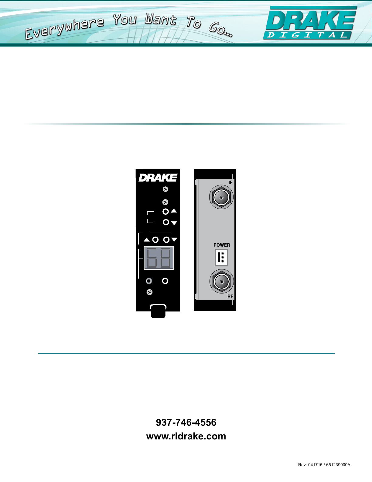
Front and Rear Panel Operation
DUC864A
UP
1
2
3
4
RF LEVEL
UP
CH
+100
DN
DN
ENTER
Specicaons, price, and availability are subject to change without noce or obligaon.
6
7
5
8
FRONT PANEL
1. Up/Down RF Level Buttons: Up & down push button controls for RF level
2. Up/Down Channel Buttons: Up & down push button controls for channel and mode adjustment
3. 2-Digit LED Display: 2 digit LED display for Channel, mode and RF level information
4. +100 Channel LED Indicator: LED illuminates to indicate CATV channels 100 to 135
5. Enter Button: Used to “enter” channel, mode or RF level selection into memory
REAR PANEL
6. IF Input: “F” Connector
7. Power Connector
8. RF Output: “F” Connector
4
937.746.4556 | www.rldrake.com
Page 5

Setting Up the Unit
1. Place the units into the appropriate Drake micro-modular chassis by sliding the unit into the retaining rails.
a. It is recommended to physically place one Down-converter and one up-converter next to one another in the chassis,
if applicable in your installation.
2. Connect the IF source, typically from a DDC864A down-converter to the IF ‘F’ connector of the DUC864A.
3. Connect the RF ‘F’ connector of the DUC864A to the appropriate combining device.
4. Connect to the power supply using one of the power supply cables.
Programming the Unit
The DUC864A unit is intended to accept any digital IF signal and process it to any channel from 54-864 MHz. The unit has
4 valid operating modes, STD CATV, IRC, HRC & Broadcast UHF/VHF. It comes factory set to operate in Standard CATV
Mode. If you wish to change the operating mode skip to the Operating Mode Selection section.
PROGRAMMING A CHANNEL
1. Navigate to the desired channel number by depressing the CH p UP and q DN buttons.
a. Continue past 99 for channels 100-135, the +100 LED will illuminate.
b. Press and hold the CH p UP or q DN arrow button for fast scrolling.
2. Press the ENTER button when you reach the desired channel setting. This will tune the up-converter output to the
corresponding frequency for this entry.
a. The LED display will blink continuously during the channel programming process and will not change the output
channel until the ENTER button is depressed.
b. The unit has a special feature that alerts an operator of an inadvertent or desired change to the unit by flashing LED
readout. The LED will continue to flash for 30 seconds if the ENTER button is not depressed and if no additional
entries are made then the readout will return to the display of the previously programmed channel entry setting.
PROGRAMMING RF LEVEL
Depress the RF Level p UP or q DN buttons to increment or decrement the RF output level to the desired setting.
1.
a. The unit has a specified adjustment range of +35 dBmV to +45 dBmV output. The unit software however, will permit
entries from +33 to +47 dBmV, the out of range entries of 33-34 & 46-47 dBmV are meant for usage to correct any
display error, allowing the unit to be operated in the specified range.
ATTENTION: It is also recommended to set the output level to +45 dBmV for optimum noise performance and externally
attenuate down to a desired level.
2. Press the ENTER button when you reach the desired channel setting. This will tune the up-converter output to the
corresponding frequency for this entry.
a. The LED display readout will also flash continuously during the RF Level programming process. The LED display
will continue to flash for 30 seconds if the ENTER button is not depressed and then will return to the display of the
previously programmed channel entry setting.
937.746.4556 | www.rldrake.com
5
Page 6

Operating Mode Selection
The unit has 4 valid operating modes: STD CATV, IRC, HRC & Broadcast UHF/VHF. The DUC864A unit comes factory set
to operate in the Standard CATV mode.
TO CHANGE THE OPERATING MODE
1. Simultaneously depress the CH p UP or q DN buttons for approximately 5 seconds.
2. The Channel LED display will switch to the operating mode selection.
Use the CH p UP or q DN buttons to select the desired mode:
3.
a. C = STD CATV
b. H = HRC
c. I = IRC
d. U = Broadcast (VHF/UHF)
4. After selecting the desired mode depress the ENTER button to set the mode.
5. The unit will return to the channel display mode.
a.
Programming will reflect the mode chosen – See Appendix for detailed frequency plans.
b. The operating mode will also flash continuously during the mode selection process. The LED display will continue
to flash for 30 seconds if the ENTER button is not depressed and then will return to the display of the previously
programmed channel & mode entry setting.
NOTE: The mode presently in memory will be displayed without flashing during the mode selection process.
TROUBLESHOOTING
A continuously flashing Channel Display indicates an
Error Condition detected by the unit microcontroller.
Sample conditions include:
• Channel Selector Entry does not match the channel
number on which the unit is operating, the display
will flash for 30 seconds and then revert back to the
previous CH entry
• E1 is displayed if the Input VCO is Not Locked
• E2 is displayed if the Output VCO is Not Locked
CORRECT SUGGESTION
The User should perform the following steps to correct an
Error Condition:
1. Check that the Channel Display is set to the desired
channel & reset as appropriate.
2. Check that the unit is set to the appropriate desired
operating mode.
3. Verify the unit output on a spectrum analyzer.
4. Disconnect and reconnect power to the unit.
If an error condition continues to be displayed, unit should
be replaced and serviced.
6
937.746.4556 | www.rldrake.com
Page 7

Appendix A
Appendix B
Output
Center Frequencies
VHF Broadcast Channels
Channel (MHz)
2 57
3 63
4 69
5 79
6 85
7 177
8 183
9 189
10 195
11 201
12 207
13 213
UHF Broadcast Channels
Channel (MHz)
14 473
15 479
16 485
17 491
18 497
19 503
20 509
21 515
22 521
23 527
24 533
25 539
26 545
27 551
28 557
29 563
30 569
31 575
32 581
33 587
34 593
35 599
36 605
37 611
38 617
39 623
40 629
41 635
42 641
43 647
44 653
45 659
46 665
47 671
48 677
49 683
50 689
51 695
52 701
53 707
54 713
55 719
56 725
57 731
58 737
59 743
60 749
61 755
62 761
63 767
64 773
65 779
66 785
67 791
68 797
69 803
Output
Center Frequencies
EIA Standard Incremental Harmonic
Chan. CATV
2 57 57 55.75
3 63 63 61.75
4 69 69 67.75
1 75 73.75
5 79 81 79.75
6 85 87 85.75
95 93 93 91.75
96 99 99 97.75
97 105 105 103.75
98 111 111 109.75
99 117 117 115.75
14 123 123 121.75
15 129 129 127.75
16 135 135 133.75
17 141 141 139.75
18 147 147 145.75
19 153 153 151.75
20 159 159 157.75
21 165 165 163.75
22 171 171 169.75
7 177 177 175.75
8 183 183 181.75
9 189 189 187.75
10 195 195 193.75
11 201 201 199.75
12 207 207 205.75
13 213 213 211.75
23 219 219 217.75
24 225 225 223.75
25 231 231 229.75
26 237 237 235.75
27 243 243 241.75
28 249 249 247.75
29 255 255 253.75
30 261 261 259.75
31 267 267 265.75
32 273 273 271.75
33 279 279 277.75
34 285 285 283.75
35 291 291 289.75
36 297 297 295.75
37 303 303 301.75
38 309 309 307.75
39 315 315 313.75
40 321 321 319.75
41 327 327 325.75
42 333 333 331.75
43 339 339 337.75
44 345 345 343.75
45 351 351 349.75
46 357 357 355.75
47 363 363 361.75
48 369 369 367.75
49 375 375 373.75
50 381 381 379.75
51 387 387 385.75
52 393 393 391.75
53 399 399 397.75
54 405 405 403.75
55 411 411 409.75
56 417 417 415.75
57 423 423 421.75
58 429 429 427.75
59 435 435 433.75
60 441 441 439.75
61 447 447 445.75
62 453 453 451.75
(IRC)
(HRC)
EIA Standard Incremental Harmonic
Chan.
63 459 459 457.75
64 465 465 463.75
65 471 471 469.75
66 477 477 475.75
67 483 483 481.75
68 489 489 487.75
69 495 495 493.75
70 501 501 499.75
71 507 507 505.75
72 513 513 511.75
73 519 519 517.75
74 525 525 523.75
75 531 531 529.75
76 537 537 535.75
77 543 543 541.75
78 549 549 547.75
79 555 555 553.75
80 561 561 559.75
81 567 567 565.75
82 573 573 571.75
83 579 579 577.75
84 585 585 583.75
85 591 591 589.75
86 597 597 595.75
87 603 603 601.75
88 609 609 607.75
89 615 615 613.75
90 621 621 619.75
91 627 627 625.75
92 633 633 631.75
93 639 639 637.75
94 645 645 643.75
100 651 651 649.75
101 657 657 655.75
102 663 663 661.75
103 669 669 667.75
104 675 675 673.75
105 681 681 679.75
106 687 687 685.75
107 693 693 691.75
108 699 699 697.75
109 705 705 703.75
110 711 711 709.75
111 717 717 715.75
112 723 723. 721.75
113 729 729 727.75
114 735 735 733.75
115 741 741 739.75
116 747 747 745.75
117 753 753 751.75
118 759 759 757.75
119 765 765 763.75
120 771 771 769.75
121 777 777 775.75
122 783 783 781.75
123 789 789 787.75
124 795 795 793.75
125 801 801 799.75
126 807 807 805.75
127 813 813 811.75
128 819 819 817.75
129 825 825 823.75
130 831 831 829.75
131 837 837 835.75
132 843 843 841.75
133 849 849 847.75
134 855 855 853.75
135 861 861 859.75
CATV
(IRC) (HRC)
937.746.4556 | www.rldrake.com
7
Page 8

Limited Warranty
THREE YEAR LIMITED WARRANTY
R.L. DRAKE LLC warrants to the original purchaser this product shall be free from defects in material or workmanship for
three (3) years from the date of original purchase.
During the warranty period the R.L. DRAKE LLC or an authorized Drake service facility will provide, free of charge, both
parts and labor necessary to correct defects in material and workmanship. At its option, R.L. DRAKE LLC may replace a
defective unit.
To obtain such a warranty service, the original purchaser must:
(1) Retain invoice or original proof of purchase to establish the start of the warranty period.
(2) Notify the R.L. DRAKE LLC or the nearest authorized service facility, as soon as possible after discovery of a
possible defect, of:
(a) the model and serial number,
(b) the identity of the seller and the approximate date of purchase; and
(c) A detailed description of the problem, including details on the electrical connection to associated
equipment and the list of such equipment.
(3) Deliver the product to the R.L. DRAKE LLC or the nearest authorized service facility, or ship the same in its
original container or equivalent, fully insured and shipping charges prepaid.
Correct maintenance, repair, and use are important to obtain proper performance from this product. Therefore carefully
read the Instruction Manual. This warranty does not apply to any defect that R.L. DRAKE LLC determines is due to:
Allimpliedwarranties,ifany,includingwarrantiesofmerchantabilityandtnessforaparticularpurpose,terminatethree
(3) years from the date of the original purchase.
The foregoing constitutes R.L. DRAKE LLC's entire obligation with respect to this product, and the original purchaser shall
have no other remedy and no claim for incidental or consequential damages, losses or expenses. Some states do not
allow limitations on how long an implied warranty lasts or do not allow the exclusions or limitation of incidental or consequential damages, so the above limitation and exclusion may not apply to you.
Thiswarrantygivesyouspeciclegalrightsandyoumayalsohaveotherrightswhichvaryfromstatetostate.
This warranty shall be construed under the laws of Ohio.
(1) Improper maintenance or repair, including the installation of parts or accessories that do not conform to the
qualityandspecicationsoftheoriginalparts.
(2) Misuse, abuse, neglect or improper installation.
(3) Accidental or intentional damage.
R.L. DRAKE HOLDINGS, LLC
Sales: 937-746-4556 • Support: 937-746-6990 • Fax: 937-806-1510
www.rldrake.com
 Loading...