

DRAKE DUC864 User Manual
1 DUC864 DIGITAL UPCONVERTER
TM
2
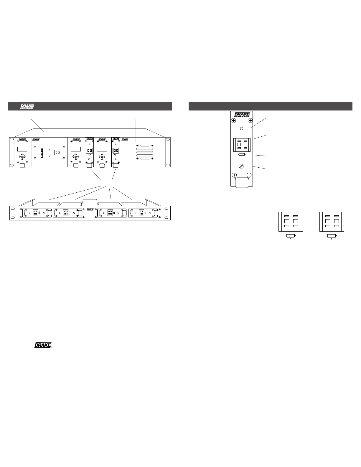
FRONT PANEL CONTROLS and INDICATORS
Figure 1
For example: For example:
Setting for CATV Setting for CATV
channel "125"- channel "25"-
F1
F2
F3
F4
F1 - POWER/ERROR Indicator
Lights when the unit is connected to the
required source of DC power via the rear panel
DC INPUT connector. A flashing condition
indicates an invalid channel setting or other
conditions that would cause the unit to operate
on an invalid channel. The RF output is
switched off for flashing (ERROR) conditions.
F2 - Channel Number Switch
Sets the desired operating channel for standard
CATV or Broadcast channel plans. See also
Item F3 which sets the type of channel (CATV
or Broadcast TV) and sets the leading “1” for
CATV channels 100 through 135.
TM is a trademark of the R.L. Drake Company
is a registered trademark of the R.L. Drake Company
© Copyright 2005 R.L. Drake Company P/N: 3852387A-10-2005 Printed in the U.S.A.
The R.L. Drake DUC864 is a low noise
upconverter used to translate the 44 MHz
digital IF signal from a QAM or VSB modulator,
DDC downconverter, or other similar equipment to the desired CATV or off-air output
channel. A single model covers the entire 54 to
860 MHz output range. The DUC864 features
low phase noise and can be used for QAM
modulation up to 256 QAM. This module can be
rack mounted using the DRMM4 or DRMM12
rack mount. The PS8 power supply module is
required with the DRMM12.
F3 - Channel Mode Switch
Sets the type of channel, CATV or Broadcast.
The CATV +100 mode sets a leading “1” for
CATV channels 100 through 135.
TMQAM
QAM
MODULATOR
BIT RATE
19.327 M
ENTER ENTER
19.327 M
BIT RATE
MODULATOR
QAM
TMQAM
SNR
14 dB
23 dB
TD8VSB
8-VSB DEMODULATOR
25
CHANNEL
LOCK
ERROR
25
DUC864
GAIN
PWR/
ERROR
CATV
+100BCTV
CATV
TMQAM
QAM
MODULATOR
BIT RATE
19.327 M
ENTER
CATV
TVBC+100
CATV
PWR/
GAIN
DUC864
25
PS8
POWER SUPPLY
ERROR
DUC864
25
DUC864
GAIN
PWR/
ERROR
CATV
+100
BC
TV
CATV
CATV
TV
BC
+100
CATV
ERROR
PWR/
GAIN
DUC864
25
CATV
TV
BC
+100
CATV
ERROR
PWR/
GAIN
DUC864
25
CATV
TV
BC
+100
CATV
ERROR
PWR/
GAIN
DUC864
25
CATV
TV
BC
+100
CATV
ERROR
PWR/
GAIN
DUC864
25
DRMM4
F4 - GAIN Control
This control sets the RF output level. The full
clockwise setting is a minimum output of
+45 dBmV.
12 POSITION RACK MOUNT POWER SUPPLY
25 25
CATV
+100
CATV CATV
+100
CATVBC
TV TV
BC
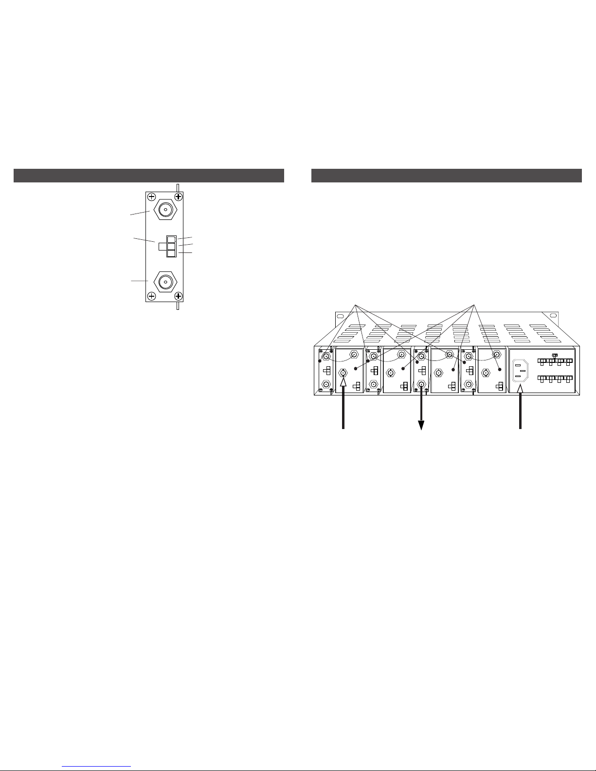
3 REAR P ANEL CONNECTIONS
4
INSTALLATION
R1
R2
R3
R1 - IF INPUT Connector
This is the 44 MHz IF input. The required level
is +30 dBmV (from TMQAM or DDC, etc).
R2 - DC INPUT Connector
This 3-pin connector (Male) accepts the
appropriate mating DC power cable. Observe
proper orientation and wiring.
R3 - RF OUTPUT Connector
This is the upconverter output.
Figure 2
+12 V
GND
+5 V
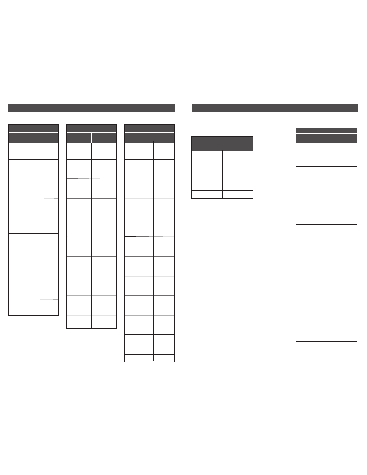
CONNECTIONS AND CONTROLS
All connections to and from each upconverter
are made through the rear panel.
DESCRIPTION
Figure 3 shows a typical installation utilizing 4
DUC864 upconverters used with 4 TMQAM
modulators. A PS8 power supply module is
used to power all units.
Figure 3
QAM MODULATOR
UNITS
AC POWER
CONNECTOR
TO QAM
DISTRIBUTION
FROM SATELLITE
DEMODULATOR OR
OTHER ASI DATA
STREAM
DUC864
UPCONVERTERS
RACK MOUNTING
Adequate ventilation is very important in
multichannel installations. Units should be
spaced apart by at least one panel height
wherever possible, and some air movement is
mandatory in enclosed rack cabinets. Excessive heat will shorten component life and
modulator performance will be degraded
without proper cooling.
IF IN
POWER
+12 V
GND
+5 V
RF OUT
100-240 V ~
50/60 Hz
85 WATTS
12V GND 5V
DC OUTPUTS X 8
DC OUTPUT RATING.
TOTAL OF ALL OUTPUTS: +5V:6A MAX.
+12V:2.5A MAX.
44 MHz
IF OUTPUT
ASI TRANSPORT
STREAM INPUT
POWER
+12 V
+5 V
GND
RF OUT
+5 V
GND
+12 V
POWER
IF IN
RF OUT
+5 V
GND
+12 V
POWER
IF IN
44 MHz
IF OUTPUT
ASI TRANSPORT
STREAM INPUT
POWER
+12 V
+5 V
GND
RF OUT
+5 V
GND
+12 V
POWER
IF IN
44 MHz
IF OUTPUT
ASI TRANSPORT
STREAM INPUT
POWER
+12 V
+5 V
GND
RF OUT
+5 V
GND
+12 V
POWER
IF IN
44 MHz
IF OUTPUT
ASI TRANSPORT
STREAM INPUT
POWER
+12 V
+5 V
GND
6
CHANNEL FREQUENCIES, continued
5 CHANNEL FREQUENCIES
Channel
Number
CABLE TV CHANNELS
Center of
Channel
EIA/NCTA
Numeric
Equivalent
2
3
4
5
6
95
96
97
98
99
14
15
16
17
18
19
20
21
22
7
8
9
10
11
12
13
23
24
25
26
27
28
29
30
31
32
33
34
35
36
Frequency
in MHz
57
63
69
79
85
93
99
105
111
117
123
129
135
141
147
153
159
165
171
177
183
189
195
201
207
213
219
225
231
237
243
249
255
261
267
273
279
285
291
297
Channel
Number
CABLE TV CHANNELS
Center of
Channel
EIA/NCTA
Numeric
Equivalent
79
80
81
82
83
84
85
86
87
88
89
90
91
92
93
94
100
101
102
103
104
105
106
107
108
109
110
111
112
113
114
115
116
117
118
119
120
121
122
123
124
125
126
127
128
129
130
131
132
133
134
135
Frequency
in MHz
555
561
567
573
579
585
591
597
603
609
615
621
627
633
639
645
651
657
663
669
675
681
687
693
699
705
711
717
723
729
735
741
747
753
759
765
771
777
783
789
795
801
807
813
819
825
831
837
843
849
855
861
Channel
Number
CABLE TV CHANNELS
Center of
Channel
EIA/NCTA
Numeric
Equivalent
37
38
39
40
41
42
43
44
45
46
47
48
49
50
51
52
53
54
55
56
57
58
59
60
61
62
63
64
65
66
67
68
69
70
71
72
73
74
75
76
77
78
Frequency
in MHz
303
309
315
321
327
333
339
345
351
357
363
369
375
381
387
393
399
405
411
417
423
429
435
441
447
453
459
465
471
477
483
489
495
501
507
513
519
525
531
537
543
549
Center of Channel
Frequency (MHz)
57
63
69
79
85
177
183
189
195
201
207
213
2
3
4
5
6
7
8
9
10
11
12
13
VHF BROADCAST CHANNELS
Channel
Number
473
479
485
491
497
503
509
515
521
527
533
539
545
551
557
563
569
575
581
587
593
599
605
611
617
623
629
635
641
647
653
659
665
671
677
683
689
695
701
707
713
719
725
731
737
743
749
755
761
767
773
779
785
791
797
803
14
15
16
17
18
19
20
21
22
23
24
25
26
27
28
29
30
31
32
33
34
35
36
37
38
39
40
41
42
43
44
45
46
47
48
49
50
51
52
53
54
55
56
57
58
59
60
61
62
63
64
65
66
67
68
69
Center of Channel
Frequency (MHz)
UHF BROADCAST CHANNELS
Channel
Number
OFF-AIR
Frequencies shown are the center of each 6 MHz wide
channel.
 Loading...