

DRAKE MEQ1000, DTD1000, SDE24, ASII Instruction Manual
MEQ1000 Hybrid QAM Modulator
ENTER
0.000 Mbits/S
QAM OUTPUT
MEQ1000 Multiplexing Edge QAM Modulator
SELECT
DTD1000 Digital Tuner and Demodulator Module
SDE24 Encoder module
ASII ASI Input Module
Instruction Manual
© Copyright 2010 R.L. Drake LLC P/N: 3852511_D-03-2010 Printed in U.S.A.
TM is a trademark of R.L. Drake LLC
is a registered trademark of R.L. Drake LLC
2 Caution Statements
WARNING: TO PREVENT FIRE OR
ELECTRICAL SHOCK DO NOT
EXPOSE TO RAIN OR MOISTURE
CAUTION
RISK OF ELECTRIC SHOCK
DO NOT OPEN
CAUTION: TO REDUCE THE RISK OF ELECTRIC
SHOCK,
DO NOT REMOVE COVER
NO USER-SERVICEABLE PARTS INSIDE
REFER SERVICING TO QUALIFIED PERSONNEL
WARNING:
CAUTION:
TO REDUCE THE RISK OF FIRE OR ELECTRIC SHOCK, DO NOT EXPOSE THIS PRODUCT
TO RAIN OR MOISTURE.
DO NOT OPEN THE CABINET, REFER SERVICING TO QUALIFIED PERSONNEL ONLY.
TO PREVENT ELECTRIC SHOCK, DO NOT USE THIS (POLARIZED) PLUG WITH AN EXTENSION
CORD RECEPTACLE OR OTHER OUTLET UNLESS THE BLADES CAN BE FULLY INSERTED TO
PREVENT BLADE EXPOSURE.
A product and cart combination should be moved
with care. Quick stops, excessive force and uneven
surfaces may cause the product and cart combination to overturn.
The lightning flash with arrow head symbol, within
an equilateral triangle, is intended to alert the user
to the presence of uninsulated "dangerous voltage"
within the product's enclosure that may be of
sufficient magnitude to constitute a risk of electric
shock to persons.
The exclamation point within an equilateral triangle
is intended to alert the user to the presence of
important operating and maintenance (servicing)
instructions in the literature accompanying
the product.
ATTENTION:
POUR PREVENIR LES CHOCS ELECTRIQUES, NE PAS UTILISER CETTE FICHE POLARISEE
AVEC UN PROLONGATEUR, UNE PRISE DE COURANT OU UNE AUTRE SORTIE DE COURANT, SAUF SI LES LAMES PEUVENT ETRE INSEREES A FOND SANS EN LAISSER AUCUNE
PARTIE A DECOUVERT.
The MEQ1000 and its associated input modules have been designed to comply with, and tested to
confirm compliance to, the following satety regulations:
ANSI/UL 60065, 7th Edition, dated 06/30/2004, rev. 11/20/2006.
CAN/CSA - C22.2 No. 60065:03 (2006).

Important Safety Instructions 3
Consignes importantes de sécurité 3
1. Read Instructions—All the safety and operating Instructions should be read
before the product is operated.
1a. Lire les directives -Toutes les directives de sécurité et d’utilisation
devraient être lues avant de mettre l’appareil en opération.
2. Retain Instructions—The safety and operating instructions should be
retained for future reference.
2a. Conserver les directives – Les directives de sécurité et d’utilisation
devraient être conservées pour consultation future.
3. Heed Warnings—All warnings on the product and in the operating
instructions should be adhered to.
3a. Tenir compte des avertissements –Tous les avertissements apparaissant
sur l’appareil et dans les consignes d'utilisation devraient être respectés.
4. Follow instructions - All operating and use instructions should be followed.
4a. Suivre les directives - Toutes les directives d’opération et d'utilisation
devraient être suivies.
5. Cleaning—Unplug this product from the wall outlet before cleaning. Do not
use liquid cleaners or aerosol cleansers. Use a damp cloth for cleaning.
5a. Nettoyage – Débrancher l’appareil de la prise électrique murale avant le
nettoyage. Ne pas utiliser de nettoyants liquides ou aérosols. Employer un linge
humide pour le nettoyage.
6. Attachments—Do not use attachments that are not recommended by the
product manufacturer as they may cause hazards.
6a. Fixation – Ne pas utiliser d’autres fixations que celles recommandées par le
manufacturier; elles pourraient être source de dangers.
7. Water and Moisture—Do not use this product near water—for example,
near a bathtub, wash bowl, kitchen sink or laundry tub; in a wet basement; or
near a swimming pool; and the like.
7a. Eau et humidité – Ne pas utiliser cet appareil près de l’eau. Par exemple,
près d'une baignoire, d’un bac de lavage, d'un évier de cuisine ou d'une cuvette
de lessivage; dans un sous-sol humide; ou à proximité d'une piscine; et autres
environnements similaires.
8. Accessories—Do not place this product on an unstable cart, stand, tripod,
bracket, or table. The product may fall, causing serious injury to a child or adult
and serious damage to the product. Use only with a cart, stand, tripod, bracket,
or table recommended by the manufacturer, or sold with the product. Any
mounting of the product should follow the manufacturer's instructions, and
should use a mounting accessory recommended by the manufacturer.
8a. Accessoires – Ne pas installer cet appareil sur un chariot, un socle, un
trépied, un support ou une table instables. L’appareil pourrait tomber, entraînant
des blessures graves à un enfant ou à un adulte, et des dommages importants à
l’appareil. Employer seulement avec un chariot, un socle, un trépied, un support,
ou une table recommandés par le fabricant ou vendu avec l’appareil. Toute
installation de l’appareil devrait être conforme aux directives du manufacturier et
devrait utiliser des accessoires d’installation recommandés par celui-ci.
9. A product and cart combination should be moved with care. Quick stops,
excessive force, and uneven surfaces may cause the product and cart
combination to overturn.
9a. Un chariot supportant l’appareil devrait être déplacé avec précaution. Les
arrêts brusques, la force excessive et les surfaces inégales peuvent renverser le
chariot.
10. Ventilation—Slots and openings in the cabinet are provided for ventilation
and to ensure reliable operation of the product and to protect it from
overheating, and these openings must not be blocked or covered. The
openings should never be blocked by placing the product on a bed, sofa, rug,
or similar surface. This product should not be placed in a built-in installation
such as bookcase or rack unless proper ventilation is provided or the
manufacturer's instructions have been adhered to.
10a. Ventilation – Des fentes et ouvertures dans le châssis sont prévues pour
la ventilation de l’appareil, pour en assurer la fiabilité d’opération et le protéger
contre la surchauffe. Ces ouvertures ne doivent pas être bloquées ou
recouvertes. Ces ouvertures ne devraient jamais être bloquées en plaçant
l’appareil sur un lit, un sofa, une couverture, ou une surface semblable. Cet
appareil ne devrait pas être installé dans un meuble encastré comme une
bibliothèque ou une étagère à moins de lui fournir une ventilation adéquate ou
que l’installation soit conforme aux directives du manufacturier.
11. Power Sources—This product should be operated only from the type of
power source indicated on the marking label. If you are not sure of the type of
power supplied to your home, consult your product dealer or local power
company. For products intended to operate from battery power, or other
sources, refer to the operating instructions.
11a. Sources d’alimentation électrique - Cet appareil devrait être utilisé
seulement avec le type d’alimentation électrique inscrite sur l’étiquette. Si vous
n'êtes pas certain du type d’alimentation électrique fourni à votre maison,
consultez le vendeur de l’appareil ou l’entreprises d'énergie locale. Pour des
appareils alimentés par une batterie ou d'autres sources, se référer aux
consignes d'utilisation.
12. Grounding or Polarization—This product may be equipped with a
polarized alternating-current line plug (a plug having one blade wider than the
other) This plug will fit into the power outlet only one way. This is a safety
feature. If you are unable to insert the plug fully into the outlet, try reversing the
plug. If the plug should still fail to fit, contact your electrician to replace your
obsolete outlet. Do not defeat the safety purpose of the polarized plug.
Alternate Warnings—If this product is equipped with a three-wire grounding-type
plug, a plug having a third (grounding) pin, the plug will only fit into a groundingtype power outlet. This is a safety feature. If you are unable to insert the plug into
the outlet, contact your electrician to replace your obsolete outlet. Do not defeat
the safety purpose of the grounding-type plug.
12a. Mise à la terre ou polarisation - Cet appareil peut être équipé d'une fiche
électrique de courant alternatif polarisée (une fiche ayant une lame plus large
que l'autre). Cette fiche ne s’insérera correctement dans la prise de courant que
d’une seule façon; c'est un dispositif de sécurité. S’il est impossible d’insérer la
fiche entièrement dans la prise de courant, essayer de renverser la fiche. Si la
fiche ne s’insère toujours pas, contacter un électricien pour remplacer la prise
de courant désuète. Ne pas altérer le dispositif de sécurité de la fiche polarisée.
Mise en garde supplémentaire - Si cet appareil est équipé d'une fiche électrique
à trois broches (une fiche ayant une broche de mise à la terre), la fiche
s'insérera seulement dans une prise de courant équipée d’une mise à la terre;
c'est un dispositif de sécurité. S’il est impossible d’insérer la fiche dans la prise
de courant, contacter un électricien pour remplacer la prise de courant désuète.
Ne pas altérer le dispositif de sécurité de la fiche avec mise à la terre.
13. Power-Cord Protection—Power-supply cords should be routed so that they
are not likely to be walked on or pinched by items placed upon or against them,
paying particular attention to cords at plugs, convenience receptacles, and the
point where they exit from the product.
13a. Protection du cordon d’alimentation - Les cordons d’alimentation
devraient être disposés de façon à ce qu’on ne puisse marcher dessus ou qu’ils
soient susceptibles d’être coincés par des articles placés sur ou contre eux. Une
attention particulière doit être portée aux fiches, prises de courant, et aux points
où ils sortent de l’appareil.
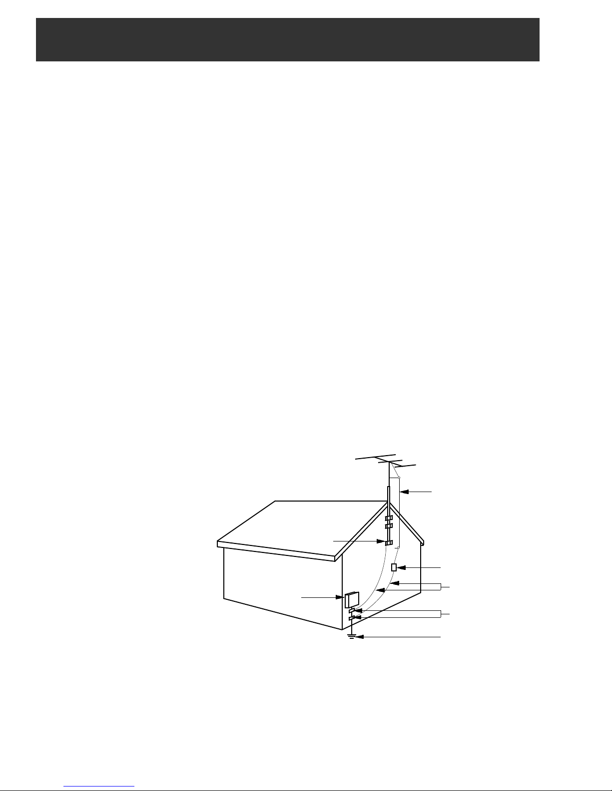
14. Outdoor Antenna Grounding—If an outside antenna or cable system Is
connected to the product, be sure the antenna or cable system is grounded so
as to provide some protection against voltage surges and built-up static
charges. Article 810 of the National Electrical Code, ANSI/NFPA 70, provides
information with regard to proper grounding of the mast and supporting
structure, grounding of the lead-in wire to an antenna discharge unit, size of
grounding conductors, location of antenna-discharge unit, connection to
grounding electrodes, and requirements for the grounding electrode.
See Figure A.
14a. Mise à la terre de l’antenne extérieure - Si un système extérieur
d'antenne ou de câble est relié à l’appareil, s’assurer que le système d'antenne
ou de câble est muni d’une mise à la terre afin de fournir une certaine protection
contre les surtensions et les charges d’électricité statique. L'article 810 du code
électrique national, ANSI/NFPA 70, fournit l'information nécessaire en ce qui
concerne la mise à la terre appropriée du mât et de la structure porteuse, la
mise à la terre du câble de connexion à une unité de décharge d’antenne, le
calibre des conducteurs de mise à la terre, la location de l’unité de décharge
d’antenne, le raccordement aux électrodes de mise à la terre et les
spécifications pour les électrodes de mise à la terre.
Voir la figure A.
15. Lightning—For added protection for this product during a lightning storm,
or when it is left unattended and unused for long periods of time, unplug It from
the wall outlet and disconnect the antenna or cable system. This will prevent
damage to the product due to lightning and power-line surges.
15a. Foudre - Pour une protection supplémentaire de cet appareil pendant un
orage électrique, ou quand il est laissé sans surveillance et inutilisé pendant de
longues périodes, le débrancher de la prise électrique murale et déconnecter le
système d'antenne ou de câble. Ceci préviendra les dommages à l’appareil dus
à la foudre et aux surtensions.
16. Power Lines—An outside antenna system should not be located in the
vicinity of overhead power lines, other electric light or power circuits, where it
can fall into such power lines or circuits. When installing an outside antenna
system, extreme care should be taken to keep from touching such power lines
or circuits as contact with them may be fatal.
16a. Lignes électriques - Un système d'antenne extérieur ne devrait pas être
situé à proximité de lignes électriques aériennes ou de tout autre circuit
électrique, où il pourrait tomber sur de tels circuits ou lignes électriques. Lors de
l’installation d’un système d’antenne extérieur, d’extrêmes précautions devraient
être prises afin de prévenir tout contact avec des lignes ou circuits électriques.
Entrer en contact avec de tels circuits ou lignes électriques pourrait être fatal.
17. Overloading—Do not overload wall outlets, extension cords, or integral
convenience receptacles as this can result in a risk of fire or electric shock.
17a. Surcharge – Ne pas surcharger les prises de courant murales, les
rallonges électriques ou les prises de courant intégrées. Un risque d’incendie ou
de choc électrique pourrait résulter d’une telle surcharge.
4 Important Safety Instructions (cont.)
4 Consignes importantes de sécurité
18. Object and Liquid Entry—Never push objects of any kind into this product
through openings as they may touch dangerous voltage points or short-out parts
that could result in a fire or electric shock. Never spill liquid of any kind on the
product.
18a. Insertion d’objet ou de liquide – Ne jamais insérer d’objet par les
ouvertures de cet appareil. Il pourrait toucher des points de voltage dangereux
ou court-circuiter des pièces, ce qui pourrait résulter en incendie ou en choc
électrique. Ne jamais verser de liquide sur l’appareil.
19. Servicing—Do not attempt to service this product yourself as opening or
removing covers may expose you to dangerous voltage or other hazards. Refer
all servicing to qualified service personnel.
19a. Entretien –Ne pas essayer de faire soi-même l’entretien de cet appareil.
En ouvrir ou en retirer les couvercles pourrait vous exposer à des voltages
dangereux ou à d’autres dangers. Confier tout entretien à un personnel de
service qualifié.
20. Damage Requiring Service—Unplug this product from the wall outlet and
refer servicing to qualified service personnel under the following conditions:
a. When the power-supply cord or plug is damaged,
b. If liquid has been spilled, or objects have fallen into the product,
c. If the product has been exposed to rain or water,
d. If the product does not operate normally by following the operating instruc-
tions. Adjust only those controls that are covered by the operating
instructions as an improper adjustment of other controls may result in damage
and will often require extensive work by a qualified technician to restore the
product to its normal operation,
e. If the product has been dropped or damaged in anyway, and
f. When the product exhibits a distinct change in performance—this indicates a
need for service.
20a. Dommage exigeant un entretien - Débrancher cet appareil de la prise de
courant électrique et confier l'entretien au personnel de service qualifié dans les
éventualités suivantes:
a. Quand le cordon d’alimentation ou sa fiche sont endommagés,
b. Si des objets sont tombés dans l’appareil, ou si du liquide y a été renversé,
c. Si l’appareil a été exposé à la pluie ou à l'eau,
d. Si l’appareil ne fonctionne pas normalement en suivant les consignes
d'utilisation.
Ajuster seulement les commandes qui sont mentionnées dans le guide
d'opération. Un mauvais ajustement des autres commandes pourrait causer des
dommages à l’appareil et souvent exiger un travail supplémentaire de la part
d’un technicien qualifié pour remettre l’appareil en état normal d’opération.
e. Si l’appareil a été échappé ou endommagé de n’importe quelle façon, et
f. Quand l’appareil montre un changement notable de performance – ceci
indique qu’un entretien est nécessaire.
21. Replacement Parts—When replacement parts are required, be sure the
service technician has used replacement parts specified by the manufacturer
or have the same characteristics as the original part. Unauthorized substitutes
may result in fire, electric shock or other hazards.
21a. Pièces de rechange - Si des pièces de rechange sont nécessaires,
s’assurer que le technicien de service a employé des pièces de rechange
spécifiques du manufacturier ou ayant les mêmes caractéristiques que les
pièces originales. L’utilisation de pièces de rechange non autorisées pourrait
résulter en incendie, choc électrique ou autres dangers.
22. Safety Check—Upon completion of any service or repairs to this product,
ask the service technician to perform safety checks to determine that the
product is in proper operating condition.
22a. Vérification de sécurité – À la suite de toute réparation ou entretien de
cet appareil, demander au technicien de service d'exécuter des vérifications de
sécurité afin de s’assurer que l’appareil est en condition normale de
fonctionnement.
23. Wall or Ceiling Mounting—The product should be mounted to a wall or
ceiling only as recommended by the manufacturer.
23a. Montage au mur ou au plafond - L’appareil ne devrait être monté au mur
ou au plafond qu’uniquement de la façon recommandée par le manufacturier.
24. Heat—The product should be situated away from heat sources such as
radiators, heat registers, stoves, or other products (including amplifiers) that
produce heat.
24a. Chaleur – L’appareil devrait être situé loin de sources de chaleur telles que
des radiateurs, des registres de chaleur, des fourneaux, ou d'autres appareils (y
compris amplificateurs) produisant de la chaleur.
NOTE TO CATV SYSTEM INSTALLERS:
THIS REMINDER IS PROVIDEO TO CALL THE
CATV SYSTEM INSTALLER'S ATTENTION TO
ARTICLE 820 - 40 OF THE NEC THAT PROVIDES
GUIDELINES FOR PROPER GROUNDING AND,
IN PARTICULAR, SPECIFIES THAT THE CABLE
GROUND SHALL BE C0NNECTED TO THE
GROUNDING SYSTEM OF THE BUILDING, AS
CLOSE TO THE POINT OF CABLE ENTRY AS
PRACTICAL.
NOTE AUX INSTALLATEURS DE SYSTÈME DE
CATV :
CE RAPPEL EST FOURNI POUR PORTER À
L’ATTENTION DES INSTALLATEURS DE
SYSTÈME DE CATV, L'ARTICLE 820 - 40 DU NEC
QUI DONNE DES DIRECTIVES POUR UNE MISE
À LA TERRE APPROPRIÉE ET, EN
PARTICULIER, SPÉCIFIE QUE LE CÂBLE DE
MISE À LA TERRE DEVRAIT ÊTRE RACCORDÉ
AU SYSTÈME DE MISE À LA TERRE DU
BÂTIMENT LE PLUS PRÈS POSSIBLE DE
L’ENTRÉE DU CÂBLE.
Example of antenna grounding as per National Electrical Code, ANSI/NFPA 70
Exemple de mise à la terre d’antenne selon le code électrique national, ANSI/NFPA 70
GROUND CLAMP
ELECTRIC
SERVICE
EQUIPMENT
NEC - NATIONAL ELECTRIC CODE
NEC – CODE ÉLECTRIQUE NATIONAL
Figure A
ANTENNA LEAD IN WIRE
CÂBLE DE CONNEXION DE
L’ANTENNE
ANTENNA DISCHARGE UNIT
(NEC SECTION 810-20)
UNITÉ DE DÉCHARCHE
D’ANTENNE
GROUNDING CONDUCTORS
(NEC SECTION 810-21)
CONDUCTEURS DE MISE À LA
TERRE
GROUND CLAMPS
ATTACHES DE MISE À LA
TERRE
POWER SERVICE GROUNDING
ELECTRODE SYSTEM (NEC
ART 250. PART H)
SYSTÈME DE MISE À LA TERRE
DU BÂTIMENT

Table of Contents / Specifications 5
TABLE OF CONTENTS
2 Caution Statements
3 Important Safety Instructions
5 Table of Contents / Specifications
6 General Description
7 Installation and Mounting / Front Panel Controls
8 Rear Panel Controls and Connections
9 Setup and Programming / Software Flow Chart
SPECIFICATIONS
SDE24 DUAL PROGRAM ENCODER MODULE
Analog Interface
Composite video Inputs
Composite Video Input Level
S Video Inputs
Composite or S Video select
Audio Inputs, for 2 programs
Audio Input Level
MPEG Encoder
Encode Format - #1 input
Encode Format - #2 input
Encoding Bitrate
Video Adjustments
Audio Encoder
Selectable types
AC3 Encoder
Output bitrate
Output
DTD1000 DEMODULATOR (S)
Input Frequency Range:
Channel Plans (Menu selectable)
Input Channel Bandwidth:
Input RF Level Range:
Input Impedance:
Input Return Loss:
Image rejection:
Adjacent Channel Rejection:
Noise Figure:
Demodulation Modes:
Symbol Rates:
2 composite inputs, one for
each program
1 Volt p-p ± 3 dB
2 S Video connectors, one
for each program
User selectable for each
program input
RCA type for L and R audio
channels, 2 sets
1 Vrms or 2 Vrms user
selectable and user
adjustable audio gain ± 15dB
MPEG2 or MPEG4 H.264,
selectable
MPEG2 only
Constant Bitrate: 1 Mbps to
8 Mbps
Brightness, Contrast,
Saturation, Hue
AC3 - Dolby digital Stereo
MP2 - MPEG1, Layer 2
Manufactured under license
from Dolby Laboratories.
320 kbps
The output of each SDE24
module is connected
internally to the multiplexers
that are included in the
MEQ1000 chassis.
Input Module
54 to 1000 MHz.
Std. CATV, HRC, IRC, or
Broadcast
:
6 MHz.
-33 dBmV to +35 dBmV,
8VSB
-22 dBmV to +35 dBmV, 64
QAM
-17 dBmV to +35 dBmV, 256
QAM
75 Ohms
> 6 dB, Broadcast mode; >
12 dB, CATV mode.
80 dB.
40 dB
< 9 dB, Broadcast mode; <
12 dB, CATV mode.
8VSB - ATSC
64QAM, 256QAM, - ITUB,
CATV mode.
10.76 MS/s, 8VSB; 5.057
MS/s, 64QAM; 5.3606MS/s,
256 QAM
OR
12 Setup and Programing (Continued) / Operation
13 Operating Instructions for Drake Digital Headend Program
14 Additional Information
15 CATV Channel Frequencies
16 Broadcast TV Channel Frequencies
17 Service / If You Need To Call For Help
18 Warranty
SPECIFICATIONS (Continued)
ASII ASI INPUT
ASI Input Clock:
ASI Input Data Rate:
MEQ1000
Modulation Modes:
Symbol Rate:
I/Q Phase Error:
Carrier Suppression:
Channel Amplitude Error:
MER:
MEQ1000
Output Frequency Range:
Channel Plan:
Frequency Stability:
Maximum Output Level:
Minimum Output Level:
Output Level Accuracy:
Output Impedance:
Spurious Outputs:
Broadband Noise:
Phase Noise:
MEQ1000
Data Link:
RS232 Input:
RS232 Output:
MEQ1000
GENERAL
Power:
Weight:
Operating Temperature:
Input Module
270 MHz
Maximum of 80 Mbps per ASII module.
QAM Modulator
16QAM, 32QAM, 64QAM, 128QAM,
256QAM, 512QAM or 1024QAM.
1 Ms/s to 7 Ms/s.
FEC:
ITUA (DVB) or ITUB (DigiCipher).
Less than 1 degree.
45 dB.
Less than 1 dB.
Greater than 38 dB with blind equalizer.
Upconverter RF Output
54 MHz to 1002 MHz.
Std. CATV, HRC, IRC, or Broadcast
± 5 ppm.
+ 61 dBmV minimum, adjustable
downward.
+ 45 dBmV.
± 1 dB.
75 Ohms with return loss better than 14
dB (within output filter passband).
-60 dBc from 40 MHz to 1000 MHz.
Less than -12 dBmV (6 MHz BW @ ±12
MHz).
-101 dBc @ 10 kHz offset
RS232 Control
2400, 4800, 9600, or 19,200 baud
interface via serial cable.
DB-9 connector for connection to
modem or PC.
DB-9 connector for connection to
addtional transcoders.
ASI OUTPUT
The ASI output provides a copy of the
transport stream that is input to the QAM
modulator.
90 - 132 VAC/ 60 Hz, 35 W maximum.
9.5 pounds
Size:
19” W x 1.75” H x 14.5” D.
0 degrees C to + 50 degrees C
Specifications subject to change without notice or obligation.

6 General Description
ENTER
0.000 Mbits/S
QAM OUTPUT
MEQ1000 Multiplexing Edge QAM Modulator
SELECT
GENERAL DESCRIPTION
The R.L. Drake model MEQ1000 is a commercial grade hybrid
QAM modulator. The MEQ1000 features plug in input modules
that include an ATSC/QAM tuner, an ASI input, an IP input, and
analog NTSC inputs; thus the description 'hybrid' is used to
describe it. A multiplexer is built in to combine the transport
streams and input the filtered and groomed transport stream to
the QAM modulator. This manual includes the SDE24 Dual
Program Encoder Module, the DTD1000 input module and ASII.
Other input modules will have instructions provided with them.
Each commercial quality SDE24 module contains two encoders
and if MPEG2 encoding is desired for two programs, two MPEG2
transport streams can be generated. If MPEG4, H.264 encoding
is desired, each SDE24 module can encode one program to an
H.264 output stream. Another option is to encode one program in
MPEG2 and another program in H.264
Each SDE24 module provides two sets of input connectors for
NTSC composite or S-video with stereo audio. Audio is encoded
using Dolby AC-3 encoding.The SDE24 encoder modules provide
standard definition encoding. The SDE24 encoders accept
analog NTSC video input from either composite or S video
sources and provide commercial quality MPEG2 or H.264, 480i
video outputs in both DVB-ASI and RF QAM.
The MEQ1000 has two input module slots and the outputs
interface to the MEQ1000 multiplexer, internally, where they are
MPEG program filtered, multiplexed, and groomed. Programs,
among the total group from input module A and input module B,
may be selected or not selected by the operator to be sent to the
QAM modulator. Each input must contain no more than 20
programs and a maximum of 20 programs per input may be
selected. Also, the total bitrate of the selected programs must not
exceed that of the output QAM channel capacity.
Some common applications include: drop/add, cherry picking
programs from ASI or IP MPTS inputs, digital channel processing,
or local origination additions.
The MEQ1000 contains a high performance QAM modulator that
can operate in most ITU-A or ITU-B modes up through 1024
QAM. The very low noise, high output, upconverter provides
coverage from 54 MHz to 1002 MHz while maintaining exceptionally low phase noise and broadband noise. Output level can be
selected at a value between + 45 and + 61 dBmV.
The MEQ1000 operates in a fixed output clock mode and
processes null packets when required to maintain the set fixed
clock rate. PCR correction is included.
DIGITAL CHANNEL PROCESSING (One input module)
The DTD1000 input module tunes any 8VSB or QAM channel
between 54 and 1002 MHz. It is ideal for digital 'channel processing' applications where a single digital video signal is received,
error corrected, clocked at a user determined fixed rate and
remodulated on the same or another RF channel. Applications
include cleaning up a low MER QAM signal received from a
CATV source or fiber link receiver, or shifting the RF frequency of
a QAM modulated signal. It may be used to convert one off-air
ATSC 8VSB signal to a QAM output with rate adjustment. Used in
the processor mode with only one input, the DQT1000 can
process ATSC or CATV QAM inputs. No multiplexing or altering
of any MPEG tables is performed in this mode.
Used in the non multiplexing mode, the data rate of the incoming
signal can be any rate that falls within the specification range.
The output rate can be set to any fixed output rate (equal to or
faster than the input rate).
MULTIPLEXING TWO ATSC TRANSPORT STREAMS
Utilizing two DTD1000 input modules, two off-air 19.4 Mbps ATSC
signals (QAM modulated CATV delivered signals could also be
used) can be received and multiplexed to obtain a 38.8 Mbps
256QAM output. Thus two ATSC inputs can be output on a single
6 MHz bandwidth 256 QAM channel.
Another way of combining two ATSC 19.4 Mbps streams is to
receive the first stream using the 8VSB input (DTD1000) and
input the second stream, if available in ASI format, through the
ASII module in the second input slot. Again the two combined
ATSC signals will be modulated at 256QAM in a 6 MHz wide
channel.
If it is desired to provide both ATSC signals from two ASI sources,
two ASII modules can be used.
When the MEQ1000 is used as described above, no loss of
picture or sound packets occurs. There is no added compression
of the video or audio streams. Only the necessary control
packets are rewritten to prevent duplication of MPEG2 program
numbers and major and minor channel number assignments in
the tables.
Using a PC interface, the operator can select the major and minor
program numbers that he desires for each program in the output
multiplex.
PROGRAM FILTERING
A 'Select Program' function is provided to allow the operator to
select which of the MPEG programs present on the A and B input
streams are to be included in the output multiplex.
PSIP OPTIONS
When operating in the multiplex mode, the MEQ1000 can be set
to process PSIP information from both sources and rewrite tables
containing combined PSIP information, or in cases where the offair broadcast channels may not be transmitting some or all of the
tables, it can be set to ignore and discard the PSIP tables
completely, or it can be set to generate MGT and VCT tables
without EIT tables. Null packet processing is applied as necessary to keep the output data rate at the desired setting. PCR
correction is provided. The operator can program desired major
and minor channel numbers for each program in the output
stream.
OUTPUTS - RF and ASI
The 54 to 1000 MHz RF output is always QAM regardless of
whether the input is VSB or QAM. This same filtered stream is
also output via the rear panel ASI output jack.
 Loading...