

DRAKE DSE24A Instruction Manual
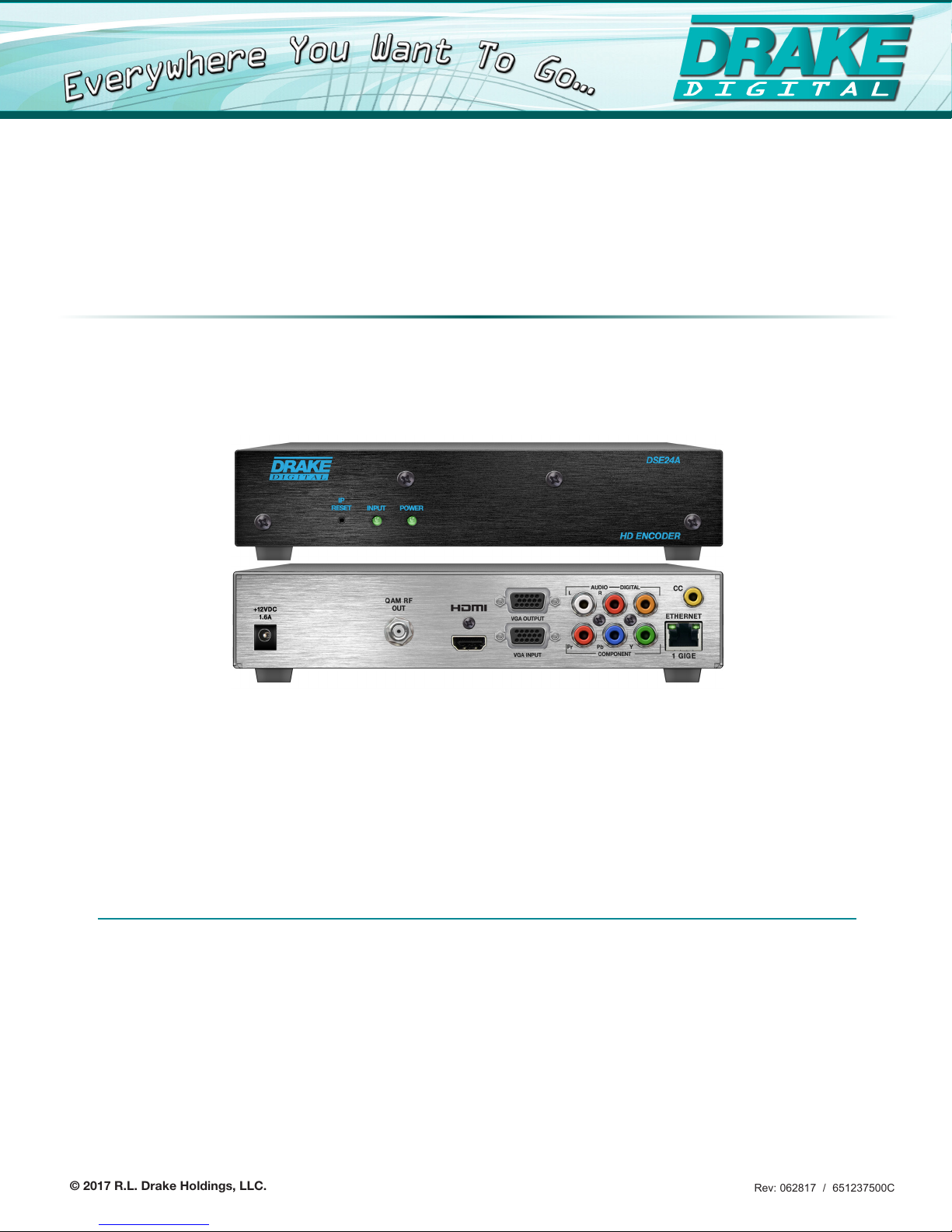
DSE24A
Digital Signage MPEG-2 Encoder with QAM Output
INSTRUCTION MANUAL
Model Item # Description
DSE24A 1002571A Digital Signage MPEG-2 Encoder with QAM Output
DSE24A Rack Panel 1002565A Rack Mount Panel for (2) DSE24A Encoders
© 2017 R.L. Drake Holdings, LLC.
Rev: 062817 / 651237500C

We recommend that you write the following information in the spaces provided below.
Purchase Location Name:
Purchase Location Telephone Number:
DSE24A Serial Number:
This product incorporates copyright protection technology that is protected by U.S. patents and other
intellectual property rights. Reverse engineering or disassembly is prohibited.
Manual Revision
Rev. C: Manual adds support for custom video and transport stream bit rate settings. (firmware v1.0.1)
Rev B: Manual adds cross link cable to Installation & Setup – Unpacking on page 10.
Rev A: First User Manual for DSE24A Encoder. (firmware v0.9.0.0)
2

Table of Contents
GENERAL & SAFETY INFORMATION
SAFETY INSTRUCTIONS & CAUTION STATEMENTS ......................................................................................................... 4
GENERAL DESCRIPTION & FEATURES ............................................................................................................................... 6
SPECIFICATIONS .................................................................................................................................................................... 7
FRONT AND REAR PANEL OPERATION .............................................................................................................................. 8
INSTALLATION & SETUP
INSTALLATION & POWER-UP ............................................................................................................................................... 10
COMMUNICATING WITH THE UNIT ..................................................................................................................................... 11
UNIT CONFIGURATION
ACCESSING THE UNIT VIA WEB BROWSER .................................................................................................................... 12
MAIN TAB ............................................................................................................................................................................... 13
STATUS SCREEN .................................................................................................................................................................................. 13
VIDEO SCREEN .................................................................................................................................................................................... 14
AUDIO SCREEN ....................................................................................................................................................................................15
TS CONFIG SCREEN ............................................................................................................................................................................ 16
IP SCREEN ............................................................................................................................................................................................ 18
QAM SCREEN ....................................................................................................................................................................................... 19
OUTPUT SCREEN ................................................................................................................................................................................. 20
REFRESH TAB ...................................................................................................................................................................................... 21
NETWORK TAB ..................................................................................................................................................................... 21
ADMIN TAB ............................................................................................................................................................................ 22
TIME TAB ............................................................................................................................................................................... 25
EVENT LOG TAB ................................................................................................................................................................... 26
APPENDIX
A. VIEWING IP OUTPUT ON VLC MEDIA PLAYER ............................................................................................................ 27
SERVICE & WARRANTY
SERVICE .................................................................................................................................................................................. 30
WARRANTY ............................................................................................................................................................................. 31
3
Important Safety Instructions
1. Read Instrucons—All the safety and operang instrucons should be read before the
product is operated.
2. Retain Instrucons—The safety and operang instrucons should be retained for future
reference.
3. Heed Warnings—All warnings on the product and in the operang instrucons should be
adhered to.
4. Follow Instrucons—All operang and use instrucons should be followed.
5. Cleaning—Unplug this product from the wall outlet before cleaning. Do not use liquid
cleaners or aerosol cleansers. Use a damp cloth for cleaning.
6. Aachments—Do not use aachments that are not recommended by the product manufacturer as they may cause hazards.
7. Water and Moisture—Do not use this product near water—for example, near a bathtub,
wash bowl, kitchen sink or laundry tub; in a wet basement; or near a swimming pool; and
the like.
8. Accessories—Do not place this product on an unstable cart, stand, tripod, bracket, or
table. The product may fall, causing serious injury to a child or adult, and serious damage
to the product. Use only with a cart, stand, tripod, bracket, or table recommended by the
manufacturer, or sold with the product. Any mounng of the product should follow the
manufacturer’s instrucons, and should use a mounng accessory recommended by the
manufacturer.
9. A product and cart combinaon should be moved with care. Quick stops, excessive force,
and uneven surfaces may cause the product and cart combinaon to overturn.
10. Venlaon—Slots and openings in the cabinet are provided for venlaon and to ensure
reliable operaon of the product and to protect it from overheang, and these openings
must not be blocked or covered. The openings should never be blocked by placing the
product on a bed, sofa, rug, or similar surface. This product should not be placed in a built-in
installaon such as bookcase or rack unless proper venlaon is provided or the manufacturer’s instrucons have been adhered to.
11. Power Sources—This product should be operated only from the type of power source
indicated on the marking label. If you are not sure of the type of power supplied to your
home, consult your product dealer or local power company. For products intended to operate from baery power, or other sources, refer to the operang instrucons.
12. Grounding or Polarizaon—This product may be equipped with a polarized alternatingcurrent line plug (a plug having one blade wider than the other). This plug will t into
the power outlet only one way. This is a safety feature. If you are unable to insert the plug
fully into the outlet, try reversing the plug. If the plug should sll fail to t, contact your
electrician to replace your obsolete outlet. Do not defeat the safety purpose of the polarized
plug. Alternate Warnings—If this product is equipped with a three-wire grounding-type
plug, a plug having a third (grounding) pin, the plug will only t into a grounding-type power
outlet. This is a safety feature. If you are unable to insert the plug into the outlet, contact
your electrician to replace your obsolete outlet. Do not defeat the safety purpose of the
grounding-type plug.
13. Power-Cord Protecon—Power-supply cords should be routed so that they are not
likely to be walked on or pinched by items placed upon or against them, paying parcular
aenon to cords at plugs, convenience receptacles, and the point where they exit from the
product.
14. Outdoor Antenna Grounding—If an outside antenna or cable system is connected to the
product, be sure the antenna or cable system is grounded so as to provide some protecon
against voltage surges and built-up stac charges. Arcle 810 of the Naonal Electrical Code,
ANSI/NFPA 70, provides informaon with regard to proper grounding of the mast and supporng structure, grounding of the lead-in wire to an antenna discharge unit, size of grounding conductors, locaon of antenna-discharge unit, connecon to grounding electrodes, and
requirements for the grounding electrode. See Figure A.
15. Lightning—For added protecon for this product during a lightning storm, or when it
is le unaended and unused for long periods of me, unplug it from the wall outlet and
disconnect the antenna or cable system. This will prevent damage to the product due to
lightning and power-line surges.
16. Power Lines—An outside antenna system should not be located in the vicinity of overhead power lines, other electric light or power circuits, where it can fall into such power lines
or circuits.
17. Overloading—Do not overload wall outlets, extension cords, or integral convenience
receptacles as this can result in a risk of re or electric shock.
18. Object and Liquid Entry—Never push objects of any kind into this product through openings as they may touch dangerous voltage points or short-out parts that could result in a re
or electric shock. Never spill liquid of any kind on the product.
19. Servicing—Do not aempt to service this product yourself as opening or removing covers may expose you to dangerous voltage or other hazards. Refer all servicing to qualied
service personnel.
20. Damage Requiring Service—Unplug this product from the wall outlet and refer servicing
to qualied service personnel under the following condions:
a. When the power-supply cord or plug is damaged,
b. If liquid has been spilled, or objects have fallen into the product,
c. If the product has been exposed to rain or water,
d. If the product does not operate normally by following the operang instrucons. Adjust
only those controls that are covered by the operang instrucons as an improper adjustment of other controls may result in damage and will oen require extensive work by a
qualied technician to restore the product to its normal operaon,
e. If the product has been dropped or damaged in any way, and
f. When the product exhibits a disnct change in performance—this indicates a need for
service.
21. Replacement Parts—When replacement parts are required, be sure the service technician has used replacement parts specied by the manufacturer or have the same characteriscs as the original part. Unauthorized substutes may result in re, electric shock or other
hazards.
22. Safety Check—Upon compleon of any service or repairs to this product, ask the service
technician to perform safety checks to determine that the product is in proper operang
condion.
23. Wall or Ceiling Mounng—The product should be mounted to a wall or ceiling only as
recommended by the manufacturer.
24. Heat—The product should be situated away from heat sources such as radiators, heat
registers, stoves, or other products (including ampliers) that produce heat.
CAUTION STATEMENT
WARNING: TO PREVENT FIRE OR
ELECTRICAL SHOCK DO NOT
EXPOSE TO RAIN OR MOISTURE
! CAUTION !
RISK OF ELECTRIC SHOCK
DO NOT OPEN
WARNING: TO REDUCE THE RISK OF ELECTRIC SHOCK, DO NOT
An appliance and cart combinaon should be moved with care. Quick stops, excessive
force and uneven surfaces may cause the appliance and cart combinaon to overturn.
The lightning ash with arrow head symbol, within an equilateral triangle, is intended to
alert the user to the presence of uninsulated “dangerous voltage” within the product’s
enclosure that may be of sucient magnitude to constute a risk of electric shock to
persons.
The exclamaon point within an equilateral triangle is intended to alert the user to
the presence of important operang and maintenance (servicing) instrucons in the
literature accompanying the appliance.
WARNING:
CAUTION:
REMOVE POWER SUPPLY COVERS
NO USER-SERVICEABLE PARTS INSIDE
REFER SERVICING TO QUALIFIED PERSONNEL
TO REDUCE THE RISK OF FIRE OR ELECTRIC SHOCK, DO NOT EXPOSE THIS
APPLIANCE TO RAIN OR MOISTURE. DO NOT OPEN THE CABINET, REFER
SERVICING TO QUALIFIED PERSONNEL ONLY.
TO PREVENT ELECTRIC SHOCK, DO NOT USE THIS (POLARIZED) PLUG WITH AN
EXTENSION CORD RECEPTACLE OR OTHER OUTLET UNLESS THE BLADES CAN
BE FULLY INSERTED TO PREVENT BLADE EXPOSURE.
Example of antenna grounding as per Naonal Electrical Code, ANSI/NFPA 70
FIGURE A
GROUND CLAMP
ELECTRIC
SERVICE
EQUIPMENT
POWER SERVICE GROUNDING ELECTRODE
SYSTEM (NEC ART 250, PART H)
NEC - NATIONAL ELECTRIC CODE
NOTE TO CATV SYSTEM INSTALLERS:
THIS REMINDER IS PROVIDED TO CALL THE CATV
SYSTEM INSTALLER’S ATTENTION TO ARTICLE 820 - 40
OF THE NEC WHICH PROVIDES GUIDELINES FOR PROPER
GROUNDING AND, IN PARTICULAR, SPECIFIES THAT
THE CABLE GROUND SHALL BE CONNECTED TO THE
GROUNDING SYSTEM OF THE BUILDING, AS CLOSE TO
THE POINT OF CABLE ENTRY AS PRACTICAL.
ANTENNA
DISCHARGE UNIT
(NEC SECTION 810-20)
GROUNDING
CONDUCTORS
(NEC SECTION 810-21)
GROUND CLAMPS
ANTENNA
LEAD IN
WIRE
4

General Description & Features
INTRODUCTION
The DSE24A is a single channel HD encoder with RF QAM and IP outputs. Drake’s DSE24A encodes
an uncompressed video source from devices with HDMI, high-resolution component, composite or
VGA outputs. The DSE24A encodes the incoming video to MPEG2. It is then internally connected to a
QAM modulator and low-noise upconverter. The DSE24A comes as a small, modular desktop model
but can be rack-mounted in just 1RU of height by using the optional 19” rack mounting panel. Control
and access is through a GUI-based menu via Web browser.
Distribution is over legacy coaxial networks. This provides instant access to an extensive network of
digital displays capable of viewing valuable ad-based or informational video in a vibrant high-definition
format.
FEATURES
• Receives High-Resolution Component, Composite, VGA, or HDMI (non-HDCP content-protection)
from one video source
• QAM and IP Outputs
• Digitally Encodes to MPEG2
• Encodes to resolutions of 480i, 720p, or 1080i
• Supports custom video and transport stream bit rate settings
• Audio Encoding to Dolby® Digital
• Supports Closed Captioning
• GUI-based Remote Network Control and Monitoring
• Desktop Model
6

Specifications
DSE24A Digital Signage MPEG-2 Encoder with QAM Output Item # 1002571A
INPUT
Component
Connector(s): 3x RCA for Video (Y, Pb, Pr)
Video Resoluon: 480i, 720p, & 1080i
Video Aspect Rao: 4:3 & 16:9
Audio: 2x RCA for Analog Audio (L, R)
1x RCA for Digital Audio (PCM)
HDMI
Connector(s): 1x HDMI
Video Resoluon: 480i, 720p, & 1080i
HDCP Encrypon: Not Supported
Audio: Embedded PCM & pass-thru Dolby® Digital only
VGA
Connector(s): 2x Female VGA (Input + Loop-through Output)
Video Resoluon: 640x480 @ 60 fps
800x600 @ 60 fps
1024x768 @ 60 fps
Audio: 2x RCA for Analog Audio (L, R)
1x RCA for Digital Audio (PCM)
Composite
Connector(s): 1x RCA for Video (Y)
Video Resoluon: 480i
Audio: 2x RCA for Analog Audio (L, R)
1x RCA for Digital Audio (PCM)
ENCODING PROFILE
Video
Output Format: MPEG-2 HD MP@ML; ISO 13818-2
Chroma: 4:2:0
Resoluon: 480i, 720p, & 1080i
Frame Rate: 29.97 fps (480i); 29.97 fps (1080i); 59.97 fps (720p)
Aspect Rao: 4:3 & 16:9
GOP Structure: I & P frames (user selectable)
Video Bit Rate: Variable (user selectable)
Video Pre-lter: Variable (user selectable)
Color Space: YCbCr and RGB
Audio
Output Format: Dolby® Digital
Sampling Rate: 48 kHz
Bit Rate: Variable; 96 - 448 Kbps
Closed Caponing
Component: EIA-608; 1x RCA (CC)
HDMI: EIA-608; 1x RCA (CC)
VGA: EIA-608; 1x RCA (CC)
Composite: EIA-608
OUTPUT
RF QAM
Connector(s): 1x “F” Female (Rear-panel)
Modulaon: QAM 16, 32, 64, 128, and 256
Standards: ITU-T J.83; Annex A and B
Frequency Range: 5 to 1002 MHz
Tuning: CATV Channel Selectable (T7 to T14, 2 to 158)
Channel Bandwidth: 6 MHz
RF Level: +40 dBmV ±1 dB
RF Level Adjustment: +35 to +42 dBmV, 0.5 dB increment
Frequency Stability: ± 5 kHz over 32 to 122 °F (0 to 50 °C)
Frequency Tolerance: ± 0.5 kHz @ 77 °F (25 °C)
Phase Noise: -98 dBc (@ 10 kHz)
Spurious: -60 dBc
Broadband Noise: -70 dBc (@ +40 dBmV output level, 5.5 MHz
Impedance: 75 Ω
Return Loss: 14 dB typical
Signal-to-Noise Rao (SNR): 40 dB typical
MER: 40 dB typical
I/Q Phase Error: Less than 1 degree
I/Q Amplitude Imbalance: Less than 1%
bandwidth)
IP
Connector(s): 1x RJ45 (Rear-panel)
Standard: 100/1000Base-T Ethernet
TS Bit Rate: Variable (user-selectable)
UDP/RTP: Supported (user-selectable)
GENERAL
Mechanical
Dimensions (W x D x H): 8.66 x 9.15 x 1.96 inches
Weight: 2 lbs (0.907 kg)
Operang Temperature: 32 to 122 °F (0 to 50 °C)
Storage Temperature: -13 to 158 °F (-25 to 70 °C)
Operang Humidity: 0 to 95% RH @ 35 °C max, non-condensing
Storage Humidity: 0 to 95% RH @ 35 °C max, non-condensing
(219.9 x 232.41 x 49.784 mm)
Power
Power: External Power Supply
Dissipaon: 16 W
(Input 120VAC; 60Hz / Output 12VDC @ 3 Amp)
ALARMS/MONITORING/CONTROL
Local Monitoring: 1x Power LED
Local Control: 1x IP Reset Buon
Remote Monitoring/
Control:
1x Status LED
GUI-based menu via Web browser
(1x RJ45 (rear-panel); 100/10 00Base-T, also used for IP
output)
Specicaons are subject to change without noce or obligaon.
7
Front and Rear Panel Operation
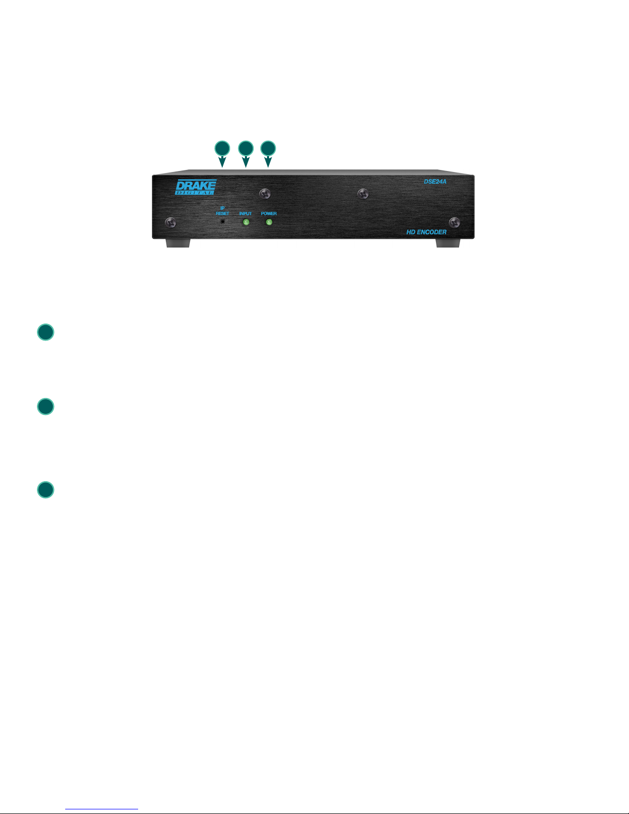
FRONT PANEL VIEW:
1 2 3
FRONT PANEL DESCRIPTION
1
IP Reset: When pressed for >10 seconds, the IP address of the control port will be enabled to the default factory
IP address (172.16.70.1, Subnet Mask 255.255.0.0). The login credentials will also be enabled to the default
username Admin and password pass, which are both case-sensitive.
Note: The old IP address, login, and password will still be present in the encoder settings. To clear the reset mode simply
reboot the encoder.
Status LED: indicates the status of input video and audio as follows:
2
Green = Both Video and Digital Audio inputs are present.
Red = Either the Video or Digital Audio is not present, or internal temperature is too high.
Note: The encoder does not sense analog audio inputs. Therefore, if the Audio is set for Analog, the status indicator will
only be valid for video.
3
Power LED: indicates if the unit is receiving power.
Green = power is detected.
Off = indicates (i) power is not connected, or (ii) power is connected but the power supply or encoder is
defective. The unit must be sent to the factory for repair for condition (ii).
8
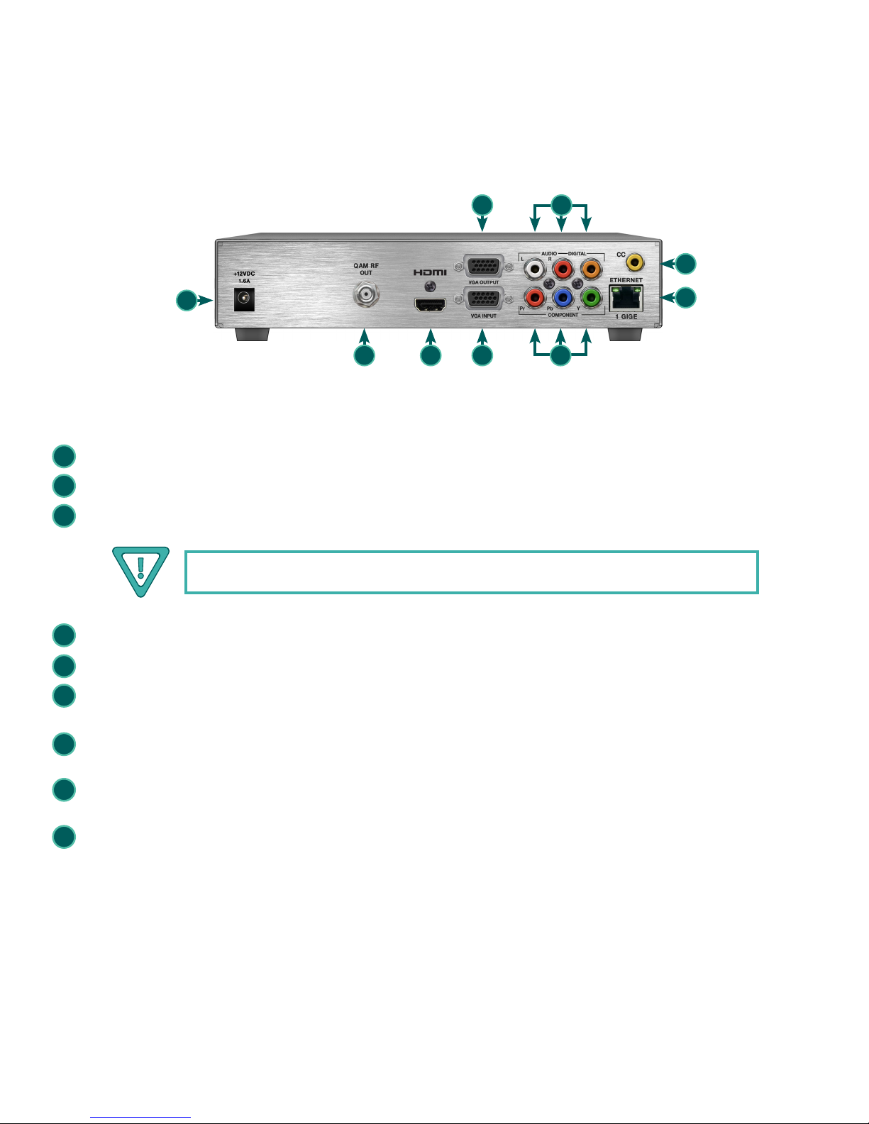
REAR PANEL VIEW:
Front and Rear Panel Operation
7 9
11
4
5 6 8
REAR PANEL DESCRIPTION
4
+12VDC, 1.6A: ITE power supply - rated 120VAC; 60Hz / Output 12VDC @ 3 Amp.
5
QAM RF Output: "F" Connector for QAM Output.
6
HDMI: HDMI connector for unencrypted HDMI input.
10
12
The DSE24A does not accept HDCP-Encrypted HDMI Input.
7
VGA Output: DE-15 female connector for loop-through VGA output.
VGA Input: DE-15 female connector for VGA input.
8
Audio: RCA connectors (marked: L and R) for Analog Left/Right Audio input and RCA connector (marked: DIGITAL)
9
for Digital Audio program input.
Component Out: RCA connectors (marked: Pr, Pb, Y) for Analog Component Video input. The RCA connector
10
(marked: Y) is also used for Composite Video input.
CC: RCA connector (marked “CC”) for Analog NTSC Closed Captioning (EIA-608, also known as Line 21), which
11
will then be digitized and inserted in the MPEG-2 Transport Stream of the Component, HDMI, and VGA inputs.
ETHERNET 1 GIGE: RJ45 connector for 100/1000Base-T Ethernet interface for monitoring and configuring the
12
unit. The same interface is used to deliver the IP output. Only static IP address can be assigned to this interface.
(Factory Default: "172.16.70.1")
9

Installation & Setup
Unpacking
You will find the following items in the box:
• DSE24A Encoder (QTY=1)
• Switching Mode Power Supply, 12 VDC, 3.0A (Item: 515132200)
• Cross Link Cable, 7 Ft (Item: 515102875 A)
Installation
The DSE24A encoder is designed for a desk/table top installation. An optional rack panel (stk#1002565A) allows two encoders to be
mounted in a 1RU.
You can mount the chassis in a standard EIA, 24 inch (610 mm) deep, enclosed rack. Secure the rack chassis front panel to the rack by
inserting four machine screws, with cup washers, through the four mounting holes in the front panel.
When installing units in a headend rack, it is recommended to leave a 1 rack unit space (1.75” high) between units to maximize air flow.
Power-Up
To power up the unit, connect the line cord of the external supply to a 120 VAC outlet.
The “POWER” LED on the front-panel will light green.
10
 Loading...