

Page 1
DSE 2 PLUS
Dual HD Digital Signage Encoder
INSTRUCTION MANUAL
Model Item # Description
DSE 2 PLUS 1002583 HD Encoder with QAM Output
937-746-4556
www.rldrake.com
© 2015 R.L. Drake Holdings, LLC.
Rev: 031915 P/N 651232800B
Page 2

We recommend that you write the following information in the spaces provided below.
Purchase Location Name:
Purchase Location Telephone Number:
DSE 2 PLUS Serial Number:
This product incorporates copyright protection technology that is protected by U.S. patents and other
intellectual property rights. Reverse engineering or disassembly is prohibited.
2
937.746.4556 | www.rldrake.com
Page 3

Table of Contents
CAUTION STATEMENTS ......................................................................................................................................................... 4
IMPORTANT SAFETY INSTRUCTIONS ................................................................................................................................. 4
SPECIFICATIONS .................................................................................................................................................................... 6
INSTALLATION & POWER-UP ................................................................................................................................................ 7
GENERAL DESCRIPTION & FEATURES ............................................................................................................................... 8
REAR PANEL OPERATION ..................................................................................................................................................... 9
LOGIN SCREEN ...................................................................................................................................................................... 10
STATUS TAB ............................................................................................................................................................................11
ENCODER TAB ....................................................................................................................................................................... 12
CHANNELS TAB ..................................................................................................................................................................... 13
OUTPUT CONFIGURATION TAB ........................................................................................................................................... 14
SYSTEM CONFIGURATION TAB ........................................................................................................................................... 14
FIRMWARE UPDATE TAB ...................................................................................................................................................... 15
CATV CHANNEL FREQUENCIES .......................................................................................................................................... 16
BROADCAST TV & T CHANNEL FREQUENCIES ............................................................................................................... 17
SERVICE .................................................................................................................................................................................. 18
WARRANTY ............................................................................................................................................................................. 19
937.746.4556 | www.rldrake.com
3
Page 4
Caution Statements
DSE 2 PLUS | 2
Instruction Manual
Rev: 20140
Table of Contents
IMPORTANT SAFETY INSTRUCTIONS ...................................................................................................................................................... 2
SPECIFICATIONS ............................................................................................................................................................................................ 4
GENERAL DESCRIPTION .............................................................................................................................................................................. 6
FEATURES ........................................................................................................................................................................................................ 6
INSTALLATION AND MOUNTING .............................................................................................................................................................. 6
REAR PANEL CONNECTIONS ..................................................................................................................................................................... 7
ETHERNET ACCESS ....................................................................................................................................................................................... 8
SETUP AND PROGRAMMING ................................................................................................................................................................... 10
FIRMWARE UPDATE .................................................................................................................................................................................... 15
SERVICE / IF YOU NEED TO CALL FOR HELP ........................................................................................................................................ 18
WARRANTY .............................................................................................................................................................................................................. 19
DSE 2 PLUS | 3
Instruction Manual
product. Any mounting of the product should follow the manufacturer's instructions, and should use a mounting accessory recommended by the
manufacturer.
9.
A product and cart combination should be moved with care. Quick stops, excessive force, and uneven surfaces may cause the product and cart combination
to overturn.
10.
Ventilation: Slots and openings in the cabinet are provided for ventilation and to ensure reliable operation of the product and to protect it from overheating,
and these openings must not be blocked or covered. The openings should never be blocked by placing the product on a bed, sofa, rug, or similar
surface. This product should not be placed in a built-in installation such as bookcase or rack unless proper ventilation is provided or the manufacturer's
instructions have been adhered to.
11.
Power Sources: This product should be operated only from the type of power source indicated on the marking label. If you are not sure of the type of power
supplied to your home, consult your product dealer or local power compan y. For products intended to operate from battery power, or other sources, refer to the
product's operating instructions.
12.
Grounding or Polarization: This product may be equipped with a polarized alternating-current line plug (a plug having one blade wider than the
other). This plug will fit into the power outlet only one way. This is a safety feature. If you are unable to
insert the plug fully into the outlet, try reversing
the plug. If the plug should still fail to fit, contact your electrician to replace your obsolete outlet. Do not defeat the safety purpose of the polarized
plug. Alternate Warnings – If this product is equipped with a three-wire grounding- type plug, a plug having a third (grounding) pin, the plug will only fit
into a grounding-type power outlet. This is a safety feature. If you are unable to insert the plug into the outlet, contact your electrician to replace your
obsolete outlet. Do not defeat the safety purpose of the grounding-type plug.
DSE 2 PLUS | 2
Instruction Manual
Rev: 20140
Table of Contents
IMPORTANT SAFETY INSTRUCTIONS ...................................................................................................................................................... 2
SPECIFICATIONS ............................................................................................................................................................................................ 4
GENERAL DESCRIPTION .............................................................................................................................................................................. 6
FEATURES ........................................................................................................................................................................................................ 6
INSTALLATION AND MOUNTING .............................................................................................................................................................. 6
REAR PANEL CONNECTIONS ..................................................................................................................................................................... 7
ETHERNET ACCESS ....................................................................................................................................................................................... 8
SETUP AND PROGRAMMING ................................................................................................................................................................... 10
FIRMWARE UPDATE .................................................................................................................................................................................... 15
SERVICE / IF YOU NEED TO CALL FOR HELP ........................................................................................................................................ 18
WARRANTY .............................................................................................................................................................................................................. 19
Caution Statements:
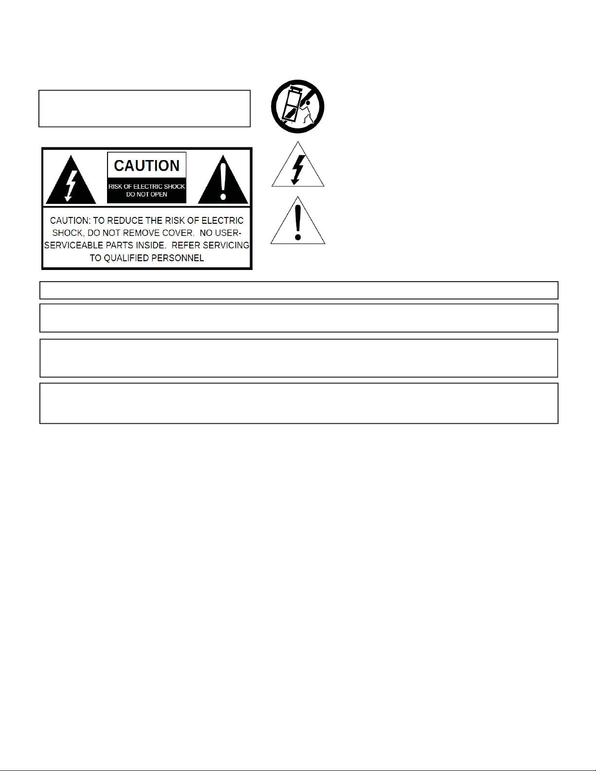
WARNING:
TO PREVENT FIRE OR ELECTRICAL
SHOCK, DO NOT EXPOSE TO RAIN
OR MOISTURE.
A product and cart combination should be moved
with care.
Quick stops, excessive force and uneven surfaces may
cause the product and cart combination to overturn.
The lightning flash with arrow head symbol, within an
equilateral
triangle, is intended to alert the user to
the presence of uninsulated "dangerous voltage"
within the product's enclosure
that may be of
sufficient magnitude to constitute a risk of electric
shock to persons.
The exclamation point within an equilateral triangle
is intended to alert the user to the presence of
important operating and maintenance (servicing)
instructions in the literature
accompanying the
product.
WARNING: THE SOCKET-OUTLET SHALL BE INSTALLED NEAR THE EQUIPMENT AND SHALL BE EASILY A CCESSIBLE.
WARNING: TO REDUCE THE RISK OF FIRE OR
ELECTRIC SHOCK, DO NOT EXPOSE THIS PRODUCT TO RAIN OR
MOISTURE. DO NOT OPEN THE CABINE T, REFER SERVICING TO QUALIFIED PERSONNEL ONLY.
CAUTION: TO PREVENT ELECTRIC SHOCK, DO NOT USE THIS (POLARIZED) PLUG WITH AN EXTENSION CORD
RECEPTACLE OR OTHER OUTLET UNLESS THE BLADES CAN BE FULLY INSERTED TO PREVENT BLADE
EXPOSURE.
ATTENTION: POUR PREVENIR LES CHOCS ELECTRIQUES , NE PA S UTILISER CETTE FICHE POLARISEE AVEC UN
PROLONGATEUR, UNE PRISE DE COURANT OU UNE AUTRE SORTIE DE COURANT, SAUF SI LES LAMES
PEUVENT ETRE INSEREES A FOND SANS EN LAISSER AUCUNE PA R TIE A DECOUVER T.
Important Safety Instructions:
1.
Read Instructions: All the safety and operating instructions should be read before the product is operated.
2.
Retain Instructions: The safety and operating instructions should be retained for future reference.
3.
Heed Warnings: All warnings on the product and in the operating instructions should be adhered to.
4.
Follow Instructions: All operating and use instructions should be followed.
5.
Cleaning: Unplug this product from the wall outlet before cleaning. Do not use liquid cleaners or aerosol cleansers. Use a damp cloth for cleaning.
6.
Attachments: Do not use attachments that are not recommended by the product manufacturer as they may cause hazards.
7.
Water and Moisture: Do not use this product near water—for example, near a bathtub, wash bowl, kitchen sink or laundry tub; in a wet basement;
or near a swimming pool; and the like.
8.
Accessories: Do not place this product on an unstable cart, stand, tripod, bracket, or table. The product may fall, causing serious injury to a child or
adult, and serious damage to the product. Use only with a cart, stand, tripod, bracket, or table recommended by the manufacturer, or sold with the
Caution Statements:
A product and cart combination should be moved
WARNING:
SHOCK, DO NOT EXPOSE TO RAIN
TO PREVENT FIRE OR ELECTRICAL
OR MOISTURE.
with care.
Quick stops, excessive force and uneven surfaces may
cause the product and cart combination to overturn.
The lightning flash with arrow head symbol, within an
equilateral
the presence of uninsulated "dangerous voltage"
within the product's enclosure
sufficient magnitude to constitute a risk of electric
shock to persons.
The exclamation point within an equilateral triangle
is intended to alert the user to the presence of
important operating and maintenance (servicing)
instructions in the literature
product.
triangle, is intended to alert the user to
accompanying the
that may be of
WARNING: THE SOCKET-OUTLET SHALL BE INSTALLED NEAR THE EQUIPMENT AND SHALL BE EASILY ACCESSIBLE.
WARNING: TO REDUCE THE RISK O F FIRE OR ELECTRIC SHOCK, DO NOT EXPOSE THIS PRODUCT TO RAIN OR
MOISTURE. DO NOT OPEN THE CABINE T, REFER SERVICING TO QUALIFIED PERSONNEL ONL Y.
CAUTION: TO PREVENT ELECTRIC SHOCK, DO NOT USE THIS (POLARIZED) PLUG WITH AN EXTENSION CORD
RECEPTACLE OR OTHER OUTLET UNLESS THE BLADES CAN BE FULLY INSERTED TO PREVENT BLADE
EXPOSURE.
ATTENTION: POUR PREVENIR LES CHOCS ELECTRIQUES, NE PAS UTILISER CETTE FICHE POLARISEE AVEC UN
PROLONGATEUR, UNE PRIS
E DE COURANT OU UNE AUTRE SORTIE DE COURANT, SAUF SI LES LAMES
PEUVENT ETRE INSEREES A FOND SANS EN LAISSER AUCUNE PAR TIE A DECOUVERT.
Important Safety Instructions
4
937.746.4556 | www.rldrake.com
Page 5
Safety Instructions continued...
DSE 2 PLUS | 3
Instruction Manual
product. Any mounting of the product should follow the manufacturer's instructions, and should use a mounting accessory recommended by the
manufacturer.
9.
A product and cart combination should be moved with care. Quick stops, excessive force, and uneven surfaces may cause the product and cart combination
to overturn.
10.
Ventilation: Slots and openings in the cabinet are provided for ventilation and to ensure reliable operation of the product and to protect it from overheating,
and these openings must not be blocked or covered. The openings should never be blocked by placing the product on a bed, sofa, rug, or similar
surface. This product should not be placed in a built-in installation such as bookcase or rack unless proper ventilation is provided or the manufacturer's
instructions have been adhered to.
11.
Power Sources: This product should be operated only from the type of power source indicated on the marking label. If you are not sure of the type of power
supplied to your home, consult your product dealer or local power compan y. For products intended to operate from battery power, or other sources, refer to the
product's operating instructions.
12.
Grounding or Polarization: This product may be equipped with a polarized alternating-current line plug (a plug having one blade wider than the
other). This plug will fit into the power outlet only one way. This is a safety feature. If you are unable to
insert the plug fully into the outlet, try reversing
the plug. If the plug should still fail to fit, contact your electrician to replace your obsolete outlet. Do not defeat the safety purpose of the polarized
plug. Alternate Warnings – If this product is equipped with a three-wire grounding- type plug, a plug having a third (grounding) pin, the plug will only fit
into a grounding-type power outlet. This is a safety feature. If you are unable to insert the plug into the outlet, contact your electrician to replace your
obsolete outlet. Do not defeat the safety purpose of the grounding-type plug.
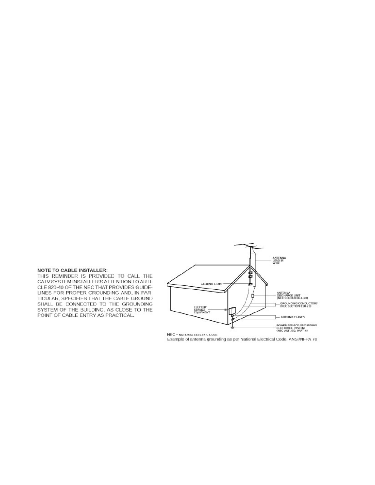
13.
Outdoor Antenna Grounding: If an outside antenna or cable system is connected to the product, be sure the antenna or cable system is
grounded so as to provide some protection against voltage surges and built-up static charges. Ar ticle 810 of the National Electrical Code,
ANSI/NFPA 70, provides information with regard to proper grounding of the mast and supporting structure, grounding of the lead-in wire
to an antenna discharge unit, size of grounding conductors, location of antenna-discharge unit, connection to grounding electrodes, and
requirements for the grounding electrode.
14.
Power-Cord Protection: Power-supply cords should be routed so that they are not likely to be walked on or pinched by items placed upon or against them,
paying particular attention to cords at plugs, convenience receptacles, and the poin
t where they exit from the product.
15.
Lightning: For added protection for this product during a lightning storm, or when it is left unattended and unused for long periods of time, unplug it
from the wall outlet and disconnect the antenna or cable system. This will prevent damage to the product due to lightning and power-line surges.
16.
Power Lines: An outside antenna system should not be located in the vicinity of overhead power lines, other electric light or power circuits, where it
can fall into such power lines or circuits. When installing an outside antenna system, extreme care should be taken to keep from touching such power
lines or circuits as contact with them may be fatal.
17.
Overloading: Do not overload wall outlets, extension cords, or integral convenience receptacles as this can result in a risk of fire or electric shock.
18.
Object and Liquid Entry: Never push objects of any kind into this product through openings as they may touch dangerous voltage points or short-out
parts that could result in a fire or electric shock. Never spill liquid of any kind on the product.
19.
Servicing: Do not attempt to service this product yourself as opening or removing covers may expose you to dangerous voltage or other hazards.
Refer all ser
vicing to qualified service personnel.
20.
Damage Requiring Service: Unplug this product from the wall outlet and refer servicing to qualified service personnel under the following conditions:
a) When the power-supply cord or plug is damaged,
b) If liquid has been spilled, or objects have fallen into the product,
c) If the product has been exposed to rain or wate r,
d) If the product does not operate normally by following the operating instructions.
Adjust only those controls that are cove red by the operating instructions as an improper adjustment of other controls may result in damage and will
often require extensive work by a qualified technician to restore the product to its normal operation, e. If the product has been dropped or damaged
in any way, and f. When the product exhibits a distinct change in performance—this indicates a need for service.
21.
Replacement Parts: When replacement parts are required, be sure the service technician has used replacement parts specified by the manufacturer
or have the same characteristics as the original part. Unauthorized substitutes may result in fire, electric shock or other hazards.
22.
Safety Check: Upon completion of any service or repairs to this product, ask the service technician to perform safety checks to determine that the
product is in proper operating condition.
23.
Wall or Ceiling Mounting: The product should be mounted to a wall or ceiling only as recommended by the manufacturer.
937.746.4556 | www.rldrake.com
5
Page 6

Specifications
ENCODER - VIDEO (Specicaons are per Encoder)
Video Inputs: VGA (with pass-through to monitor),
HDMI (non-HDCP Copy Protected),
Component (Y-Cr-Cb),
Composite (via Y-Input for 480i)
Video Resoluon Modes: 480i (640x480 / 720x480 @ 30 fps),
480p (640x480 / 720x480 @ 60 fps),
720p (1280x 720 @ 60 fps),
1080i (1920x1080 @ 30 fps)
Video Input Resoluon Detecon: Yes, automac
Video Compression Format: MPEG2 or MPEG4 / H.264
Video Adjustments: Brightness, Contrast, Hue, Saturaon, Sharpness
MPEG4 / H.264 Proles Supported: Simple, Advanced Simple, High
Bitrate: 0.000 to 19 Mbps (depending on format)
ENCODER - AUDIO (Specicaons are per Encoder)
Audio Inputs: HDMI-embedded audio, 32 - 192 kHz sample rate PCM
RCA-type L + R 1 x 1 Vrms nominal
3.5 Vrms max supports +/- 15 dB gain adjustment
Audio Compression Formats: Dolby® Digital or MPEG1, Layer 2
QAM (Quadrature Amplitude Modulaon) MODULATOR / MULTIPLEXER (per chassis)
QAM Output Modes: 64 QAM or 256 QAM, ITU Annex B
Frequency Coverage: 5 - 1002 MHz
Channel Plans: Standard CATV, HRC, IRC, Broadcast and T Channels
Maximum Output Power Level: + 45 dBmV
Level Adjustment Range: 15 dB
Phase Noise: - 95 dBc @ 10 kHz oset
Broadband Noise: - 75 dBc @ > +/- 12 MHz
MER: > 40 dB equalized
Channel Frequency Response: < 1 dB
Carrier Suppression: > 40 dB
I/Q Inbalance: < 1 degree
Output Level Accuracy: +/- 1 dB
QAM (Quadrature Amplitude Modulaon) MODULATOR / MULTIPLEXER (per chassis)
Form Factor: 1RU 19” rack mountable
Control: On-board Ethernet Connecon
Power Requirements: +5 V @ 3.5A via supplied external power supply
Dimensions: 10.5’’D x 2.0’’H x 19’’ W
Weight: 4.5 lbs.
Temperature Rang: 0 - 50˚ C ambient
Specifications, price, and availability are subject to change without notice or obligation.
6
937.746.4556 | www.rldrake.com
Page 7

Installation & Power-Up
DSE 2 PLUS | 2
Instruction Manual
Rev: 20140
A product and cart combination should be moved
with care.
Quick stops, excessive force and uneven surfaces may
cause the product and cart combination to overturn.
The lightning flash with arrow head symbol, within an
equilateral
triangle, is intended to alert the user to
the presence of uninsulated "dangerous voltage"
within the product's enclosure
that may be of
sufficient magnitude to constitute a risk of electric
shock to persons.
The exclamation point within an equilateral triangle
is intended to alert the user to the presence of
important operating and maintenance (servicing)
instructions in the literature
accompanying the
Unpacking
You will find the following items in the box:
• DSE 2 PLUS Encoder Unit (QTY = 1)
• Power Adapter (QTY = 1)
Installation
The DSE 2 PLUS is designed to be 1RU 19" rack mountable in the close proximity to a 120 VAC – 60 HZ power plug.
For safe and reliable operation, do not place objects within 1 inch of the unit that block airflow.
Power-Up
Plug the Power Adapter into a power plug (120 VAC – 60 HZ). Plug the power pin into the back of the DSE unit at the
input marked “DC Power”.
For safe and reliable operation, only use the power adapter supplied with the encoder.
937.746.4556 | www.rldrake.com
7
Page 8

General Description & Features
The DSE 2 PLUS encodes up to two uncompressed programs from devices with HDMI (non HDCP encrypted), HighResolution Component Video, Composite or VGA outputs. The DSE 2 PLUS encodes the incoming programs to MPEG-2
or MPEG-4/H.264 compressed video. An internal multiplexing QAM modulator and low-noise upconverter allows programs
to be combined with existing digital and or analog programming.
• Encodes a HD & SD stream of the same content in either MPEG-2 or H.264 formats
• Receives High-Resolution Component, VGA, or HDMI (non-HDCP content-protection) from two separate video sources.
• Video encodes to MPEG-2 or MPEG-4/H.264
• Supports 480i, 480p, 720p, or 1080i video resolution
• Audio encoding to Dolby Digital® or MPEG1-Layer 2
• Supports Closed Captioning
• High-level (+45 dBmV) agile output programmable from 5 to 1,000 MHz using STD, HRC, IRC, and
Broadcast channel plans
• GUI-based Remote Network Control and Monitoring
8
937.746.4556 | www.rldrake.com
Page 9

Rear Panel Operation
6 12
7 8 1413
1 2 4 53 9 10 11 15 16 17
RF Output: This type “F” connector is a high level (+29.5 dBmV to +45 dBmV), agile 5 to 1002 MHz, multiplexed
1
output from the DSE2 Plus RF output section.
DC Power Connector: This connector provides the means for connection to the 5 VDC output of the supplied external
2
power supply.
Component Input 2: These three color coded RCA connectors, Cr (red), Cb (blue), and Y (green), provide the means
3
to input component video. To input composite video, use the green ‘Y’ connector.
4
VGA Input 2: This VGA type connector provides the means to input VGA video from a computer or other device with
VGA output.
HDMI Input 2: This connector provides the means to input HDMI video (without HDCP) with optional embedded audio.
5
Audio Input 2: These two color coded RCA vtype connectors provide baseband audio Left (white) and Right (red)
6
inputs to the DSE2 Plus.
7
Closed Caption Input 2: This connector provides the means to input closed captioning. It requires analog composite
video that contains closed captioning.
VGA Loop Output 2: This connector provides VGA video output to a monitor or other equipment requiring VGA input.
8
It is only active when VGA is input on R4.
Component Input 1: These three color coded RCA connectors, Cr (red), Cb (blue), and Y (green), provide the means
9
to input component video. To input composite video, use the green ‘Y’ connector.
VGA Input 1: This VGA type connector provides the means to input VGA video from a computer or other device with
10
VGA output.
11
HDMI Input 1: This connector provides the means to input HDMI video (without HDCP) with optional embedded audio.
12
Audio Input 1: These two color coded RCA type connectors provide baseband audio Left (white) and Right (red)
inputs to the DSE2 Plus.
Closed Caption Input 1: This connector provides the means to input closed captioning. It requires analog composite
13
video that contains closed captioning.
VGA Loop Output 1: This connector provides VGA video output to a monitor or other equipment requiring VGA input.
14
It is only active when VGA is input on R10.
Status LED: Ethernet Link indicator.
15
16
IP Reset: When pushed and held for about 10 seconds, resets the IP address, Usernames, and Passwords to Factory
default values.
Ethernet Connection: This connector provides the means to connect the DSE2 Plus to an Ethernet local area
17
network or computer for remote control, monitoring, and/or firmware update. It is not recommended that this port be
connected directly to a wide-area network without external access controls, like a VPN or firewall.
937.746.4556 | www.rldrake.com
9
Page 10

Login Screen
First, connect the appropriate input and output video cables and plug in the DSE 2 PLUS power cable.
ETHERNET ACCESS:
Local or remote communication with the unit is only possible through a GUI-based menu via any standard web browser
(Chrome or Firefox recommended). Before you can communicate with the unit you must configure your computers Local
Area Network connection to confirm with the DSE 2 Plus default IP of 172.16.80.1. To do so, follow these steps:
Connect an Ethernet cable from your computer to the Ethernet connection on the rear panel of the DSE 2 Plus.
1. The following steps explain how to do this for a computer with windows XP operating software:
a) On your computer, open the "Control Panel"
b) Double-click on "Network Connections"
c) Right-click on the "Local Area Connection", and then click on the "properties".
A dialog box entitled "Local Area Connection Properties" will appear. In this box, double-click on the "Internet
d)
Protocol (TCP/IP)".
A dialog box entitled "Internet Protocol (TCP/IP) Properties" will appear. Select the "Use the following IP address"
e)
option and enter the following addresses:
IP address: 172.16.80.2
Subnet mask: 255.255.255.0
No need to enter a value for the Default Gateway.
Click OK to close the dialog box. Now your computer is ready to communicate with the unit.
2. The following steps explain how to do this for a computer with windows 7 operating software:
a) On your computer, open the "Control Panel"
b) Click on “Network and Internet”
c) Click on the "View network status and tasks"
Click on “Change Adapter Settings” on left hand side of the window
d)
e) Right-click on the "Local Area Connection", and then click on the "Properties".
f) A dialog box entitled "Local Area Connection Properties" will appear. In this box, double-click on the "Internet
Protocol Version 4 (TCP/IPv4)".
A dialog box entitled "Internet Protocol Version 4 (TCP/IPv4) Properties" will appear. Select the "Use the following
g)
IP address" option and enter the following addresses:
IP address: 172.16.80.2
Subnet mask: 255.255.255.0
No need to enter a value for the Default Gateway.
Click OK.
Open a web browser on your computer (Internet Explorer 7 or higher is recommended) and enter the following URL
address (http://172.16.80.1). Once the DSE 2 Plus web server has been loaded from your browser, you should see the
login dialog (see Figure 1). Enter the username and password and click LOG IN. The default username is "admin" (in
lower case letters) and the default password is "pass" (in lower case letters).
10
937.746.4556 | www.rldrake.com
Page 11

Status Tab
The status tab provides the following information (View only):
1
2
The hardware version indicates the hardware version of the DSE 2 Plus
1
The Uptime of the unit (days, hours, minutes, and seconds), which can be set on the System tab under Unit
2
Description.
937.746.4556 | www.rldrake.com
11
Page 12

Encoders Tab
The Encoders tab allows you to set each encoder's individual parameters. Select an encoder module from the drop-down
menu and the appropriate setting selections will be displayed.
12
937.746.4556 | www.rldrake.com
Page 13

Channels Tab
The Channels tab provides an interface to configure the virtual channel mappings for this encoder host. If PSIP is
enabled, this page will display a screen that looks as shown below; for each encoder output, the MPEG program number
can be modified, along with the Major and Minor channel numbers. If one-part virtual channel numbers are desired, the
PSIP Mode must be set to CVCT and the Minor number for each channel should be set to 0.
937.746.4556 | www.rldrake.com
13
Page 14

Output Configuration Tab
The Output tab provides an interface to set all modulator output settings for the unit.
System Configuration Tab
The System Tab allows you to set a unique IP address for remote access and monitoring. Pressing the rear panel IP
reset button will enable the default IP 172.16.80.1. The unique IP address previously set will also be retained.
14
937.746.4556 | www.rldrake.com
Page 15

Firmware Update Tab
This tab uploads the newest available firmware for the DSE 2 PLUS and deploys firmware to the unit. While the firmware
update tab is actively updating; the logging information and instructions are provided. When the update is completed, the
unit will automatically reboot.
937.746.4556 | www.rldrake.com
15
Page 16

CATV Channel Frequencies
CABLE TV CHANNELS
Channel
Number
EIA/NCTA
Equivalent
2
3
4
5
6
95
96
97
98
99
14
15
16
17
18
19
20
21
22
7
8
9
10
11
12
13
23
24
25
26
27
28
29
30
31
32
33
34
35
36
37
Center of
Channel
Frequency
(MHz)
57
63
69
79
85
93
99
105
111
117
123
129
135
141
147
153
159
165
171
177
183
189
195
201
207
213
219
225
231
237
243
249
255
261
267
273
279
285
291
297
303
CABLE TV CHANNELS
Channel
Number
EIA/NCTA
Equivalent
38
39
40
41
42
43
44
45
46
47
48
49
50
51
52
53
54
55
56
57
58
59
60
61
62
63
64
65
66
67
68
69
70
71
72
73
74
75
76
77
78
79
80
Center of
Channel
Frequency
(MHz)
309
315
321
327
333
339
345
351
357
363
369
375
381
387
393
399
405
411
417
423
429
435
441
447
453
459
465
471
477
483
489
495
501
507
513
519
525
531
537
543
549
555
561
CABLE TV CHANNELS
Channel
Number
EIA/NCTA
Equivalent
81
82
83
84
85
86
87
88
89
90
91
92
93
94
100
101
102
103
104
105
106
107
108
109
110
111
112
113
114
115
116
117
118
119
120
121
122
123
124
125
Center of
Channel
Frequency
(MHz)
567
573
579
585
591
597
603
609
615
621
627
633
639
645
651
657
663
669
675
681
687
693
699
705
711
717
723
729
735
741
747
753
759
765
771
777
783
789
795
801
CABLE TV CHANNELS
Channel
Number
EIA/NCTA
Equivalent
126
127
128
129
130
131
132
133
134
135
136
137
138
139
140
141
142
143
144
145
146
147
148
149
150
151
152
153
154
155
156
157
158
Center of
Channel
Frequency
(MHz)
807
813
819
825
831
837
843
849
855
861
867
873
879
885
891
897
903
909
915
921
927
933
939
945
951
957
963
969
975
981
987
993
999
16
937.746.4556 | www.rldrake.com
Page 17

Broadcast TV & T Channel Frequencies
VHF BROADCAST CHANNELS
Channel
Number
2
3
4
5
6
7
8
9
10
11
12
13
Center of Channel
Frequency (MHz)
57
63
69
79
85
177
183
189
195
201
207
213
T CHANNELS
Channel
Number
7
8
9
10
11
12
13
14
Center of Channel
Frequency (MHz)
8.75
14.75
20.75
26.75
32.75
38.75
44.75
50.75
UHF BROADCAST CHANNELS
Channel
Number
14
15
16
17
18
19
20
21
22
23
24
25
26
27
28
29
30
31
32
33
34
35
36
37
38
39
40
41
42
43
44
45
46
47
48
49
50
51
52
53
54
55
56
57
58
59
60
61
62
63
64
65
66
67
68
69
Center of Channel
Frequency (MHz)
473
479
485
491
497
503
509
515
521
527
533
539
545
551
557
563
569
575
581
587
593
599
605
611
617
623
629
635
641
647
653
659
665
671
677
683
689
695
701
707
713
719
725
731
737
743
749
755
761
767
773
779
785
791
797
803
937.746.4556 | www.rldrake.com
17
Page 18

SERVICE INFORMATION
23
A Return Material Authorization (RMA) Number is required on ALL PRODUCT RETURNS (regardless of wheth-
Service / If You Need To Call For Help
er the product is being returned for repair or for credit). Product that is received at the factory without an RMA
Number will be returned to the Sender, unopened.
RMA Numbers must be used when returning product for credit or repair. Use of RMA Numbers will ensure
efficient processing. When needing to return your product to R.L. Drake Holdings, LLC., please follow these
SERVICE REPAIRS ONLY CREDIT RETURNS ONLY
1. Contact R.L. Drake Holdings, LLC.’s Service Department 1. Contact R.L. Drake Holdings, LLC.’s Service Department
2. Request from Drake Service a copy of the Product Return 2. Request from Drake Service a copy of the Product Return
3. Complete the Product Return Authorization Form fully. 3. Complete the Product Return Authorization Form fully.
4. Return the completed Product Return Authorization Form 4. Return the completed Product Return Authorization Form
simple s
teps listed below (in the order that they appear).
in one of three ways: in one of three ways:
A. Phone: 937-746-6990 A. Phone: 937-746-6990
B. Email: servicehelp@rldrake.com B. Email: servicehelp@rldrake.com
C. Fax: 937-806-1510 C. Fax: 937-806-1510
Authorization Form. Authorization Form
to the Drake Service Department using one of the contact to the Drake Service Department using one of the contact
methods listed in Step 1. methods listed in Step 1.
Service
.
5. After completing Steps 1 through 4, an RMA Number will 5. After completing Steps
be assigned to you. be assigned to you.
6. Securely pack the product and mark the box with your RMA 6. Securely pack the product in its original undamaged box
Number. If shipping multiple boxes, all boxes must be mark- (returning the product without its original packaging in good,
ed with the RMA Number. Place the RMA Number near the new condition may cause the incursion of additional fees).
return address in large, bold print (approx. 2” in height). Pack this box
Mark the shipping box or container with your RMA Number.
Place the RMA Number near the return address in large,
bold print (approx. 2” in height).
7. Ship your “SERVICE REPAIR ONLY” return to: 7. Ship your “CREDIT RETURNS ONLY” return to:
R.L. Drake Holdings, LLC.
Attn: Product Service Returns
One Jake Brown Road
Old Bridge, NJ 08857
R.L. Drake Holdings, LLC.
Attn: Product Credit Returns
One Jake Brown Road
Old Bridge, NJ 08857
within another shipping container or box.
1 through 4, an RMA Number will
*NOTE: All Credit Returns are subject to a 15% Restock Fee
*NOTE: All shipments are to be PRE-
IF YOU NEED TECHNICAL HELP
Call our Customer Service/Technical Support line at +1 (937) 746-6990 between 8:00 A.M. and 4:00 P.M. Eastern Standard Time, weekdays. Please have the unit’s serial number available. We will also need to know the specifics of any
other equipment connected to the unit. When calling, please have the unit up and running, near the phone if possible.
Our technician(s) will likely ask cert
possible.
ain questions to aid in diagnosis of the problem. Also, have a voltmeter handy, if at all
PAID by the sender. NO COD’s will be accepted.
DRAKE also provides technical assistance by Email: servicehelp@rldrake.com
Fax: (937) 806-1510.
Many of the products that are sent to us for repair are in perfect working order when we receive them. For these units,
there is a standard checkout fee that will be charged. Please perform whatever steps are applicable from the product’s Instruction Manual before ca
without calling Drake Service and following the steps above first; it is preferred to help troubleshoot the problem over the
phone (or by Email) first, saving you both time and money.
18
937.746.4556 | www.rldrake.com
lling or writing - this could save unnecessary phone charges. Please do not return the product
Page 19

Limited Warranty
THREE YEAR LIMITED WARRANTY
R.L. DRAKE LLC warrants to the original purchaser this product shall be free from defects in material or workmanship for
three (3) years from the date of original purchase.
During the warranty period the R.L. DRAKE LLC or an authorized Drake service facility will provide, free of charge, both
parts and labor necessary to correct defects in material and workmanship. At its option, R.L. DRAKE LLC may replace a
defective unit.
To obtain such a warranty service, the original purchaser must:
(1) Retain invoice or original proof of purchase to establish the start of the warranty period.
(2) Notify the R.L. DRAKE LLC or the nearest authorized service facility, as soon as possible after discovery of a
possible defect, of:
(a) the model and serial number,
(b) the identity of the seller and the approximate date of purchase; and
(c) A detailed description of the problem, including details on the electrical connection to associated
equipment and the list of such equipment.
(3) Deliver the product to the R.L. DRAKE LLC or the nearest authorized service facility, or ship the same in its
original container or equivalent, fully insured and shipping charges prepaid.
Correct maintenance, repair, and use are important to obtain proper performance from this product. Therefore carefully
read the Instruction Manual. This warranty does not apply to any defect that R.L. DRAKE LLC determines is due to:
(1) Improper maintenance or repair, including the installation of parts or accessories that do not conform to the
qualityandspecicationsoftheoriginalparts.
(2) Misuse, abuse, neglect or improper installation.
(3) Accidental or intentional damage.
Allimpliedwarranties,ifany,includingwarrantiesofmerchantabilityandtnessforaparticularpurpose,terminatethree
(3) years from the date of the original purchase.
The foregoing constitutes R.L. DRAKE LLC's entire obligation with respect to this product, and the original purchaser shall
have no other remedy and no claim for incidental or consequential damages, losses or expenses. Some states do not
allow limitations on how long an implied warranty lasts or do not allow the exclusions or limitation of incidental or consequential damages, so the above limitation and exclusion may not apply to you.
Thiswarrantygivesyouspeciclegalrightsandyoumayalsohaveotherrightswhichvaryfromstatetostate.
This warranty shall be construed under the laws of Ohio.
For Service, contact:
R. L. DRAKE HOLDINGS LLC
710PleasantValleyDrive
Springboro,OH45066
Customer Service and Parts: (937) 746-6990
Fax: (937) 806-1576
Email: servicehelp@rldrake.com
Web Site: www.rldrake.com
937.746.4556 | www.rldrake.com
19
Page 20

R.L. DRAKE HOLDINGS, LLC
Sales: 937-746-4556 • Support: 937-746-6990 • Fax: 937-806-1510
www.rldrake.com
 Loading...