

As of the FIRMWARE VERSION installed on this DNP100 is:
/ / _________
DNP100
DRAKE NETWORK PLAYER
Stand-alone or Network-controlled HD Video Media Player
INSTRUCTION MANUAL
is a registered trademark of R.L. Drake Holdings, LLC
© Copyright 2013 R. L. Drake Holdings, LLC P/N: 651233300 Printed in U.S.A.
V007 12172013
1002584
As of the FIRMWARE VERSION installed on this DNP100 is:
/ / _________
TABLE OF CONTENTS AND CAUTION STATEMENTS
TABLE OF CONTENTS AND CAUTION STATEMENTS ..................................................................................
IMPORTANT SAFETY INSTRUCTIONS ...........................................................................................................
Chapter 1 – THE DNP100 DRAKE NETWORK PLAYER ................................................................................
INTRODUCTION ....................................................................................................................................
CONNECTIONS .....................................................................................................................................
Chapter 2 – DRAKE DNP SERIES DIGITAL SIGNAGE MANAGER SOFTWARE (DSM) ..............................
DSM Main Window .................................................................................................................................
PLAYERS Tab ........................................................................................................................................
Chapter 3 - ADDING CONTENT ......................................................................................................................
VIDEOS Tab ..........................................................................................................................................
IMAGES Tab ..........................................................................................................................................
MUSIC (MP3) Tab .................................................................................................................................
Chapter 4 - CUSTOM AUTHORING IN DSM ...................................................................................................
CHANNELS Tab ....................................................................................................................................
PLAYLISTS Tab .....................................................................................................................................
LAYOUTS Tab .......................................................................................................................................
SCHEDULES Tab ..................................................................................................................................
Chapter 5 – LOADING PLAYLIST AND LAYOUT ..........................................................................................
LOAD / PLAY .........................................................................................................................................
PUBLISH TO USB DRIVE .....................................................................................................................
PUBLISH TO SD CARD ........................................................................................................................
Chapter 6 – RECOMMENDED SETTINGS ......................................................................................................
DSM - MONITOR AND VIDEO OUTPUT ..............................................................................................
PC - YOUR FIREWALL .........................................................................................................................
PC - DISABLING CHECKSUM OFFLOADING .....................................................................................
PC - HARDWARE REQUIREMENTS ...................................................................................................
Chapter 7 – DATA ............................................................................................................................................
SPECIFICATIONS .................................................................................................................................
TROUBLESHOOTING ..........................................................................................................................
LIMITED WARRANTY ...........................................................................................................................
SERVICE INFORMATION .....................................................................................................................
APPENDIX ........................................................................................................................................................
ACCESSORY REMOTE CONTROL .....................................................................................................
DCM ENTERPRISE MANAGEMENT SUITE FOR WINDOWS® .........................................................
GETTING STARTED ....................................................................................................................
2
3
5
5
6
7
8
9
9
13
14
15
16
17
17
19
22
28
30
30
31
31
33
33
33
35
35
36
36
37
38
39
A1
A1
A3
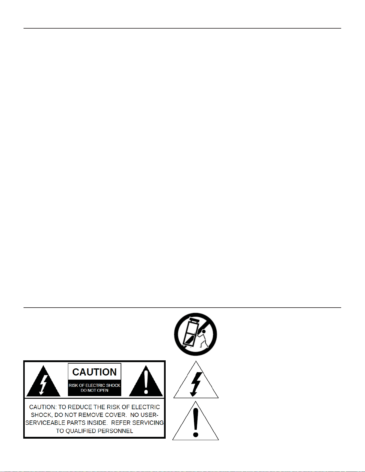
Caution Statements:
WARNING: TO PREVENT
A product and cart combination should be moved
with care. Quick stops, excessive force and
uneven surfaces may cause the product and cart
combination to overturn.
FIRE OR ELECTRICAL
SHOCK, DO NOT
The lightning flash with arrow head symbol,
within an equilateral triangle, is intended to
alert the user to the presence of uninsulated
"dangerous voltage" within the product's
enclosure that may be of sufficient magnitude to
constitute a risk of electric shock to persons.
The exclamation point within an equilateral
triangle is intended to alert the user to
the presence of important operating and
maintenance (servicing) instructions in the
literature accompanying the product.
***NOTE: Connect and apply power only after all other connections are made.***

IMPORTANT SAFETY INSTRUCTIONS
WARNING: TO REDUCE THE RISK OF FIRE OR ELECTRIC SHOCK, DO NOT EXPOSE THIS PRODUCT TO RAIN OR
MOISTURE.
DO NOT OPEN THE CABINET, REFER SERVICING TO QUALIFIED PERSONNEL ONLY.
CAUTION: TO PREVENT ELECTRIC SHOCK, DO NOT USE THIS (POLARIZED) PLUG WITH AN EXTENSION CORD
RECEPTACLE OR OTHER OUTLET UNLESS THE BLADES CAN BE FULLY INSERTED TO PREVENT BLADE
EXPOSURE
ATTENTION: POUR PREVENIR LES CHOCS ELECTRIQUES, NE PAS UTILISER CETTE FICHE POLARISEE AVEC UN
PROLONGATEUR, UNE PRISE DE COURANT OU UNE AUTRE SORTIE DE COURANT, SAUF SI LES LAMES
PEUVENT ETRE INSEREES A FOND SANS EN LAISSER AUCUNE PARTIE A DECOUVERT.
1. Read Instructions: All the safety and operating instructions should be read before the product is operated.
2. Retain Instructions: The safety and operating instructions should be retained for future reference.
3. Heed Warnings: All warnings on the product and in the Instruction Manualshould be adhered to.
4. Follow Instructions: All operating and use instructions should be followed.
5. Cleaning: Unplug this product from the wall outlet before cleaning. Do not use liquid cleaners or aerosol
cleansers. Use a damp cloth for cleaning.
6. Attachments: Do not use attachments that are not recommended by the product manufacturer as they
may cause hazards.
7. Water and Moisture: Do not use this product near water—for example, near a bathtub, wash bowl, kitchen
sink or laundry tub; in a wet basement; or near a swimming pool; and the like.
8. Accessories: Do not place this product on an unstable cart, stand, tripod, bracket, or table. The product
may fall, causing serious injury to a child or adult, and serious damage to the product. Use only with a cart,
stand, tripod, bracket, or table recommended by the manufacturer, or sold with the product. Any mounting
of the product should follow the manufacturer’s instructions, and should use a mounting accessory
recommended by the manufacturer.
.
9. A product and cart combination should be moved with care. Quick stops, excessive force, and uneven
surfaces may cause the product and cart combination to overturn.
10. Ventilation: Slots and openings in the cabinet are provided for ventilation and to ensure reliable operation
of the product and to protect it from overheating, and these openings must not be blocked or covered.
The openings should never be blocked by placing the product on a bed, sofa, rug, or similar surface. This
product should not be placed in a built-in installation such as bookcase or rack unless proper ventilation is
provided or the manufacturer’s instructions have been adhered to.
11. Power Sources: This product should be operated only from the type of power source indicated on the
marking label. If you are not sure of the type of power supplied to your home, consult your product dealer
or local power company. For products intended to operate from battery power, or other sources, refer to the
operating instructions.
12. Grounding or Polarization: This product may be equipped with a polarized alternating-current line plug
(a plug having one blade wider than the other). This plug will fit into the power outlet only one way. This
is a safety feature. If you are unable to insert the plug fully into the outlet, try reversing the plug. If the
plug should still fail to fit, contact your electrician to replace your obsolete outlet. Do not defeat the safety
purpose of the polarized plug. Alternate Warnings – If this product is equipped with a three-wire groundingtype plug, a plug having a third (grounding) pin, the plug will only fit into a grounding-type power outlet. This
is a safety feature. If you are unable to insert the plug into the outlet, contact your electrician to replace
your obsolete outlet. Do not defeat the safety purpose of the grounding-type plug.
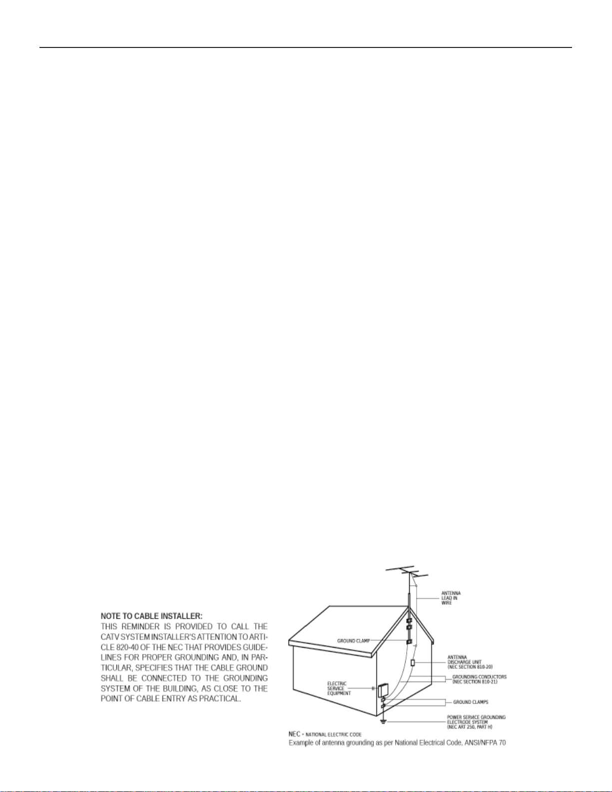
13. Outdoor Antenna Grounding: If an outside antenna or cable system is connected to the product, be
sure the antenna or cable system is grounded so as to provide some protection against voltage surges and
built-up static charges. Article 810 of the National Electrical Code, ANSI/NFPA 70, provides information
with regard to proper grounding of the mast and supporting structure, grounding of the lead-in wire to an
antenna discharge unit, size of grounding conductors, location of antenna-discharge unit, connection to
grounding electrodes, and requirements for the grounding electrode.
14. Power-Cord Protection: Power-supply cords should be routed so that they are not likely to be walked on
or pinched by items placed upon or against them, paying particular attention to cords at plugs, convenience
receptacles, and the point where they exit from the product.
(continued on Page 4)
4
15. Lightning: For added protection for this product during a lightning storm, or when it is left
unattended and unused for long periods of time, unplug it from the wall outlet and disconnect the
antenna or cable system. This will prevent damage to the product due to lightning and power-line
surges.
16. Power Lines: An outside antenna system should not be located in the vicinity of overhead power
lines, other electric light or power circuits, where it can fall into such power lines or circuits. When
installing an outside antenna system, extreme care should be taken to keep from touching such
power lines or circuits as contact with them may be fatal.
17. Overloading: Do not overload wall outlets, extension cords, or integral convenience receptacles
as this can result in a risk of fire or electric shock.
18. Object and Liquid Entry: Never push objects of any kind into this product through openings as
they may touch dangerous voltage points or short-out parts that could result in a fire or electric
shock. Never spill liquid of any kind on the product.
19. Servicing: Do not attempt to service this product yourself as opening or removing covers
may expose you to dangerous voltage or other hazards. Refer all servicing to qualified service
personnel.
20. Damage Requiring Service: Unplug this product from the wall outlet and refer servicing to
qualified service personnel under the following conditions:
a) When the power-supply cord or plug is damaged,
b) If liquid has been spilled, or objects have fallen into the product,
c) If the product has been exposed to rain or water,
d) If the product does not operate normally by following the operating instructions.
Adjust only those controls that are covered by the operating instructions as an improper
adjustment of other controls may result in damage and will often require extensive work by
a qualified technician to restore the product to its normal operation,
e) If the product has been dropped or damaged in any way, and
f) When the product exhibits a distinct change in performance—this indicates a need for
service.
21. Replacement Parts: When replacement parts are required, be sure the service technician has used
replacement parts specified by the manufacturer or have the same characteristics as the original
part. Unauthorized substitutes may result in fire, electric shock or other hazards.
22. Safety Check: Upon completion of any service or repairs to this product, ask the service technician
to perform safety checks to determine that the product is in proper operating condition.
23. Wall or Ceiling Mounting: The product should be mounted to a wall or ceiling only as recommended
by the manufacturer.
24. Heat: The product should be situated away from heat sources such as radiators, heat registers,
stoves, or other products (including amplifiers) that produce heat.
IMPORTANT SAFETY INSTRUCTIONS
(continued from Page 3)
THE DNP100 DRAKE NETWORK PLAYER
VG
A
O
5
INTRODUCTION
The DNP100 DRAKE NETWORK PLAYER is a high quality advertising solution that allows users to
play content from multiple sources like solid state memory devices, hard drives, or IP streams over
Ethernet connection (via local network). The DNP100 has an extremely effective performance-to-cost
ratio and will provide a great return on investment.
The DNP100 is a commercial grade, application-specifi c graphics processor, designed for the pur-
pose of driving digital signage. It is outfi tted with a surprisingly powerful internal video processor that
rivals the performance of a PC, but at a fraction of the cost. The advanced graphics capabilities of
this network media player are on par with the processing specifi cations of a BluRay player but with far
greater reliability due to the DNP100’s solid state architecture (it has no moving parts).
PACKAGE CONTENTS
DNP100 Drake Network Player
Universal 12 VDC Power Supply
DNP100 Instruction Manual
DNP100 Quick Start Guide for Loading Content
8 GB Micro SD Memory Card
HDMI Cable
Optional Items ordered at time of purchase
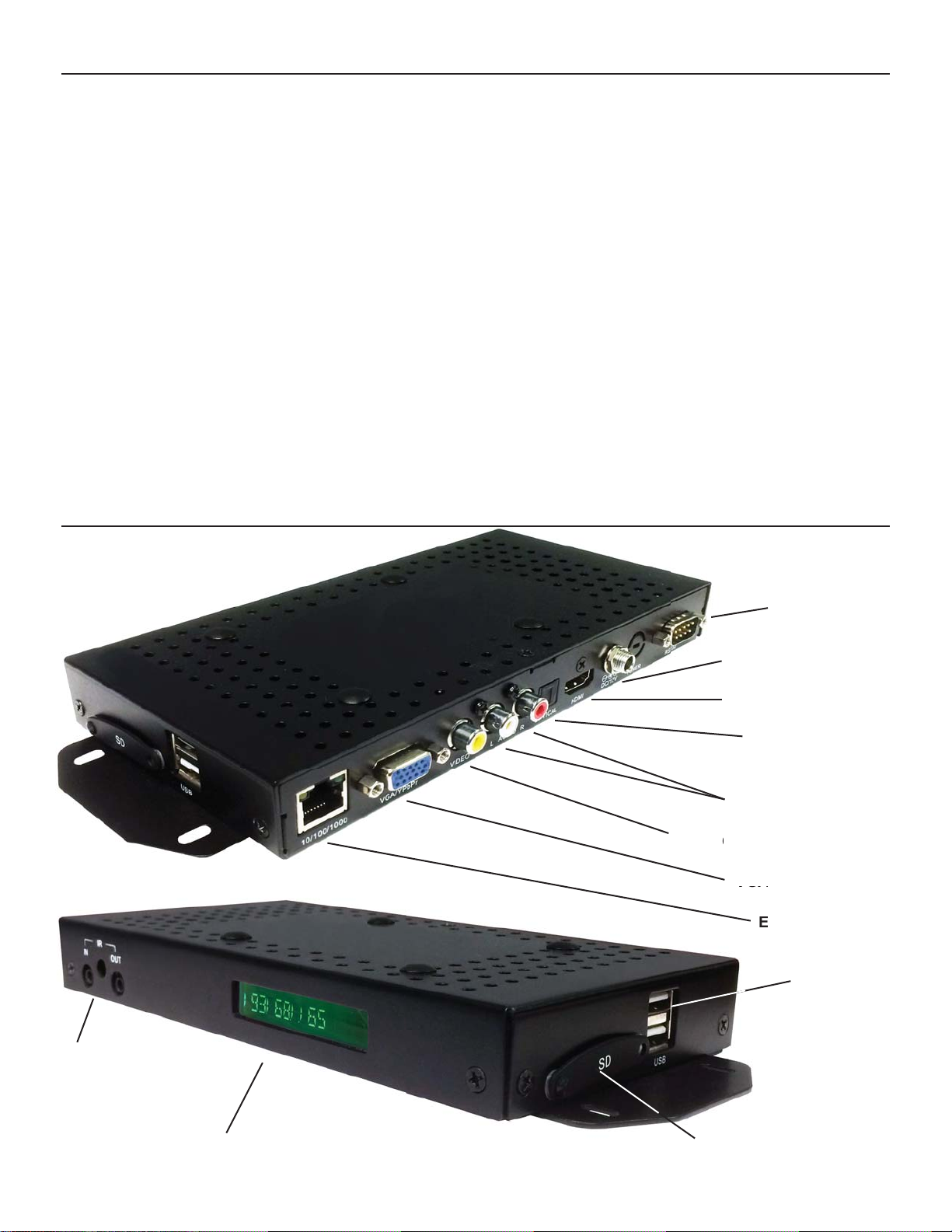
Back of DNP100
Front of DNP100
RS232 SERIAL
CONTROL PORT
12 VDC POWER PORT
HDMI VIDEO OUTPUT
OPTICAL TOSLINK
AUDIO OUTPUT
L / R AUDIO OUTPUT
COMPOSITE VIDEO OUTPUT
COMP
VGA VIDEO OUTPUT
ETHERNET PORT
USB PORTS
IR (INFRARED)
REMOTE CONTROL
INTERFACE
LCD STATUS WINDOW
(continued on Page 6)
SD MEMORY CARD SLOT

6
INTRODUCTION (continued)
The DNP100 is capable of driving a wide variety of displays at RESOLUTIONS of 480i up to 1080p
and at bit rates of up to 40 Mbps (MPEG2 fi le type).
CONNECTIONS
Connect the following CABLE TYPES mentioned in this section to the appropriate INPUT, OUTPUT,
OR COMMUNICATION PORT, according to your specifi c application’s requirements.
THE DNP100 DRAKE NETWORK PLAYER
Connect a DISPLAY CABLE, listed below, between the DNP100 and the DISPLAY (TV or
MONITOR), switch, or distribution amplifi er in your VIDEO DISTRIBUTION System:
*NOTE: The HDMI and VGA (COMPONENT) VIDEO OUTPUTS are both active simultane-
ously, provided that the VIDEO OUTPUT RESOLUTION is set to a RESOLUTION compati ble with both VIDEO OUTPUT Types.
A. HDMI CABLE (Included) Use an HDMI CABLE to connect between the HDMI VIDEO
OUTPUT on the DNP100 and the HDMI VIDEO INPUT on the display device.
*Note: If HDMI CABLES are being used, separate audio cables are not required as
long as the receiving device supports HDMI-embedded audio.
B. VGA (DB15) TO RCA CABLE Use a VGA (DB15) TO RCA CABLE when using the VGA
VIDEO OUTPUT to translate from VGA to COMPOSITE VIDEO.
C. VGA TO VGA CABLE Use this for delivering the video signal from the VGA VIDEO OUT PUT to a device that receives video through a VGA INPUT. The DNP100 is capable of out putting VGA signals at various resolutions. To make these VIDEO OUTPUT RESOLUTION
changes within the DRAKE DNP SERIES DIGITAL SIGNAGE MANAGER, click:
*NOTE: A VIDEO OUTPUT RESOLUTION of 480i is standard and available by COM-
POSITE VIDEO OUTPUT at all times.
D. RCA CABLE Use a single RCA CABLE, connected between the COMPOSITE VIDEO
OUTPUT on the DNP100 to a COMPOSITE VIDEO INPUT on the display device. Typical ly, this RCA CABLE is used in conjunction with a RCA CABLE PAIR (below) to also deliver
AUDIO.
E. RCA CABLE PAIR Use a RCA CABLE PAIR for outputting audio through the L / R AUDIO
OUTPUT. This is typically used in conjunction with the COMPOSITE VIDEO OUT.
DISPLAY CABLES
Tools Tab>Set Video Output>Custom>Resolution (from drop down)>Apply Video Output
F. TOSLINK CABLE Use a TOSLINK CABLE between the OPTICAL TOSLINK AUDIO OUT PUT on the DNP100 and a TOSLINK INPUT on the display or other audio device.
OTHER CABLES
POWER CABLE Insert the POWER CABLE plug into the 12VDC POWER PORT on the
DNP100. Turn the threaded security ring clockwise to tighten. To Power Up the DNP100, in sert the AC Plug of the power supply into an electrical outlet.
To confi gure the DNP100 to have a default start-up item begin playback once full boot-up of
the unit has completed, a successful LOAD of a PLAYLIST, LAYOUT, or BOTH to the DNP100
must be completed (see Chapter 5, LOADING PLAYLIST AND LAYOUT on Page 28).
RS-232 CABLE Use a RS-232 CABLE between the RS-232 PORT on the DNP100 and a RS 232 PORT on your PC, laptop, or other control device. The DNP100 may be controlled via
the RS-232 Serial Port with the purchase and use of the DCM ENTERPRISE MANAGEMENT
SUITE FOR WINDOWS® (see APPENDIX, Page A3 for product features).
NETWORK / CROSSOVER CABLE These two CABLES are used for communicating with
and LOADING content to the DNP100. Insert one end of the CABLE into the DNP100’s ETH ERNET PORT and the other end into the ETHERNET PORT on your PC, laptop, or other con-
trol device (which CABLE to use, see Steps 2A, 2B under GETTING STARTED, Page 7).
(continued on Page 7)

THE DNP100 DRAKE NETWORK PLAYER
7
INTRODUCTION (continued)
As well as being the owner and operator of the commercial grade hardware solution that will allow you
to embark into the world of DIGITAL SIGNAGE with fl awless custom HD video playback, you now also
own and control a powerful all-in-one signage and community channel content design and management system: the Drake DNP Series Digital Signage Manager content management and layout creation suite.
You will need to download the latest version of this software to your PC from the following URL:
http://tinyurl.com/DNPSeriesDigitalSignageManager
GETTING STARTED
The following steps will allow you to get started quickly on setting up your DNP100 for operation
(there is also an illustrated Quick Start Guide for loading content onto the DNP100 included in the
original DNP100 packaging):
1. Download Drake’s DNP Series Digital Signage Manager software from the URL listed above.
2. Connect your PC to the DNP100 in one of the following two ways:
A. THROUGH A LOCAL NETWORK
Connect an Ethernet cable to the Ethernet port on the back of the DNP100 and connect
the other end of the Ethernet cable to your Network or router.
B. DIRECTLY FROM YOUR PC TO THE DNP100
Connect a Crossover Cable to the Ethernet Port on the back of the DNP100 and con nect the other end of the Crossover Cable to the Ethernet Port on your PC.
3. Connect the included HDMI cable (or VGA Cable, or RCA Jack Cables) to your TV / Monitor for
viewing.
4. Connect the included power supply to the DNP100.
5. Plug the DNP100’s Power Supply in to a 120 VAC rated electrical wall power outlet.
*NOTE: This is how you will turn the DNP100 ON and OFF (by connecting it to / disconnect-
ing it from a power source).
The DNP100 will take approximately 2 minutes to boot up completely.
6. Once the DNP100 has completed booting up, press the MENU Button on the DNP100’s
Accessory Remote Control. Alternatively, if you do not own the DNP100’s Accessory Remote
Control, you will need to connect a USB keyboard to one of the two USB ports on the side of the
DNP100 and then press the F1 key in order to pull up the MAIN MENU.
7. Once the MAIN MENU has been accessed and is displayed, use the Arrow Keys (▲,▼) on the
Accessory Remote Control or on the USB Keyboard to navigate to the PLAYER SETUP option
and press ENTER.
*NOTE: To return to the previous MENU SCREEN, press the MENU Button on the DNP100’s
Accessory Remote Control or press the F1 key on the USB keyboard.
8. On the PLAYER SETUP MENU Screen, select the NETWORK SETTINGS option by pressing
ENTER.
9. On the NETWORK SETTINGS Screen, select the WIRED CONNECTION option (“wireless
connection” is not currently available on the DNP100) by pressing ENTER.
NETWORK SETTINGS Screen
The NETWORK SETTINGS Screen will give you all sorts of helpful technical information that
(continued on Page 8)
8
NETWORK SETTINGS Screen (continued)
may come in handy later on in the day to day use of the DNP100. All of this information can be
THE DNP100 DRAKE NETWORK PLAYER
found within the Drake DNP Series Digital Signage Manager software so you won’t be required
to repeat accessing the MENU on the DNP100 this way again unless you intend on connecting
to the DNP100 via NETWORK one day and PC-to-DNP100 DIRECTLY the next, or vice versa.
What you do need to do on this screen this initial time is make sure that the USE DHCP setting
is correct. Make sure the DHCP box has an “X” in it if you are connecting to the DNP100
through a local network. If you are connecting directly to the DNP100 with your PC with a
Crossover Cable, ensure that the USE DHCP box does not have an “X” in it.
X
□
LOCAL NETWORK CONNECTION
=
DIRECT CONNECTION / CROSSOVER CABLE
= □
10. To place an “X” in the empty box, use the Arrow Keys (▲,▼) on the Accessory Remote Control
or on the USB Keyboard to navigate to and highlight the box next to the words USE DHCP and
press ENTER. Pressing ENTER in this fi eld alternates between an “X” and no “X”.
11. Once you have the correct setting entered, use the Arrow Keys (▲,▼) to navigate to and high light the SAVE CHANGES bar at the bottom of the screen and press ENTER. Congratulations,
your DHCP setting is now saved.
12. Press the MENU Button on the DNP100’s Accessory Remote Control (or the F1 key on the USB
Keyboard) to exit the NETWORK SETTINGS Screen. Continue pressing the MENU Button on
the Remote Control (or the F1 key on the Keyboard) until all MENU screens have been exited
(including the original MAIN MENU Screen).
DRAKE DNP SERIES DIGITAL SIGNAGE MANAGER
Launch Drake’s DNP Series Digital Signage Manager software by clicking the icon on your desktop. Each time you launch Drake’s DNP Series Digital Signage Manager software (herein referred
to as “DSM”), the software will scan for any active DNP100’s that your PC is connected to directly or
through your local network.
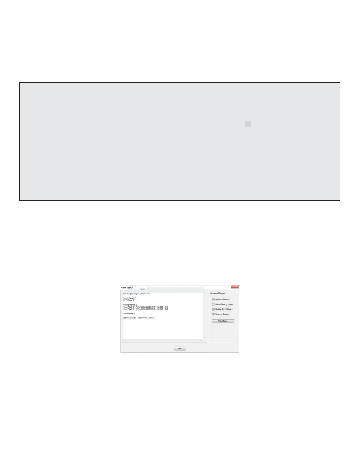
Image: DSM PLAYER SEARCH Window
From this PLAYER SEARCH pop-up window, you may select preferences that will take effect the next
time a PLAYER SEARCH is run, including: manually add a previously unknown DNP100 to your PC’s
known DNP100 inventory, have DSM automatically remove any missing/non-active DNP100’s from
the PC’s known DNP100 inventory (typically, this is unnecessary), have DSM update any changed IP
addresses of active DNP100’s in the PC’s DNP100 inventory fi les, and if you wish to change PLAY-
ER SEARCH from running automatically when DSM is launched. Click the SET DEFAULTS Button to
save any changes.
(continued on Page 9)
THE DNP100 DRAKE NETWORK PLAYER
9
DRAKE DNP SERIES DIGITAL SIGNAGE MANAGER (continued)
You may also perform a manual PLAYER SEARCH by selecting the TOOLS tab at the top left of the
main DSM Window, and then selecting PLAYER SEARCH from the list of options.
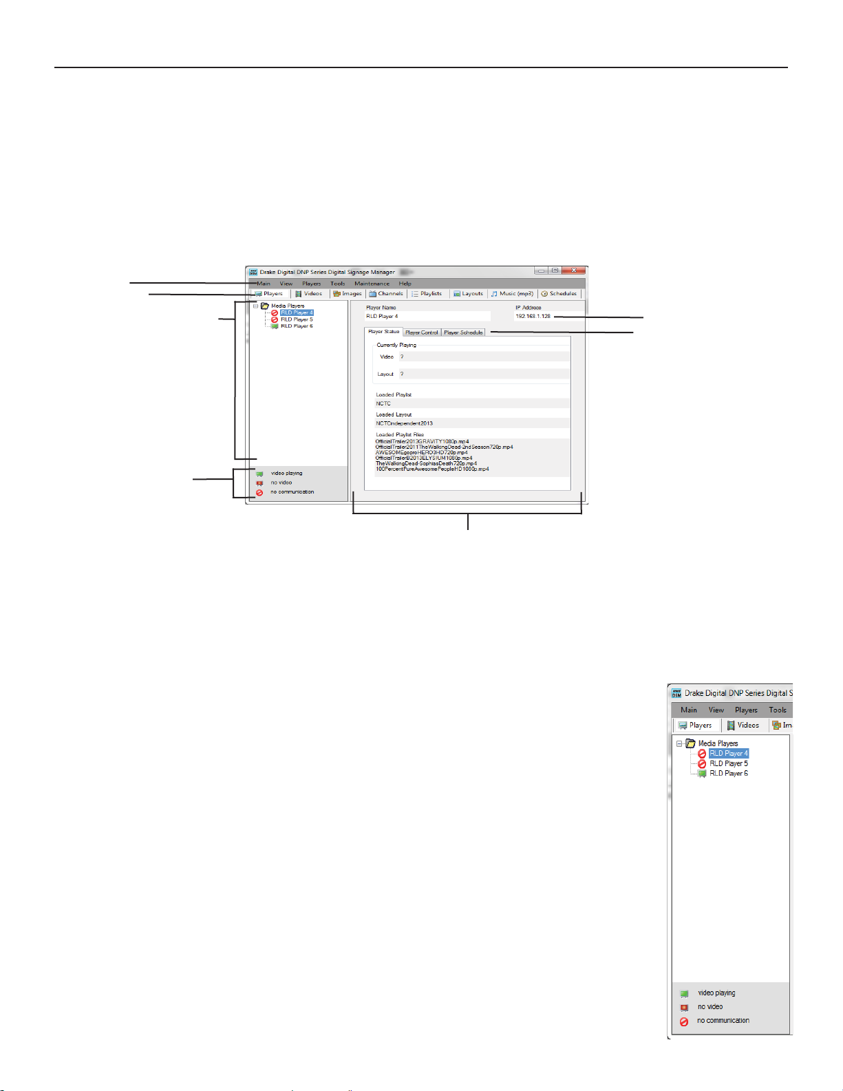
DSM MAIN Window
Welcome to the MAIN Window of the DRAKE DNP SERIES DIGITAL SIGNAGE MANAGER (referred
to herein as DSM). After DSM completes its initial search for DNP100’s on your network or Crossover
Cable, the MAIN Window should appear on your PC/laptop like this:
Windows Tabs
DSM Section Tabs
DNP100 Network Inventory List Current DNP100 IP Address
Current DNP100 Control Tabs
DNP100 Player Status Key
Current DNP100 Control / Information Monitor
Image: DSM MAIN Window, (PLAYERS Tab Selected)
The overall appearance of the MAIN Window is dictated by your selection of a SECTION TAB. The
SECTION TABS are divided into eight (8) sections/tabs: PLAYERS, VIDEOS, IMAGES, CHANNELS,
PLAYLISTS, LAYOUTS, MUSIC (Mp3s), and SCHEDULES.
PLAYERS Tab Network Inventory List
The PLAYERS Tab represents an intuitive information and control interface
for your DNP100. Once launched, the fi rst part to review of DSM’s PLAY-
ERS Tab is the DNP100 NETWORK INVENTORY LIST. This pane will list
all DNP100’s that you have ever had connected through your local network
and recognized by DSM (unless you have elected for DSM to remove “mis sing players” in the PLAYER SEARCH pop-up window). A PLAYER STAT US KEY is located at the bottom of the NETWORK INVENTORY LIST to
report if VIDEO PLAYBACK is occurring on any listed DNP100’s, or if there
is NO COMMUNICATION with any individual DNP100 listed.
To select a DNP100 to control or ADD content, click on the name of the de sired DNP100. The DNP100’s name will then be highlighted, and the
CONTROL / INFORMATION MONITOR pane will be populated with that
DNP100’s information, as well as allowing you to make direct changes to
that DNP100’s content, scheduling, playlists, layouts, slide shows, Video
Output Resolution, name, description, and even its IP address.
(continued on Page 10)
10
PLAYERS Tab - Control / Information Monitor (continued)
The PLAYERS Tab’s Control / Information Monitor pane both displays information about your
currently selected DNP100 and also allows you to commit settings and functions to the
DNP100, depending on the selection of one of three tabs within the Control / Information Moni tor Pane: PLAYER STATUS, PLAYER CONTROL, and PLAYER SCHEDULE.
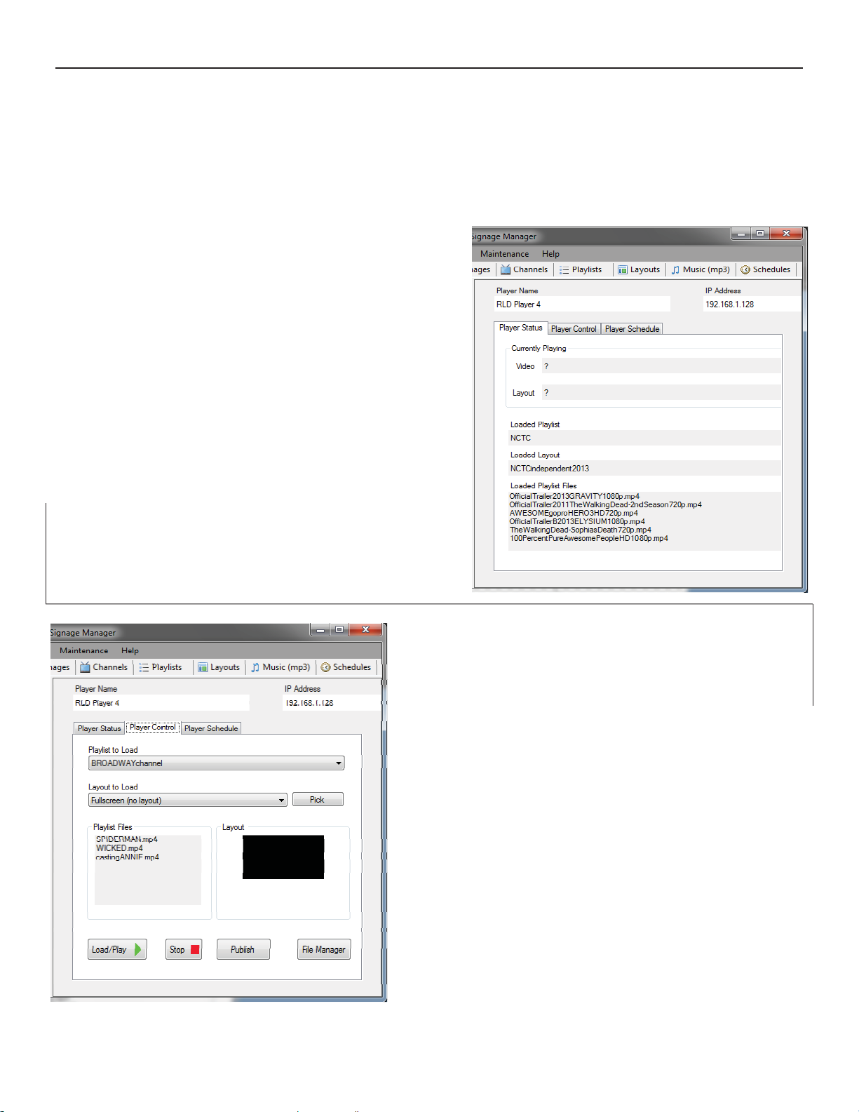
PLAYER STATUS TAB
PLAYER STATUS gives the real time
STATUS of your selected DNP100 regard ing the following variable parameters:
Currently Playing Video
Currently Playing Layout
Loaded Playlist
Loaded Layout
Loaded Playlist Files
The name of the player and its IP address are
visible at the top of the CONTROL / INFORMA TION MONITOR pane regardless of the inner pane tab selected, to ensure you are always
sending commands to the correct DNP100.
THE DNP100 DRAKE NETWORK PLAYER
PLAYER CONTROL TAB
PLAYER CONTROL is where you will actually push
new content fi les, PLAYLISTS, LAYOUTS, and SET-
TINGS to the DNP100 from DSM. Two dropdown lists
allow you to choose your PLAYLIST and LAYOUT:
PLAYLIST TO LOAD
LAYOUT TO LOAD
To LOAD the DNP100 for immediate playback:
1. Select PLAYLIST from PLAYLIST TO LOAD
2. Select LAYOUT from LAYOUT TO LOAD
3. Click the LOAD / PLAY Button
A window will open to show the progress of the
LOAD, ending with “Load/Play successful” if loaded
properly. To stop playback, click the STOP Button.
(More information on the LOAD / PLAY Button, as well
as other methods to LOAD PLAYLIST, LAYOUT, or
SCHEDULE to the DNP100 are located in Chapter 5,
Loading Playlist and Layout.)
(continued on Page 11)
THE DNP100 DRAKE NETWORK PLAYER
PLAYER CONTROL TAB (continued)
On the PLAYER CONTROL TAB, you will notice three other buttons:
PICK (next to the LAYOUT TO LOAD dropdown list)
PUBLISH
FILE MANAGER
The PICK Button was created for the purpose of confi rming the LAYOUT that has been
selected in the LAYOUT TO LOAD dropdown list. It was designed as a means to make
the operator of the DNP100 confi rm or “double-check” that the selected LAYOUT show-
ing in the dropdown window is defi nitely the LAYOUT that the operator wishes to LOAD
to the DNP100 for immediate playback. However, you are not required to click the PICK
Button in order to LOAD your desired LAYOUT to the DNP100.
The PUBLISH Button is for saving to a folder the currently selected PLAYLIST and LAY OUT (as well as any operator-added content that make up or are contained within the
PLAYLIST or LAYOUT). The PUBLISH Button is one of three ways to LOAD content to
the DNP100 as well as for saving copies of your PLAYLIST and LAYOUT for backup.
11
(Information on using the PUBLISH Button to LOAD PLAYLIST and LAYOUT to a USB
Drive or SD Card, please see Chapter 5, Loading Playlist and Layout.)
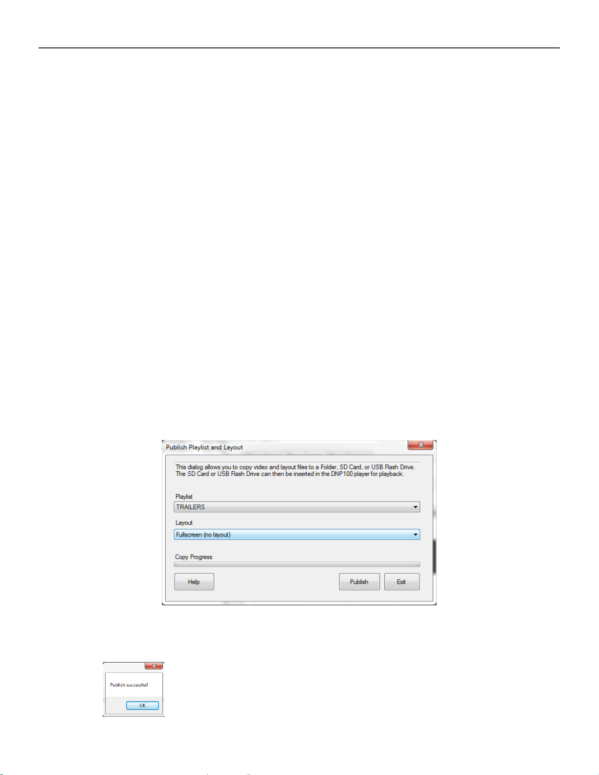
PUBLISH TO A FOLDER
To save your selected PLAYLIST and LAYOUT to a folder for backup, click the
PUBLISH Button. The following window will launch in front of the DSM MAIN
Window:
Clicking the PUBLISH Button will open another new window for you to select a
location / folder in which to save the PLAYLIST, LAYOUT, and any content asso ciated with them.
A progress bar is located at the bottom of this window to indicate when the
PUBLISH Save has successfully completed. Do not close the window
shown above until the progress bar is completely fi lled and a small “Pub-
lish Successful” notifi cation window has opened.
(continued on Page 12)
12
PLAYER CONTROL TAB (continued)
The FILE MANAGER Button allows you to quickly access a list of the entire inventory of
all fi les (VIDEO, IMAGE / LAYOUT) that are currently stored on the DNP100’s SD Mem-
ory Card.
MANAGE YOUR FILES
Click the FILE MANAGER Button to open a new window where you can:
PLAY SELECTED fi le (or PLAY ALL) directly
DELETE SELECTED fi le (or DELETE ALL) from the SD Card
COPY SELECTED fi le from the DNP100’s SD Card to your PC / laptop
REFRESH LIST to ensure that any changes have taken effect
The FILE MANAGER Window will also give you storage information regarding how
much space all of your fi les are taking up on the SD Card, as well as how much free
space remains available on the SD Card.
THE DNP100 DRAKE NETWORK PLAYER
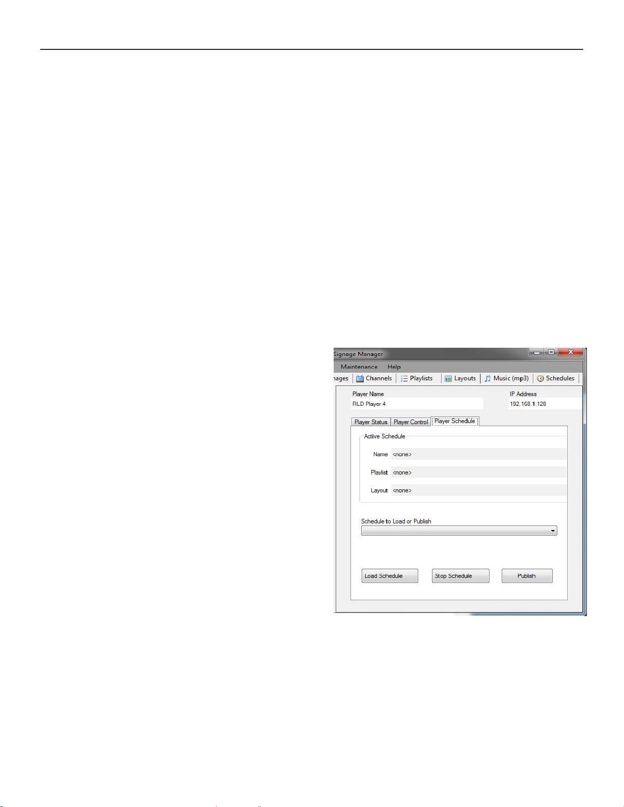
PLAYER SCHEDULE TAB
PLAYER SCHEDULE is much like the
CONTROL TAB, but is specifi c to PLAY-
LIST and LAYOUT SCHEDULING. It
will allow you to select a predefi ned
custom SCHEDULE of your own mak ing from a dropdown list. The SCHED ULE will already have predetermined
start and end times, as well as prede termined PLAYLIST and LAYOUT alrea dy selected. Simply select your named
SCHEDULE and click the LOAD
SCHEDULE Button to LOAD the
SCHEDULE to the DNP100. Likewise,
you may STOP any currently LOADED
SCHEDULE by clicking the
STOP SCHEDULE Button.
The PUBLISH Button works just like
the PUBLISH Button on the CONTROL TAB, requiring you to select a destination folder
(or SD Card or USB Drive) in which to save the selected SCHEDULE.
(More information on using the PUBLISH Button to LOAD a PLAYLIST and LAYOUT, or
to LOAD A SCHEDULE to a USB Drive or SD Card can be found in Chapter 5, Loading
Playlist and Layout.)

THE DNP100 DRAKE NETWORK PLAYER
13
ADDING CONTENT
ADDING content to DSM is a fast and easy procedure that will be familiar to most operators of the
DNP100. There are a few key points to keep in mind in order to ensure a smooth experience when
uploading content to the DNP100:
1. Uploading Content Files to your DNP100 is a 2 Step Process.
First, you must
ADD your content fi les to DSM.
Second, you must then push that content to the DNP100 by using the LOAD / PLAY Button
or the PUBLISH Button, both of which are located on the PLAYERS Tab - PLAYER
CONTROL TAB. (See Chapter 5, Loading Playlist and Layout for more detail))
2. File Names Can Not Have Spaces (“ ”) or Punctuation Marks in Them.
The DNP100 uses a Linux-based operating system. A Linux system operates differently
than how a Windows-based OS operates. One notable difference: fi le names with spaces
or punctuation marks will cause a LOAD ERROR. Typically, DSM will notify you with a
warning prompt when this occurs as you are ADDING a fi le, however, to ensure fl uid oper-
ation when ADDING fi les, rename any fi les before ADDING to DSM to avoid this situation.
3. Be sure that the type of fi le that you are ADDING is recognized and supported.
MEDIA TYPE FILE TYPE SUPPORTED
Video MPEG2
MPEG4.2
MPEG4.10 (H.264)
WMV9
VC-1
Image / Graphic JPEG
GIF
PNG
(Image / Graphic Recommended Resolution:
1920x1080 for Full Screen layout)
Audio MPEG1 (Layers I, II, and III; MP3 - 2.0)
MPEG4 (AAC-LC 5.1 / HE-AAC 5.1)
WMA9 2.0
Dolby Digital 5.1
FLAC
MP3 (Optional, Requires License)
Microsoft Power Point Must be converted to video or JPEG Slides
3. Be certain there is enough free space on the DNP100’s removable SD Memory Card.
The DNP100 comes standard with a 8 GB SD Memory Storage Card that is removable and
thus replaceable with a properly formatted greater-capacity SD Memory Storage Card. The
SD Card acts as the primary content / fi le storage for the DNP100.
(Successful testing on SD Memory Cards of up to 32 GB storage capacity have been com-
pleted. No testing beyond 32 GB has been completed.)
(continued on Page 14)
14
THE DNP100 DRAKE NETWORK PLAYER
ADDING CONTENT (continued)
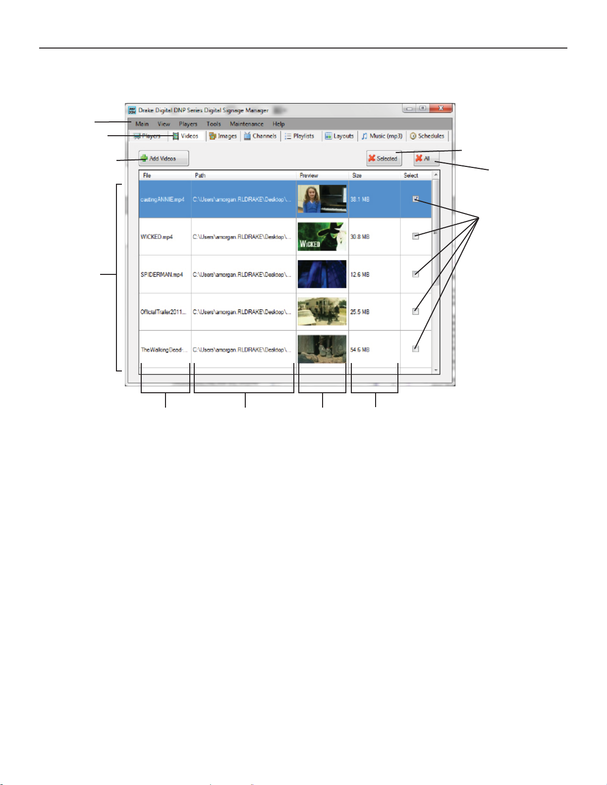
VIDEOS Tab
Windows Tabs
DSM Section Tabs
ADD VIDEOS Button
VIDEO FILE List
DELETE SELECTED Button
DELETE ALL Button
SELECT CHECK Boxes
File Name Path to File Preview File Size
The VIDEOS Tab (located to the right of the PLAYERS Tab) is where you will ADD your VIDEO
content. The procedure for ADDING VIDEO will be extremely familiar to those with any experi ence opening fi les from within a folder on a PC (Windows OS).
ADD A VIDEO FILE:
1. Click the ADD VIDEOS Button. A window will open for you to locate your desired VIDEO
fi les on your PC / laptop.
2. Single-click on the VIDEO fi le/s that you wish to ADD (you may ADD multiple VIDEO
fi les at the same time by holding down the “Ctrl” key on your keyboard, and then single-
clicking each VIDEO fi le that you wish to ADD).
3. Click the OPEN Button on the pop up window. The VIDEO fi le/s will commence being
ADDED to the VIDEO FILE List on the VIDEOS Tab in DSM.
Once the VIDEO fi le has been ADDED to DSM, the VIDEO fi le will auto-populate as the low-
est entry in the VIDEO FILE List.
At some point after using the DNP100 and DSM many times, you may wish to reduce clutter in
the VIDEO FILE List by removing any VIDEO fi les that you are certain you will no longer need
for your current DNP100 nor for any other additional DNP100’s in the future.
(continued on Page 14)
 Loading...