

Page 1
DDC864A DIGITAL DOWNCONVERTER 1
TM
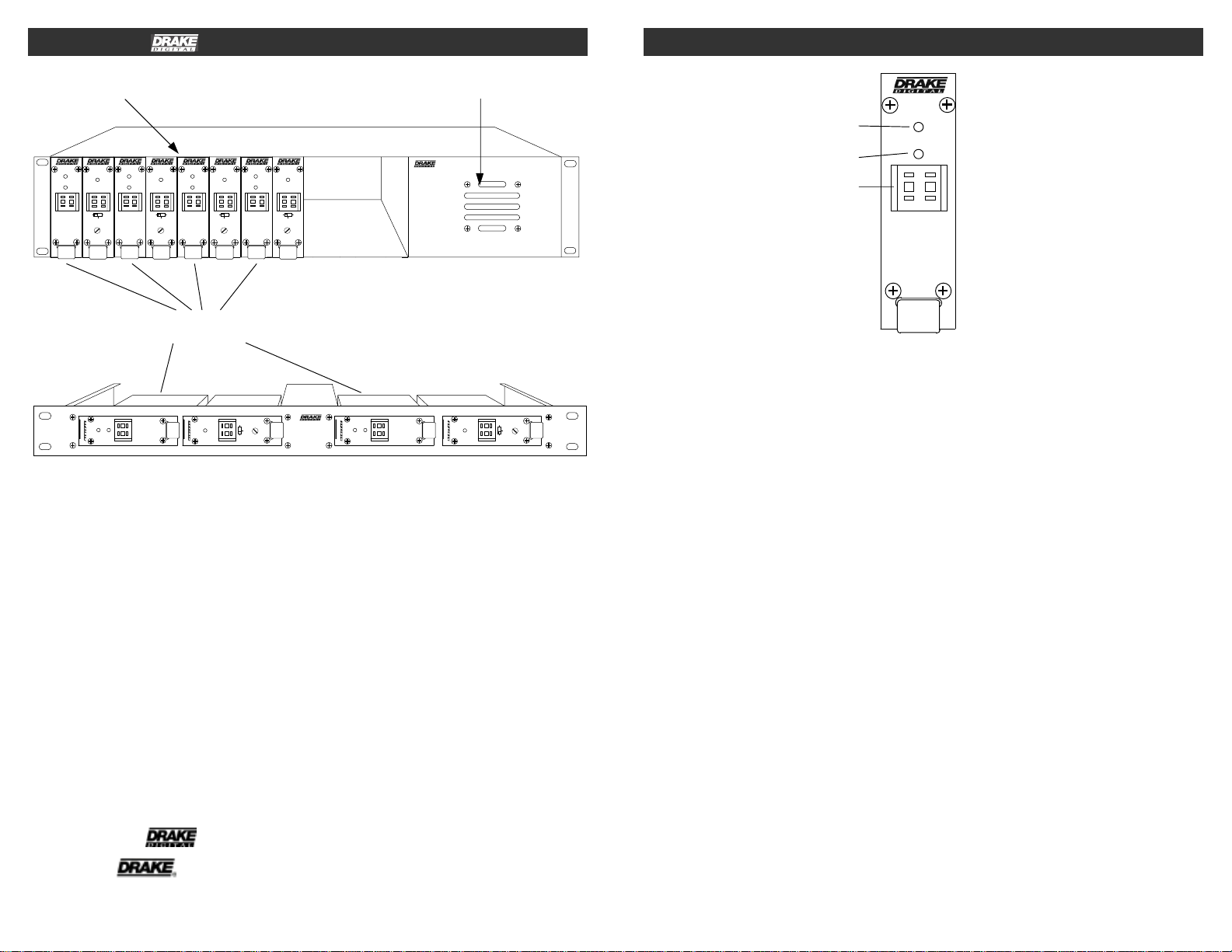
2 FRONT PANEL CONTROLS and INDICATORS
12 POSITION RACK MOUNT POWER SUPPLY
DUC864
DDC864A
25
PWR/
PWR/
ERROR
ERROR
SIGNAL
21
CATV
BC
TV
+100
CATV
GAIN
DDC864A
25
DUC864
PWR/
PWR/
ERROR
ERROR
SIGNAL
21
CATV
BC
TV
+100
CATV
GAIN
DDC864A
25
DUC864
PWR/
PWR/
ERROR
ERROR
SIGNAL
21
CATV
BC
TV
+100
CATV
GAIN
DDC864A
25
DUC864
PWR/
PWR/
ERROR
ERROR
SIGNAL
21
CATV
BC
TV
+100
CATV
GAIN
PS8
DDC864A
DOWNCONVERTER
TV
BC
DDC864A
SIGNAL
PWR/
ERROR
25
DUC864
PWR/
GAIN
ERROR
CATV
35
+100
CATV
The R.L. Drake DDC864A is a low noise
downconverter designed for translating
digital ATSC, 8VSB signals from their off-air
channel to a 44 MHz IF output. The output of
the DDC864A can be connected to a DUC
series upconverter to place the digital signal
on a new output channel.
SIGNAL
PWR/
ERROR
25
DDC864A
DRMM4
The DDC864A provides low noise figure and low
phase noise as well as a flat passband to
minimize signal deterioration.
The DDC864A is optimized for use with ATSC
8VSB modulation in a 6 MHz wide channel
assignment. The passband is designed for
DUC864
BC
PWR/
ERROR
28
CATV
optimized operation with 8VSB signals in an
When the DDC864A is used with the
DUC864, "on channel" conversions, (the
same input channel on the DCC and output
adjacent channel environment. For translation of
QAM signals, the Drake model DQT1000 is
preferred for this task.
channel on the DUC) are acceptable.
DDC864A
PWR/
ERROR
SIGNAL
25
POWER SUPPLY
F1
F2
F3
Figure 1
F1 - POWER/ERROR Indicator
Lights when the unit is connected to the
TV
GAIN
CATV
+100
required source of DC power via the rear panel
DC INPUT connector. A flashing condition
indicates an invalid channel setting or other
conditions that would cause the unit to operate
F2 - SIGNAL Indicator
Lights when a signal is present.
F3 - Channel Number Switch
Sets the desired operating channel for standard
Broadcast TV channels 02 through 69.
on an invalid channel. The RF output is
switched off for flashing (ERROR) conditions.
TM is a trademark of the R.L. Drake Holdings, LLC
is a registered trademark of the R.L. Drake Holdings, LLC
Copyright 2008 R.L. Drake Holdings, LLC P/N: 3852391B-9-2008
.
Page 2
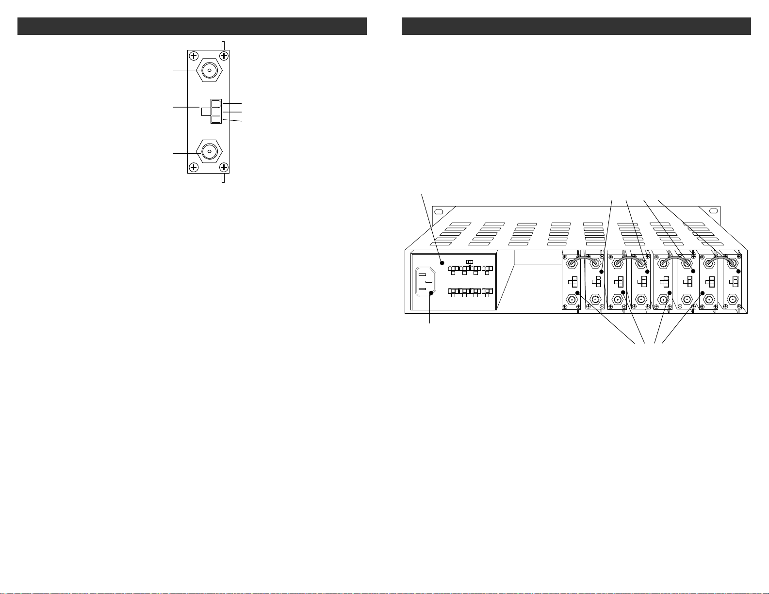
REAR PANEL CONNECTIONS 3
4 INSTALLATION
R1
R2
R3
R1 - IF OUTPUT Connector
This is the 44 MHz IF output. The level is
+30 dBmV.
R2 - DC INPUT Connector
This 3-pin connector (Male) accepts the
appropriate mating DC power cable. Observe
proper orientation and wiring.
R3 - RF IN Connector
This is the downconverter RF input from an
antenna or CATV feed.
+12 V
GND
+5 V
Figure 2
IF OUT
POWER
RF IN
+12 V
GND
+5 V
CONNECTIONS AND CONTROLS
All connections to and from each upconverter
are made through the rear panel.
DESCRIPTION
Figure 3 shows a typical installation utilizing the
Drake DRMM12 rack with 4 DDC864A
downconverters, and 4 DUC upconverters.
A PS8 power supply module is used to power all
units.
POWER
SUPPLY
DC OUTPUTS X 8
12V GND 5V
DC OUTPUT RATING.
TOTAL OF ALL OUTPUTS: +5V:6A MAX.
+12V:2.5A MAX.
100-240 V ~
50/60 Hz
85 WATTS
AC POWER
CONNECTOR
RACK MOUNTING
Adequate ventilation is very important in
multichannel installations. Units should be
spaced apart vertically by at least 1.75"
wherever possible, and some air movement is
mandatory in enclosed rack cabinets.
Excessive heat will shorten component life and
performance will be degraded without
proper cooling.
DDC864A
DIGITAL
DOWNCONVERTERS
IF OUT
IF IN
POWER
POWER
+12 V
+12 V
GND
GND
+5 V
RF OUT
GND
+5 V
RF IN
IF OUT
IF IN
POWER
POWER
+12 V
+12 V
GND
+5 V
+5 V
RF IN
RF OUT
IF OUT
IF IN
POWER
POWER
+12 V
+12 V
GND
GND
+5 V
+5 V
RF IN
RF OUT
DUC864
UPCONVERTERS
Figure 3
IF OUT
IF IN
POWER
POWER
+12 V
+12 V
GND
GND
+5 V
+5 V
RF IN
RF OUT
Page 3
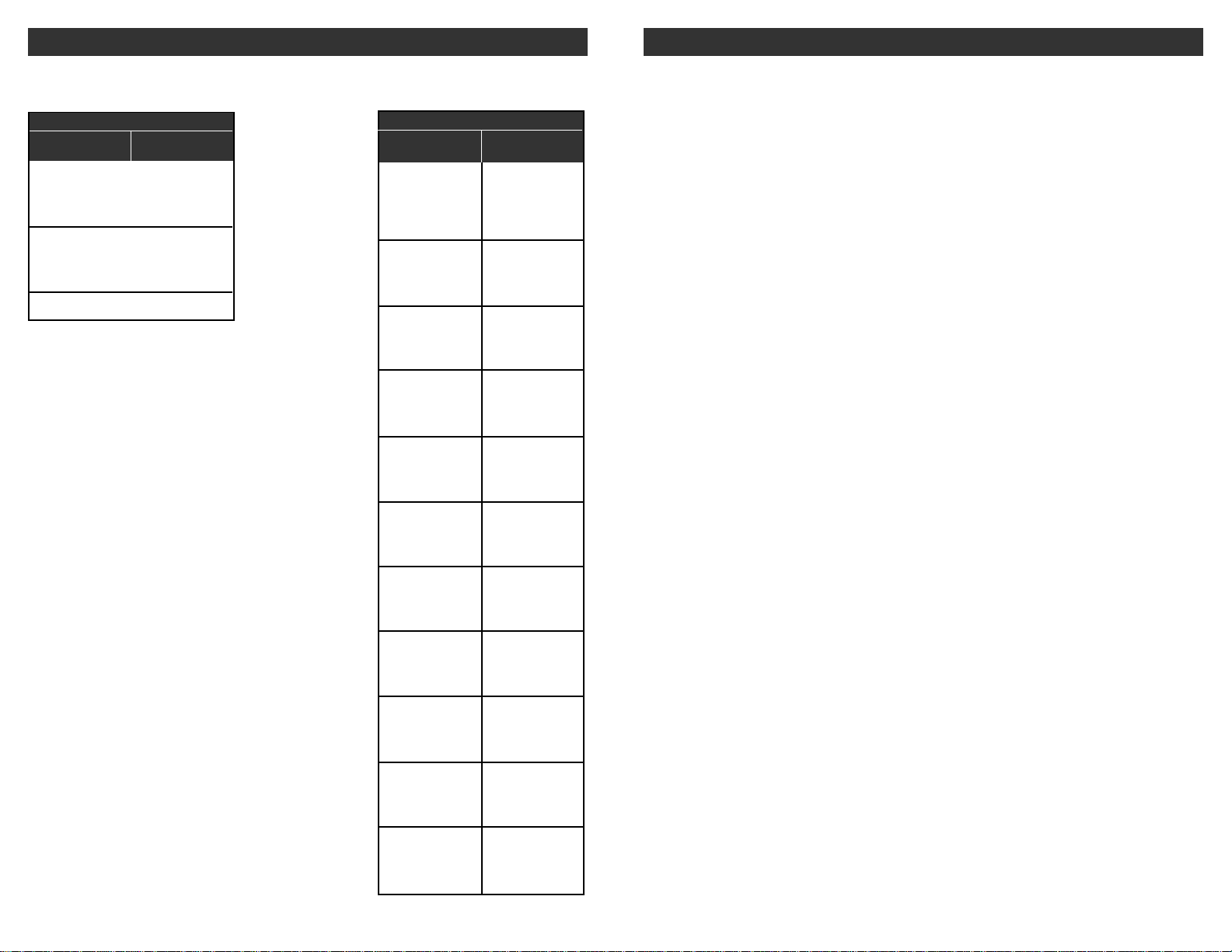
TABLE 2:
BC TV
BROADCAST TV CHANNEL INPUT FREQUENCIES 5
CATV CHANNEL INPUT FREQUENCIES 5
6 SPECIFICATIONS
VHF BROADCAST CHANNELS
Channel
Number
2
3
4
5
6
7
8
9
10
11
12
13
Center of Channel
Frequency (MHz)
57
63
69
79
85
177
183
189
195
201
207
213
UHF BROADCAST CHANNELS
Channel
Number
14
15
16
17
18
19
20
21
22
23
24
25
26
27
28
29
30
31
32
33
34
35
36
37
38
39
40
41
42
43
44
45
46
47
48
49
50
51
52
53
54
55
56
57
58
59
60
61
62
63
64
65
66
67
68
69
Center of Channel
Frequency (MHz)
473
479
485
491
497
503
509
515
521
527
533
539
545
551
557
563
569
575
581
587
593
599
605
611
617
623
629
635
641
647
653
659
665
671
677
683
689
695
701
707
713
719
725
731
737
743
749
755
761
767
773
779
785
791
797
803
RF INPUT
Frequency Range:
Input level Range:
Impedance:
Noise Figure:
Image Rejection:
Output
IF Frequency:
Level:
Impedance:
Frequency Stability:
Channel Bandwidth:
SSB Phase Noise:
Amplitude Flatness
(6 MHz Channel):
GENERAL
DC Power Input:
Operating Temperature:
Size:
Weight:
54 to 806 MHz;
OFF-AIR channels 2 to 69,
-25 dBmV to +30 dBmV.
75 Ohms, return loss of 8 dB
10 dB, maximum
>75 dB.
44 MHz.
+30 dBmV, ±1 dB.
75 Ohms, return loss of 20 dB
±30 PPM.
6 MHz SAW filtered.
-88 dBc @ 10 kHz offset.
±1 dB over 4 MHz
+12 V ±5% @ 150 mA .
+5 V ±5% @ 150 mA.
00 C to +500 C ambient.
1” W x 3.5” H x 9.25” D. (2.5 cm) W x (8.9 cm) H x (23.5 cm) D.
11 oz. (0.31 Kg).
Specifications subject to change without notice or obligation.
Page 4

WARRANTY 7
THREE YEAR LIMITED WARRANTY
R.L. DRAKE COMPANY warrants to the original purchaser this product shall be free from defects in material or workmanship for three (3)
years from the date of original purchase.
During the warranty period the R.L. DRAKE COMPANY or an authorized Drake service facility will provide, free of charge, both parts and
labor necessary to correct defects in material and workmanship. At its option, R.L. DRAKE COMPANY may replace a defective unit.
To obtain such warranty service, the original purchaser must:
(1) Retain invoice or original proof of purchase to establish the start of the warranty period.
(2) Notify the R.L. DRAKE COMPANY or the nearest authorized service facility, as soon as possible after discovery of a possible defect,
of:
(a) the model and serial number,
(b) the identity of the seller and the approximate date of purchase; and
(c) A detailed description of the problem, including details on the electrical connection to associated equipment and the list of such
equipment.
(3) Deliver the product to the R.L. DRAKE COMPANY or the nearest authorized service facility, or ship the same in its original container
or equivalent, fully insured and shipping charges prepaid.
Correct maintenance, repair, and use are necessary to obtain proper performance from this product. Therefore carefully read the Instruction
Manual. This warranty does not apply to any defect that R.L. DRAKE COMPANY determines is due to:
(1) Improper maintenance or repair, including the installation of parts or accessories that do not conform to the quality and specifications
of the original parts.
(2) Misuse, abuse, neglect or improper installation.
(3) Accidental or intentional damage.
All implied warranties, if any, including warranties of merchantability and fitness for a particular purpose, terminate three (3) years from the
date of the original purchase.
The foregoing constitutes R.L. DRAKE COMPANY’S entire obligation with respect to this product, and the original purchaser shall have
no other remedy and no claim for incidental or consequential damages, losses or expenses. Some states do not allow limitations on how
long an implied warranty lasts or do not allow the exclusions or limitation of incidental or consequential damages, so the above limitation
and exclusion may not apply to you.
This warranty gives you specific legal rights and you may also have other rights which vary from state to state. This warranty shall be
construed under the laws of Ohio.
R.L. DRAK(+2/',1*6 LLC
710 Pleasant Valley Drive
Springboro, OHIO 45066 U.S.A.
CUSTOMER SERVICE AND PARTS TELEPHONE: +1 (937) 746-6990
TELEFAX: +1 (937) 806-1510
WORLD WIDE WEB SITE: http://www.rldrake.com
 Loading...