

Page 1

4
WARRANTY
DDA5542R Distribution Amplifier Instructions 1
ONE YEAR LIMITED WARRANTYONE YEAR LIMITED WARRANTY
ONE YEAR LIMITED WARRANTY
ONE YEAR LIMITED WARRANTYONE YEAR LIMITED WARRANTY
R.L.DRAKE COMPANY warrants to the original purchaser this product shall be free from defects in material or workmanship for one
(1) year from the date of original purchase.
During the warranty period the R.L.DRAKE COMPANY or an authorized Drake service facility will provide, free of charge, both parts
and labor necessary to correct defects in material and workmanship. At its option, R. L. DRAKE COMPANY may replace a defective
unit.
To obtain such warranty service, the original purchaser must:
(1)(1)
(1) Retain invoice or original proof of purchase to establish the start of the warranty period.
(1)(1)
(2)(2)
(2) Notify the R.L.DRAKE COMPANY or the nearest authorized service facility, as soon as possible after discovery of a possible
(2)(2)
defect, of:
(a) the model and serial number,
(b) the identity of the seller and the approximate date of purchase; and
(c) A detailed description of the problem, including details on the electrical connection to associated equipment and the list of such
equipment.
(3)(3)
(3) Deliver the product to the R.L.DRAKE COMPANY or the nearest authorized service facility, or ship the same in its original container
(3)(3)
or equivalent, fully insured and shipping charges prepaid.
Correct maintenance, repair, and use are necessary to obtain proper performance from this product. Therefore carefully read the
Instruction Manual. This warranty does not apply to any defect that R.L.DRAKE COMPANY determines is due to:
(1)(1)
(1) Improper maintenance or repair, including the installation of parts or accessories that do not conform to the quality and
(1)(1)
specifications of the original parts.
(2)(2)
(2) Misuse, abuse, neglect or improper installation.
(2)(2)
(3)(3)
(3) Accidental or intentional damage.
(3)(3)
All implied warranties, if any, including warranties of merchantability and fitness for a particular purpose, terminate one (1) year
from the date of the original purchase.
The foregoing constitutes R.L.DRAKE COMPANY’S entire obligation with respect to this product, and the original purchaser shall
have no other remedy and no claim for incidental or consequential damages, losses or expenses. Some states do not allow limitations
on how long an implied warranty lasts or do not allow the exclusions or limitation of incidental or consequential damages, so the above
limitation and exclusion may not apply to you.
This warranty gives you specific legal rights and you may also have other rights which vary from state to state. This warranty shall
be construed under the laws of Ohio.
For service information contact:
Service Department
R.L. DRAKE HOLDINGS, LLC
710 Valley Drive
Springboro Ohio, 45066 U.S.A.
Customer Service Center Phone: +1 (937) 746-6990 TELEFAX: +1 (937) 806-1510
CHANNEL LOADING CHART
CH. LOADING MAX. OUTPUT EACH CH.
77 44 dBmV
60 46 dBmV
36 48 dBmV
16 51 dBmV
12 52 dBmV
6 55 dBmV
1 60 dBmV
®
R.L. DRAKE HOLDINGS, LLC
710 Pleasant Valley Drive
WORLD WIDE WEB SITE: http://www.rldrake.com
Springboro, OHIO 45066 U.S.A.
The DRACOM model DDA5542R is a broadband
distribution amplifier designed for indoor use in both
residential and commercial buildings where RF signal
distribution in the frequency range of 54 to 550 MHz
is required. A passive return path is also provided
with a frequency range of 5 to 36 MHz. The
DDA5542R has a gain of 42 dB. The amplifier
incorporates a push-pull hybrid output amplifier to
provide a high quality, low distortion signal for a cable
TV “drop”, or, the output of an SMATV headend.
MOUNT THIS END UP
Gain is variable within a specified range using the
Gain control. A Slope control is provided to slope
the frequency response. An output test connector is
provided for convenient monitoring of the signal path.
The amplifier circuitry is designed for maximum
stability and is housed in a rugged aluminum
housing. The unit operates from 24 VDC provided by
the supplied power supply. To facilitate installation, a
connector is provided in the cable between the
amplifier and supply.
POWER LED
POWER
AC ADAPTER
TO OUTPUT
MONITOR
75 Ohm
OUTPUT
c
-30 dB OUTPUT
POWER IN
MONITOR
24 VDC
H
P
F
MODEL DDA5542R
INDOOR
DISTRIBUTION
FWD
AMP
AMPLIFIER
FORWARD PATH INTERSTAGE
SLOPE
MAX
FLAT
SUPPLY CORD
L
P
F
75 Ohm
INPUT
TO INPUT
MONITOR
Installation:
1) Unpack the Distribution amplifier and power
supply.
GAIN
MIN
MAX
FWD
AMP
LPF
HPF
-30 dB
INPUT
MONITOR
INPUT
AC MAINS CORD
Be careful not to break the controls or force the
screwdriver past the controls, as circuit damage
could result. These types of adjustments will
generally require monitoring of the signal path at the
2) Locate the Distribution amplifier to permit both the
required signal cable connections and power
connections. Note that the amplifier housing has
holes to permit mounting the amplifier to a wall using
screws, if desired. When mounting the amp on a
wall, position the amp so that the heatsink fins are on
the left and right sides and NOT on the top and
bottom. Unplug the power cord connector to facilitate
routing the cord.
test connector. The levels measured at the input
monitor connector are 30 dB lower than the input.
The levels measured at the output monitor connector
are 30 dB lower than the output. The output load
must be connected to the output connector before
measurement from the monitor output is accurate.
Gain settings must take into account the maximum
permissible output level of this amplifier unit for the
total number of input channels. Refer to the
CHANNEL LOADING CHART on page 4, for specific
3) With all cable connections made to the amplifier,
and the power supply cord routed, reconnect the DC
power cord and then plug the AC line cord into a
source of 120VAC, 50/60 Hz power.
information. The gain adjustment range is limited and
will not correct for unequal signal levels between
channels in the same band. Establishing relatively
equal signal levels between channels is essential.
The Slope control permits sloping the overall
4) Use a screwdriver to adjust the Gain and/or Slope
controls for the desired frequency response.
frequency response to compensate for the effect of
increasing signal loss of the higher frequency signals
in a length of connected coaxial cable.
TM is a trademark of the R.L. Drake Holdings, LLC
© Copyright 2013 R.L. Drake Holdings, LLC P/N: 3852724B-9-2004 Printed in Taiwan
Page 2
2
CAUTION STATEMENTS
WARNING: TO PREVENT FIRE OR
ELECTRICAL SHOCK DO NOT EXPOSE
THIS PRODUCT'S AC ADAPTER OR AMPLIFIER
TO RAIN OR MOISTURE.
¡WARNING!
RISK OF ELECTRIC SHOCK
DO NOT OPEN
TO REDUCE THE RISK OF ELECTRIC SHOCK, DO NOT
REMOVE COVER OF AC ADAPTER OR AMPLIFIER.
NO USER-SERVICABLE PARTS INSIDE.
REFER SERVICING TO QUALIFIED PERSONNEL.
An appliance and cart combination should be moved with
care. Quick stops, excessive force and uneven surfaces may
cause the appliance and cart combination to overturn.
The lightning flash with arrow head symbol, within an equilateral triangle, is intended to alert the user to the presence
of uninsulated "dangerous voltage" within the product's
enclosure that may be of sufficient magnitude to constitute
a risk of electric shock to persons.
The exclamation point within an equilateral triangle is intended to alert the user to the presence of important operating and maintenance (servicing) instructions in the literature
accompanying the appliance.
TO REDUCE THE RISK OF FIRE OR ELECTRIC SHOCK,
WARNING:
DO NOT EXPOSE THIS PRODUCT'S AC ADAPTER OR
AMPLIFIER TO RAIN OR MOISTURE. DO NOT OPEN
THE CABINET, REFER SERVICING TO QUALIFIED
PERSONNEL ONLY.
CAUTION:
TO PREVENT ELECTRIC SHOCK, DO NOT USE THE AC
ADAPTER WITH AN EXTENSION CORD RECEPTACLE
OR OTHER OUTLET UNLESS THE BLADES OF THE AC
ADAPTER CAN BE FULLY INSERTED TO PREVENT
BLADE EXPOSURE.
ATTENTION:
POUR PREVENIR LES CHOCS ELECTRIQUES, NE
PAS UTILISER CETTE FICHE POLARISEE AVEC UN
PROLONGATEUR, UNE PRISE DE COURANT OU UNE
AUTRE SORTIE DE COURANT, SAUF SI LES LAMES
PEUVENT ETRE INSEREES A FOND SANS EN LAISSER AUCUNE PARTIE A DECOUVERT.
CAUTION:
IMPORTANT SAFETY INSTRUCTIONS
1. Read Instructions—All the safety and operating instructions should be read
before the product is operated.
2. Retain Instructions—The safety and operating instructions should be retained
for future reference.
3. Heed Warnings—All warnings on the product and in the operating instructions
should be adhered to.
4. Follow Instructions—All operating and use instructions should be followed.
5. Cleaning—Unplug this product from the wall outlet before cleaning. Do not use
liquid cleaners or aerosol cleansers. Use a damp cloth for cleaning.
6. Attachments—Do not use attachments that are not recommended by the
product manufacturer as they may cause hazards.
7. Water and Moisture—Do not use this product near water—for example, near
a bathtub, wash bowl, kitchen sink or laundry tub; in a wet basement; or near a
swimming pool; and the like.
8. Accessories—Do not place this product on an unstable cart, stand, tripod,
bracket, or table. The product may fall, causing serious injury to a child or adult,
and serious damage to the product. Use only with a cart, stand, tripod, bracket, or
table recommended by the manufacturer, or sold with the product. Any mounting
of the product should follow the manufacturer's instructions, and should use a
mounting accessory recommended by the manufacturer.
9. A product and cart combination should be moved with care. Quick stops,
excessive force, and uneven surfaces may cause the product and cart combination
to overturn.
10. Ventilation—Slots and openings in the cabinet are provided for ventilation and
to ensure reliable operation of the product and to protect it from overheating, and
these openings must not be blocked or covered. The openings should never be
blocked by placing the product on a bed, sofa, rug, or similar surface. This product
should not be placed in a built-in installation such as bookcase or rack unless
proper ventilation is provided or the manufacturer's instructions have been
adhered to.
11. Power Sources—This product should be operated only from the type of power
source indicated on the marking label. If you are not sure of the type of power
supplied to your home, consult your product dealer or local power company. For
products intended to operate from battery power, or other sources, refer to the
operating instructions.
12. Grounding or Polarization—This product may be equipped with a polarized
alternating-current line plug (a plug having one blade wider than the other). This
plug will fit into the power outlet only one way. This is a safety feature. If you are
unable to insert the plug fully into the outlet, try reversing the plug. If the plug should
still fail to fit, contact your electrician to replace your obsolete outlet. Do not defeat
the safety purpose of the polarized plug.
Alternate Warnings—If this product is equipped with a three-wire grounding-type
plug, a plug having a third (grounding) pin, the plug will only fit into a groundingtype power outlet. This is a safety feature. If you are unable to insert the plug into
the outlet, contact your electrician to replace your obsolete outlet. Do not defeat
the safety purpose of the grounding-type plug.
12 a. Mise à la terre ou Polarisation—Cet appareil est équipé avec un cordon
d'alimentation à trois fils. Il est a brancher sur une prise ayant un connecteur a la
terre. Assurez-vous que la connection a la terre ne manque pas.
13. Power-Cord Protection—Power-supply cords should be routed so that they
are not likely to be walked on or pinched by items placed upon or against them,
paying particular attention to cords at plugs, convenience receptacles, and the
point where they exit from the product.
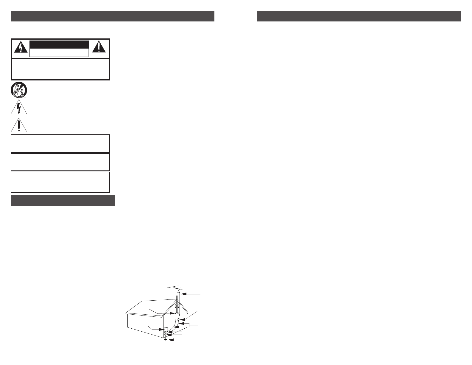
14. Outdoor Antenna Grounding—If an outside antenna or cable system is
connected to the product, be sure the antenna or cable system is grounded so as
to provide some protection against voltage surges and built-up static charges.
Article 810 of the National Electrical Code, ANSI/NFPA 70, provides information
with regard to proper grounding of the mast and supporting structure, grounding
of the lead-in wire to an antenna discharge unit, size of grounding conductors,
location of antenna-discharge unit, connection to grounding electrodes, and
requirements for the grounding electrode. See Figure A.
15. Lightning—For added protection for this product during a lightning storm, or
when it is left unattended and unused for long periods of time, unplug it from the
wall outlet and disconnect the antenna or cable system. This will prevent damage
to the product due to lightning and power-line surges.
16. Power Lines—An outside antenna system should not be located in the vicinity
of overhead power lines, other electric light or power circuits, where it can fall into
such power lines or circuits. When installing an outside antenna system, extreme
care should be taken to keep from touching such power lines or circuits as contact
with them may be fatal.
17. Overloading—Do not overload wall outlets, extension cords, or integral
convenience receptacles as this can result in a risk of fire or electric shock.
18. Object and Liquid Entry—Never push objects of any kind into this product
through openings as they may touch dangerous voltage points or short-out parts
that could result in a fire or electric shock. Never spill liquid of any kind on the
product.
19. Servicing—Do not attempt to service this product yourself as opening or
removing covers may expose you to dangerous voltage or other hazards. Refer
all servicing to qualified service personnel.
20. Damage Requiring Service—Unplug this product from the wall outlet and
refer servicing to qualified service personnel under the following conditions:
a. When the power-supply cord or plug is damaged,
b. If liquid has been spilled, or objects have fallen into the product,
c. If the product has been exposed to rain or water,
d. If the product does not operate normally by following the operating instructions.
Adjust only those controls that are covered by the operating instructions as an
improper adjustment of other controls may result in damage and will often require
extensive work by a qualified technician to restore the product to its normal
operation,
e. If the product has been dropped or damaged in any way, and
f. When the product exhibits a distinct change in performance—this indicates a
need for service.
21. Replacement Parts—When replacement parts are required, be sure the
service technician has used replacement parts specified by the manufacturer or
have the same characteristics as the original part. Unauthorized substitutes may
result in fire, electric shock or other hazards.
22. Safety Check—Upon completion of any service or repairs to this product, ask
the service technician to perform safety checks to determine that the product is in
proper operating condition.
23. Wall or Ceiling Mounting—The product should be mounted to a wall or ceiling
only as recommended by the manufacturer.
24. Heat—The product should be situated away from heat sources such as
radiators, heat registers, stoves, or other products (including amplifiers) that
produce heat.
NOTE TO CATV SYSTEM INSTALLERS:
THIS REMINDER IS PROVIDED TO CALL THE CATV SYSTEM INSTALLER'S
ATTENTION TO ARTICLE 820 - 40 OF THE NEC THAT PROVIDES
GUIDELINES FOR PROPER GROUNDING AND, IN PARTICULAR,
SPECIFIES THAT THE CABLE GROUND SHALL BE CONNECTED TO THE
GROUNDING SYSTEM OF THE BUILDING, AS CLOSE TO THE POINT OF
CABLE ENTRY AS PRACTICAL.
EXAMPLE OF ANTENNA
GROUNDING
GROUND
CLAMP
ELECTRIC
SERVICE
EQUIPMENT
NEC NATIONAL ELECTRIC CODE
POWER SERVICE
GROUNDING
ELECTRODE SYSTEM
(NEC ART 250, PART H)
ANTENNA
LEAD IN WIRE
ANTENNA
DISCHARGE UNIT
(NEC SECTION
810-20)
GROUNDING
CONDUCTORS
(NEC SECTION
810-21)
GROUND CLAMPS
Forward Path
Gain:
Gain Adjust Range:
Frequency Coverage:
Flatness:
Slope Adjust Range:
Noise Figure:
Impedance:
Return Loss-
Input:
Output:
Output Test Port:
Composite Triple Beat (CTB):
Cross Modulation (XMD):
Composite Second Order (CSO):
Maximum Output Level:
* Measured at +44 dBmV per channel with 77 channel loading.
Power Requirements-
Amplifier Unit:
Return Path
Configuration:
Frequency Range:
Return Loss:
General
Amplifier Type:
Operating Temperature:
Power Supply-
Input Power Rating:
Input Connection:
Output Power Rating:
Output Connection:
Amplifier Unit-
Enclosure:
Dimensions:
Shipping Weight:
SPECIFICATIONS 3
42 dB nominal, 40 dB minimum.
15 dB minimum.
54 - 550 MHz.
± 1.5 dB maximum.
Flat to greater than 15 dB tilt at 54 MHz.
6 dB typical, 7 dB maximum (at maximum gain setting).
75 Ohms.
16 dB typical, 14 dB worst case.
16 dB typical, 14 dB worst case.
-30 dB, ±2 dB.
-63 dB typical, -60 dB maximum*.
-65 dB typical, -62 dB maximum*.
-60 dB typical, -57 dB maximum*.
See channel loading chart on page 4.
24 VDC, 12 Watts Power supply included.
Passive, Insertion loss 2 dB typical, 4 dB maximum.
5 - 36 MHz.
16 dB typical, 14 dB worst case.
Push-Pull Hybrid Amplifier Module.
-200 C to +500 C (-40 F to +1220 F).
Included with amplifier.
100-120 VAC, 50/60 Hz.
3 wire line USA plug.
24 VDC, 700 mA.
Power cable with disconnect.
Extruded aluminum.
9” L, including connectors x 5.5” W x 2.5” H.
2.4 lbs., including power supply.
 Loading...