

DRAKE DD860 User Manual
1 DD860 DIGITAL DEMODULA TOR
TM
CONTROLS, INDICATORS AND CONNECTIONS 2
DIGITAL DEMODULATOR
CHANNEL
LOCK
ERROR
SNR
40 dB
15 dB
DD806
0 4
1
DIGITAL DEMODULATOR
CHANNEL
LOCK
ERROR
SNR
40 dB
15 dB
DD806
0 4
1
DIGITAL DEMODULATOR
CHANNEL
LOCK
ERROR
SNR
40 dB
15 dB
DD806
0 4
1
POWER SUPPLY
PS8
R.L. DRAKE COMPANY
230 INDUSTRIAL DRIVE
FRANKLIN, OHIO 45005 U.S.A.
CUSTOMER SERVICE AND PARTS TELEPHONE: +1 (937) 746-6990
TELEFAX: +1 (937) 743-4576
WORLD WIDE WEB SITE: http://www.rldrake.com
12 POSITION RACK MOUNT POWER SUPPLY
DD860 SATELLITE DEMODULATOR
TM is a trademark of the R.L. Drake Compan y
® is a registered trademark of the R.L. Drake Company
© Copyright 2003 R.L. Drake Company P/N: 3852380A-1-2003 Printed in the U.S.A.
The R.L. Drake model DD860 Digital
Demodulator is a professional quality modular
digital headend component designed to provide
optimum performance for VSB or QAM
demodulation. The DD860 receives an 8 VSB,
16 VSB, 64 QAM, or 256 QAM signal from a
terrestrial broadcast or CATV feed in the 54 to
858 MHz range, and demodulates the signal
providing an MPEG-2 digital transport stream
output.
The DD860 normally provides two 75 Ohm,
serial ASI outputs. A parallel SPI output is
available on special order.
Front panel signal to noise ratio and staus
indicators are provided.
A low phase noise tuner design provides
reliable operation with dense signal constellations such as 256 QAM or 16 VSB.
An NTSC co-channel rejection filter for VSB
modes is incorporated.
A wide range equalizer eliminates multipath
effects.
QAM modes incorporate auto selection of ITU
A (DVB) or ITU B (DigiCipher II)
FEC.
IRC and HRC channel plans are selectable by
moving an internal jumper.
The DD860 is designed to mount in the
DRMM12 rack mounting cage.
RF INPUT
POWER
SPI LVDS OUTPUT
13
1
25
14
+12 V GND +5 V
ASI TRANSPORT
STREAM OUTPUT
RF INPUT
POWER
SPI LVDS OUTPUT
13
1
25
14
+12 V GND +5 V
ASI TRANSPORT
STREAM OUTPUT
DIGITAL DEMODULATOR
CHANNEL
LOCK
ERROR
SNR
40 dB
15 dB
DD806
0 4
1
F2
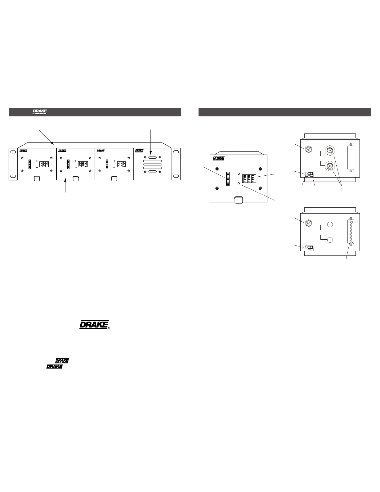
Figure 1
F3
F4
F1 - LOCK
This indicator shows that the demodulator is
receiving a valid digital signal and has locked
to it.
F2 - LED Signal-to-Noise Ratio Meter
Indicates the signal-to-noise ratio of the
received signal. The range is between 15 dB
and 40 dB. Threshold levels are nominally
15 dB for 8VSB, 29 db for 16VSB, 23 db for
64 QAM, and 28dB for for 256QAM. These are
minimum levels required for lock. Normal
operating levels must exceed threshold by
several dB to ensure reliable operation.
F3 - CHANNEL Selector Switch
This switch is used to enter the two or three
digit channel number. The range of numbers is
also used to determine the mode of operation.
F4 - ERROR
This indicator shows that the FEC is not able to
correct all errors in the received signal. Check
for a low signal-to-noise ratio or improper
antenna aiming if errors occur.
FRONT PANEL CONTROLS AND
INDICATORS
R1
R2
R1 - RF INPUT
This "F" type connector is the input for the
tuner. The DD860 will tune to all U.S.A. off air
broadcast frequencies or to standard EIA CATV
channels up to 858 MHz (channel 134).
R2 - DC Power Connector
This is the power input connector. Connect to a
Drake PS8 or equivalent power supply.
R3 - BNC Connectors (ASI output model)
These are the MPEG2 transport stream
outputs. The ASI (Asynchronous Serial
Interface) Output Impedance is 75 Ohms.
R4 - 25 Pin SPI LVDS OUTPUT Connector
(SPI output model)
This is the MPEG2 transport stream output.
The DVB Synchronous Parallel Interface levels
comply with low voltage differential signalling
specifications.
Figure 2 (ASI)
+12V GND +5
REAR PANEL CONNECTIONS
R4
Figure 3 (SPI)
R1
R2
R3
F1
3 INSTALLATION
DD860 CHANNEL SELECTION / CHANNEL CHARTS 4
The front panel channel selection switches are
used to select the mode of demodulation, the
desired band plan (CATV or Broadcast) and the
specific channel number. Four blocks of 133
channels each are allocated to CATV channels
and two blocks of 68 channels each are
allocated for off-air broadcast frequencies.
CATV channels in 64 QAM modulation are
selected using switch settings 002 through 134.
These switch settings correspond directly to the
EIA CATV channel numbers.
CATV channels in 256 QAM modulation are
selected using switch settings 202 through 334.
To determine the switch setting, add 200 to the
desired EIA CATV channel number.
CATV channels in 8 VSB modulation are
selected using switch settings 402 through 534.
To determine the switch setting, add 400 to the
desired EIA CATV channel number.
CATV channels in 16 VSB modulation are
selected using switch settings 602 through 734.
To determine the switch setting, add 600 to the
desired EIA CATV channel number.
Off-Air Broadcast channels in 8 VSB may be
tuned by selecting channels 802 through 869.
Add 800 to the broadcast channel number that
corresponds to the actual RF transmission
channel. Do not enter the virtual channel
number, used by some broadcasters.
NOTE: IRC and HRC CATV formats are
supported by setting of an internal jumper.
473
479
485
491
497
503
509
515
521
527
533
539
545
551
557
563
569
575
581
587
593
599
605
611
617
623
629
635
641
647
653
659
665
671
677
683
689
695
701
707
713
719
725
731
737
743
749
755
761
767
773
779
785
791
797
803
14
15
16
17
18
19
20
21
22
23
24
25
26
27
28
29
30
31
32
33
34
35
36
37
38
39
40
41
42
43
44
45
46
47
48
49
50
51
52
53
54
55
56
57
58
59
60
61
62
63
64
65
66
67
68
69
Center of Channel
Frequency (MHz)
UHF BROADCAST CHANNELS 8VSB
Channel
Number
OFF-AIR
814
815
816
817
818
819
820
821
822
823
824
825
826
827
828
829
830
831
832
833
834
835
836
837
838
839
840
841
842
843
844
845
846
847
848
849
850
851
852
853
854
855
856
857
858
859
860
861
862
863
864
865
866
867
868
869
DD860
Channel
57
63
69
79
85
177
183
189
195
201
207
213
2
3
4
5
6
7
8
9
10
11
12
13
Center of Channel
Frequency (MHz)
VHF BROADCAST CHANNELS 8VSB
Channel
Number
OFF-AIR
802
803
804
805
806
807
808
809
810
811
812
813
DD860
Channel
90-260 VAC
DC OUTPUTS X 8
12V GND 5V
RF INPUT
POWER
SPI LVDS OUTPUT 4
13
1
25
14
+12 V GND +5 V
ASI TRANSPORT
STREAM OUTPUT
RF INPUT
POWER
SPI LVDS OUTPUT 4
13
1
25
14
+12 V GND +5 V
ASI TRANSPORT
STREAM OUTPUT
RF INPUT
POWER
SPI LVDS OUTPUT 4
13
1
25
14
+12 V GND +5 V
ASI TRANSPORT
STREAM OUTPUT
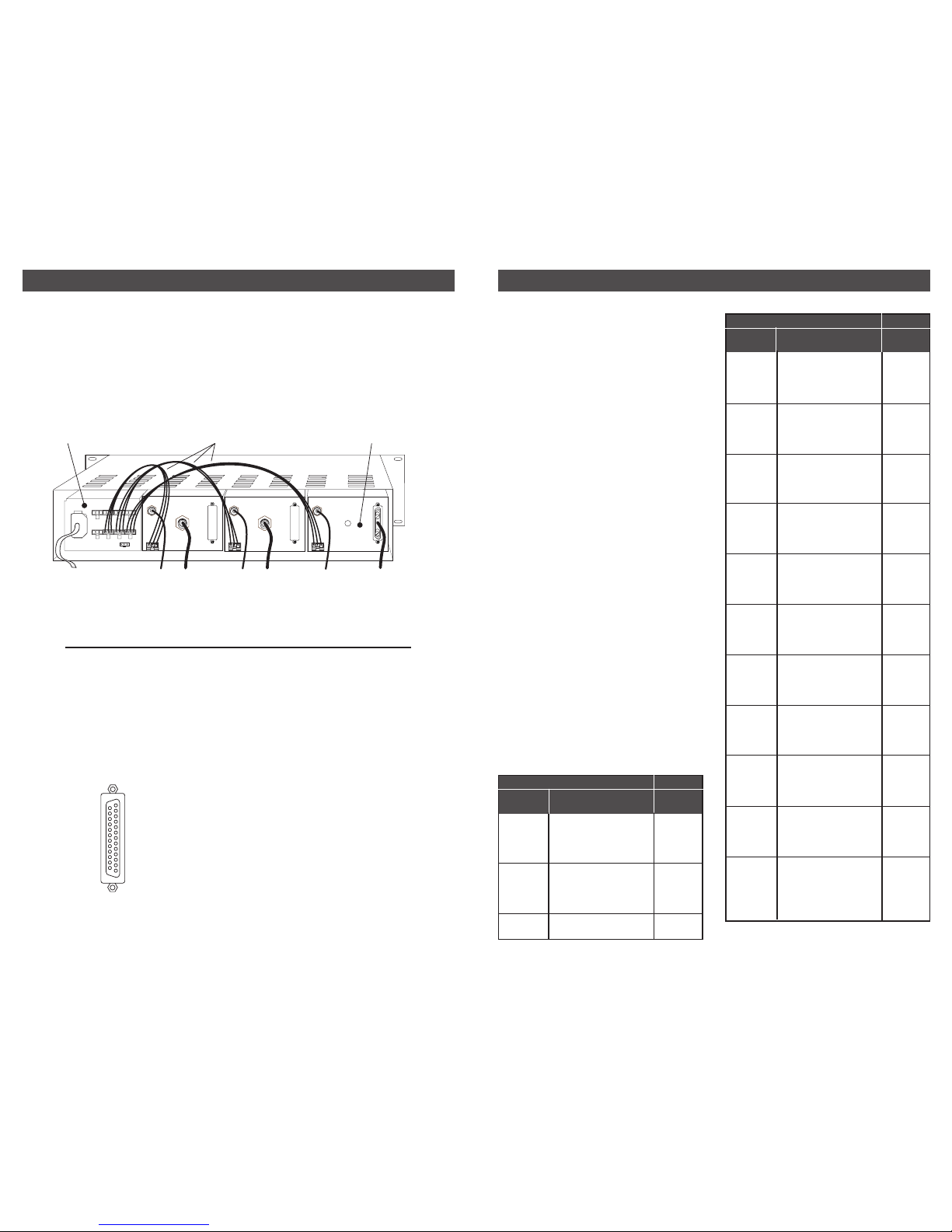
All connections to and from each module are
made through the rear panel. Refer to Figure 4
for correct cable and wiring connections.
RACK MOUNTING
Adequate ventilation is very important in
multichannel installations.
Figure 4
The DRMM12 frames should be spaced apart
vertically by at least 1 3/4" wherever possible.
Air movement is mandatory in enclosed rack
cabinets. Excessive heat will shorten
component life.
DD860
DEMODULATOR UNIT
AC POWER
CORD
FROM OFF-AIR
ANTENNA OR CATV
PS8 POWER SUPPLY
1 Data Clk +
2 GND
3 Data 7 +
4 Data 6 +
5 Data 5 +
6 Data 4 +
7 Data 3 +
8 Data 2 +
9 Data 1 +
10 Data 0 +
11 Data Valid +
12 Start of Packet +
13 GND
25
14
13
1
The DD860 is designed to mount into the
DRMM12 rack mounting enclosure.
The DD860 is four units wide. Power for the
DD860 should be supplied by the model PS8
power supply module which also mounts into
the DRMM12.
Pin Out DVB SPI Interface
14 Data Clk 15 GND
16 Data 7 17 Data 6 18 Data 5 19 Data 4 20 Data 3 21 Data 2 22 Data 1 23 Data 0 24 Data V alid 25 Start of Packet -
TO
QAM ASI
INPUT
TO
QAM SPI
INPUT
POWER SUPPLY CABLES
 Loading...