

Page 1
®
Rack Mount Distribution Amplifiers, with Power Doubled Hybrid Output 1
EPOLSNIAG
INPUT
MONITOR
-20 dB
MIN. MAX.
MIN. FLAT
F2 F3 F4 F5 F1
DESCRIPTION
The R.L. DRAKE models DAR8642, DAR8633, DAR8618,
DAR7542, and DAR7533, are broadband distribution
amplifiers designed for indoor headend use in both
residential and commercial buildings where RF signal
distribution in the frequency range of 47 to 860 MHz is
required. Each model, except the DAR8618, incorporates a
push-pull hybrid input preamp and a power doubled hybrid
output amplifier to provide a very low distortion signal for
launch amp applications in the output of an SMATV or CATV
headend. The Gain and Slope controls operate between the
preamp hybrid and the output hybrid to maintain a low noise
figure over a wide range of gain and slope settings.
Only the DAR8618 has a power doubled output hybrid with
no input preamp.
Input and output test connectors are provided for convenient
monitoring of the signal path. The amplifier circuitry is
designed for maximum stability, low distortion, low noise
figure, and is protected in a rugged aluminum housing. The
unit oper
ates from a nominal 100-240 VAC, 50/60 Hz input.
DAR DISTRIBUTION AMPLIFIER
POWER
OUTPUT
MONITOR
-20 dB
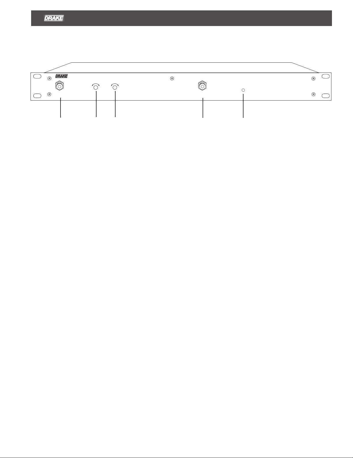
F1 - POWER LED
This indicator illuminates when power is supplied to the unit.
F2 - INPUT MONITOR
This connector may be used to monitor input to the DAR.
The levels will be 20 dB below the input levels at R3.
F3 - GAIN
Adjusts the amplifier interstage attenuator.
F4 - SLOPE
Adjusts the slope of the output signal.
F5 - OUTPUT MONITOR
This connector may be used to monitor the output of the
DAR. Levels will be 20 dB below those present at R2.
R2 must be terminated in 75 Ohms for an accurate reading.
Page 2
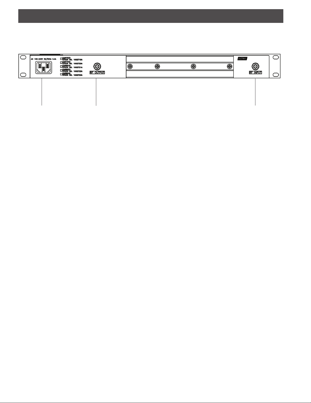
2 Rear Panel Connections
R1 R3 R2
R1 - AC LINE CORD
Connect this line cord to a 100-240V, 50/60 Hz AC power source.
R2 - RF OUTPUT
This is the RF output for CATV distribution and is the
amplified output of channels that are input to port R3 from
54 MHz and higher.
R3 - RF INPUT
This connector accepts the RF input from a headend
combiner output, 54 MHz and higher.
Page 3

INSTALLATION
1) Unpack the distribution amplifier.
2) Mount the amplifier in the desired location in the rack. Be
sure to leave at least one open rack space above and below
the amp to allow proper ventillation.
3) Connect input and output cables to the amplifier.
4) Plug the power line cord into a power source.
5) Preset slope control fully clockwise.
6) While monitoring the output levels at the Output Monitor
-20 dB test port, adjust the Gain control for desired output at
the high end of the band. Then monitor the lowest channel
and adjust slope control to equalize this channel to the
desired level (usually equal to but not higher than the high
end of the band). Since there can be a slight interaction
between the slope and gain settings, it is advised to repeat
this step a few times to ensure the desired levels are
attained.
NOTE: The -20 dB input and output test por ts can be used
to monitor input and output levels
when the load is connected to the amplifier output and
power is on.
. These are only accurate
Installation 3
A WORD CONCERNING INPUT LEVELS
It is important to keep the input level to the amplifier within
an optimum range. If the level is too high, higher nonlinear
distortion will result and if the level becomes too low, C/N
might be less than desired. As a general rule, stay within
the optimum input level range listed in the specifications.
The listed levels assume a fully loaded channel complement.
Higher levels may be used if the channel loading is less.
Page 4

4 Specifications and Warranty
SPECIFICATIONS COMMON TO ALL MODELS (unless otherwise noted)
Forward Gain Adjustment Range:
Slope Control Adjustment (54 MHz):
Input/Output Impedances:
Input and Output Monitor Ports:
Hum Modulation:
15 dB minimum
10 dB minimum
75 Ohms.
- 20 dB.
- 65 dB.
ADDITIONAL SPECIFICATIONS FOR SPECIFIC MODELS
DAR7533
1002719A
Frequency Coverage (forward path):
Forward Gain:
Noise Figure:
Return Loss, Input & Output:
Channel Loading:
47 to 750 MHz.
30 dB.
8 dB maximum.
14 dB.
110 CH.
Output Level (maximum per channel
for distortions listed below):
Input Level (maximum):
+36/44 dBmV.
+20 dBmV.
Optimum Input Level Range
for Best Performance:
+10 dBmV to
+15 dBmV.
Nonlinear Distortions-
Composite Triple Beat:
Composite Second Order:
Cross-modulation:
- 66 dB.
- 64 dB.
- 70 dB.
THREE YEAR LIMITED WARRANTY
R.L. DRAKE HOLDINGS LLC warrants to the original purchaser this product shall be free from defects in material or workmanship for
three (3) years from the date of original purchase.
During the warranty period R.L. DRAKE HOLDINGS LLC or an authorized Drake service facility will provide, free of charge, both parts
and labor necessary to correct defects in material and workmanship. At its option, R.L. DRAKE HOLDINGS LLC may replace a
defective unit.
DAR7542
1002720A
47 to 750 MHz.
42 dB.
6.5 dB maximum.
14 dB.
110 CH.
+44 dBmV.
+10 dBmV.
+0 dBmV to
+5 dBmV.
- 58 dB.
- 58 dB.
- 60 dB.
Power Requirement:
Operating
Temperature Range:
Weight:
DAR8633
1002722A
47 to 860 MHz.
30 dB.
dB maximum.
8.5
14 dB.
129 CH.
36/44 dBmV.
+18 dBmV.
+7 dBmV to
+12 dBmV.
- 62 dB
- 67 dB.
- 67 dB.
100-240 VAC, 50/60 Hz
- 20 deg. to + 60 deg. C.
Size:
19.00" W x 5.0” D x 1.75" H.
8 lb s. (3.6 Kg).
DAR8642
1002723A
47 to 860 MHz.
42 dB.
7 dB maximum.
14 dB.
129 CH.
+36/44 dBmV.
+7 dBmV.
-3 dBmV to
+2 dBmV.
- 62 dB.
- 67 dB.
- 67 dB.
DAR8618
1002721A
47 to 860 MHz.
18 dB.
7.5 dB maximum.
14 dB.
129 CH.
+40 dBmV.
+22 dBmV.
N/A
- 61 dB.
- 60 dB.
- 68 dB.
To obtain such a warranty service, the original purchaser must:
1. Retain invoice or original proof of purchase to establish the start of the warranty period.
Notify R.L. DRAKE HOLDINGS LLC or the nearest authorized service facility, as soon as possible after discovery of a possible
2.
defect, of:
3. Deliver the product to R.L. DRAKE HOLDINGS LLC or the nearest authorized service facility, or ship the same in its original
container or equivalent, fully insured and shipping charges prepaid.
Correct maintenance, repair, and use are important to obtain proper performance from this product. Therefore carefully read the
Instruction Manual. This warranty does not apply to any defect that R.L. DRAKE HOLDINGS LLC determines is due to:
All implied warranties, if any, including warranties of merchantability and fitness for a particular purpose, terminate three (3) years from
the date of the original purchase.
The foregoing constitutes R.L. DRAKE HOLDINGS LLC'S entire obligation with respect to this product, and the original purchaser
have no other remedy and no claim for incidental or consequential damages, losses or expenses. Some states do not allow limitations
on how long an implied warranty lasts or do not allow the exclusions or limitation of incidental or consequential damages, so the above
limitation and exclusion may not apply to you.
This warranty gives you specific legal rights and you may also have other rights which vary from state to state. This warranty shall be
construed under the laws of Ohio.
a) the model and serial number,
b)
the identity of the seller and the approximate date of purchase; and
c) A detailed description of the problem, including details on the electrical connection to associated equipment and
the list of such equipment.
1. Improper maintenance or repair, including the installation of parts or accessories that do not conform to the quality and
specifications of the original parts.
2. Misuse, abuse, neglect or improper installation.
Accidental or intentional damage.
3.
shall
®
R.L. Drake Holdings LLC
710 Pleasant Valley Drive
Customer Service and Parts Telephone: +1 (937) 746-6990
Fax: +1 (937) 806-1510 www.rldrake.com
® is a registered trademark of the R.L. Drake Holdings LLC © Copyright 2012 R.L. Drake Holdings LCC P/N: 651230400A Printed in China.
® is a registered trademark of the R.L. Drake Holdings LLC © Copyright 2012 R.L. Drake Holdings LCC P/N: Printed in China.
Springboro, Ohio 45066
20121005
1002719A. 1002720A. 1002721A. 1002722A. 1002723A.
 Loading...