

Drake DA8642, DA8632, DA7543, DA7533 Instruction Manual
®
Distribution Amplifiers 1
-30dB
MONITOR
HPF
FWD
AMP
FORWARD PATH INTERSTAGE
MAX
SLOPE
MIN
GAIN
FWD
AMP
FORWARD
PATH
FIXED
INPUT EQ
FIXED
ATT
INDOOR
DISTRIBUTION
AMPLIFIER
OUTPUT
DA7543
49-750 MHz
43 dB GAIN
POWER DOUBLED
P/N: 1002705
FLAT
MAX
HPF
LPF
INPUT
LPF
-30 dB
MONITOR
REVERSE
PATH
GAIN
MIN MAX
AMP
AMP
POWER 26VAC
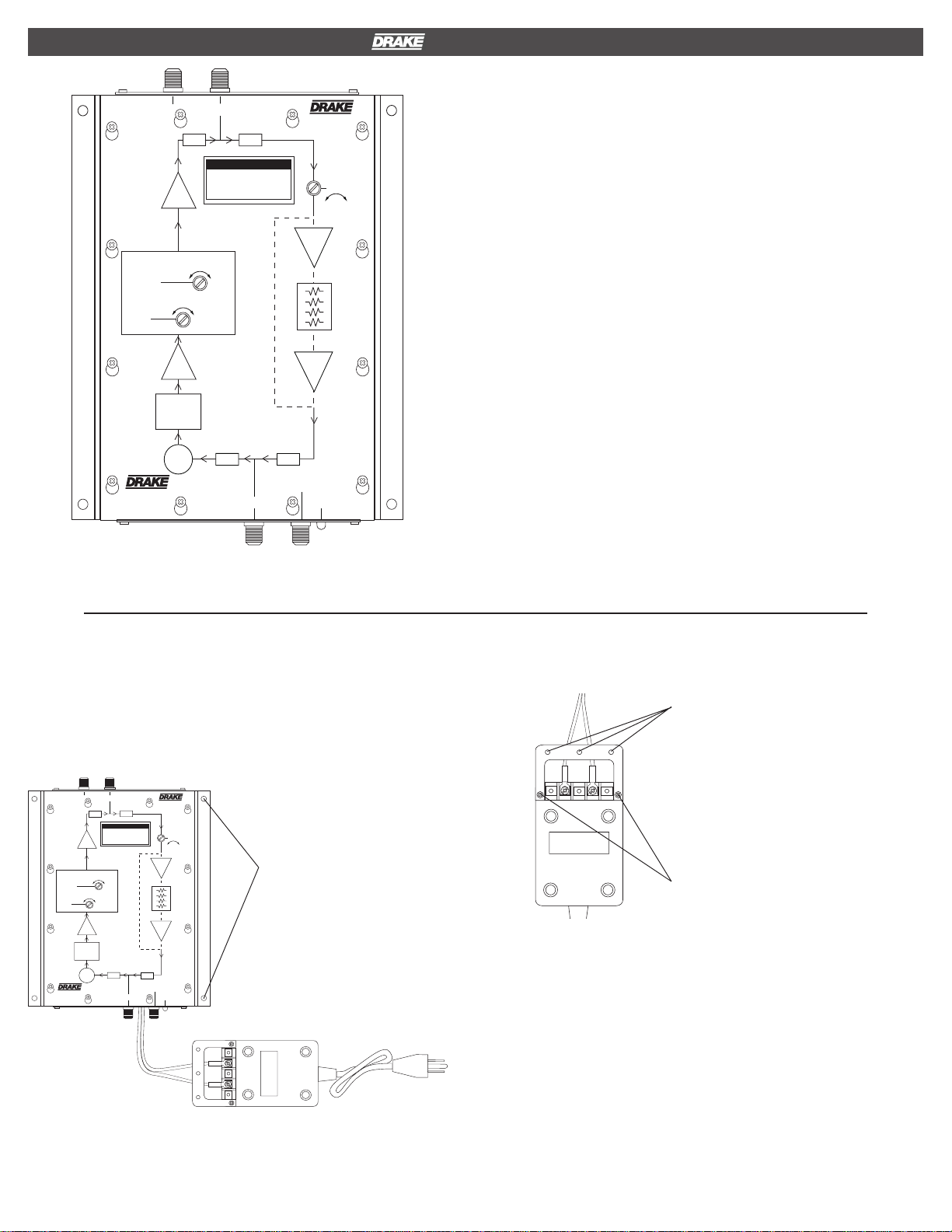
DESCRIPTION
The R.L. DRAKE models DA8642, DA8632, DA7543, and DA7533, are
broadband distribution amplifiers designed for indoor use in both residential
and commercial buildings where RF signal distribution in the frequency
range of 49 to 860 MHz is required. Each model provides a very low
distortion signal for a cable TV “drop”, the output of an SMATV headend, or
a small CATV headend. The Gain and Slope controls both have a range of
10 dB minimum and operate between the preamp hybrid and the output
hybrid to maintain a low noise figure over a wide range of gain and slope
settings. Double-sided, plated through hole, glass epoxy, printed circuit
boards, and SMT are used for low losses and maximum reliability.
All models include a 20 dB gain integrated active return path amplifier,
and can provide a nominal unity gain passive return or no return path by
selection with internal jumpers.
Input and output test connectors are provided for convenient monitoring of
the signal path. The amplifier circuitr y is designed for maximum stability,
low distortion, low noise figure, and is protected in a rugged aluminum
housing.
The unit operates from a nominal 26 VAC provided by the supplied
120 VAC, 60 Hz input AC Adapter.
Input equalizer and fixed attenuator options are available.
INSTALLATION
1) Unpack the distribution amplifier and AC adapter.
2) Mount the amplifier in the desired location, using the four mounting screw
holes on the sides of the amplifier. Vertical mounting on a wall with the
output end up is recommended for best ventilation and the coolest operation.
OUT
-30dB
MONITOR
OUTPUT
HPF
LPF
FWD
AMP
FORWARD PATH INTERSTAGE
MAX
SLOPE
MIN
GAIN
FWD
AMP
FORWARD
PATH
FIXED
INPUT EQ
FIXED
ATT
INDOOR
DISTRIBUTION
AMPLIFIER
POWER DOUBLED
FLAT
MAX
49-750 MHz
43 dB GAIN
HPF
DA7543
P/N: 1002705
REVERSE
PATH
GAIN
MIN MAX
AMP
SCREW HOLES FOR
WALL MOUNTING
(2 each side)
AMP
LPF
-30 dB
MONITOR
INPUT
POWER 26VAC
IN TRANSFORMER
1
2G4
5
4) If the power transformer is to be wall mounted, install the included
bracket as shown. Then mount transformer to the wall.
WALL MOUNTING HOLES
OF MOUNTING BRACKET
5
2G4
1
SCREWS FOR FASTENING
MOUNTING BRACKET
TO TRANSFORMER CASE
5) Connect input and output cables to the amplifier.
6) Plug the power transformer line cord into a 120 VAC/60 Hz
power source.
7) Preset slope control fully clockwise.
8) While monitoring the output levels at the Output -30 dB test port, adjust
the Gain control for desired output at the high end of the band. Then
monitor the lowest channel and adjust slope control to equalize this channel
to the desired level (usually equal to but not higher than the high end of the
band). Since there can be a slight interaction between the gain settings, it
is advised to repeat this step a few times to ensure the desired levels are
attained.
3) Route the power cable as needed to the power transformer. The cable
can be pushed between fins of the heat sink on the bottom of the amplifier.
Connect the power cable to the screw terminals on the power transformer.
NOTE: The -30 dB input and output test ports can be used to monitor input
and output levels. These are only accurate when the load is connected to
the amplifier output and power is on.
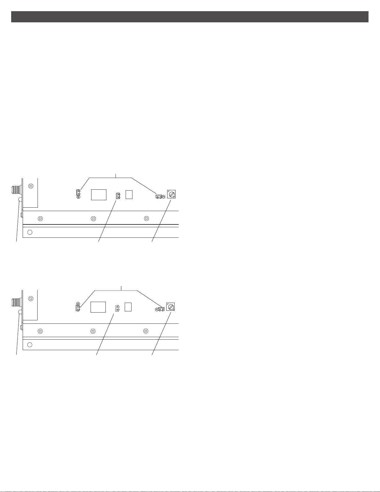
2 Internal Jumper Settings
RETURN PATH PROGRAMMING
There are three internal jumpers to be set. J1, J2, and J3. J1 and J3
program the signal path for the return path. If the return amplifier is
desired (20 dB gain), select the active return setting. This is the factory
default. If a unity gain return path is desired, select the passive return
settings. If no return path is desired, remove both J1 and J3. Jumper J2 is
used to enable DC power to the return amplifier. When selecting the active
return, Jumper J2 must be installed. If using the passive return or no
return, remove Jumper J2.
INTERNAL JUMPER SETTINGS -
1) Unplug amp from the AC power source.
2) Remove top cover by loosening (but not removing) the 12 top cover
screws. Slide the top cover so the screws will slip through the larger screw
hole openings, then remove top cover.
A) JUMPER SETTINGS FOR ACTIVE RETURN PATH (Factor y Setting)
J2
J1
J3
POWER LED
B) JUMPER SETTINGS FOR PASSIVE RETURN PATH
JUMPER INSTALLED
RETURN PATH GAIN
J2
J1
POWER LED
C) REMOVE ALL THREE JUMPERS FOR NO RETURN
JUMPER NOT IN-
STALLED
RETURN PATH GAIN
ADJUSTMENT
J3
ADJUSTMENT
 Loading...