

DRAKE 4000 series II Installation Manual


INSTALLATION GUIDE 4000 Digital Series ,,
Page iii of xii STA0379 - Issue 1.4
ACKNOWLEDGEMENTS
It is the policy of Drake Electronics Limited (hereafter referred to as
Drake
) to
continually improve the products and
Drake
reserves the right to modify product
specifications and characteristics without notice, at any time.
Every endeavour has been made to ensure that information, details and descriptions
set out in this literature are correct at the time of going to press. However
Drake
is
unable to guarantee that no changes have subsequently taken place to the
specification or ch aracteristics of, or relating to any
Drake
product, after the pu blication
of this literature.
Drake
shall not be liab le for any lo ss or dama ge whatsoev er arising
from the use o f any information, errors or omissions in this guide or any use of the
product.
E. & O.E. Correct at Time of Publication
Neither the whole, nor any part of the information contained herein, nor in the products
described in thi s guide, ma y be adapted o r reproduced i n any materi al form except with
the prior written approval of
Drake
.
MS-DOS and Windows 95/98 are registered trademarks of Microsoft Corporation.
Telos is a trademark of TLS Corporation.
Ethernet is a registered trademark of Xerox Corporation.
All correspondence relating to products or guides should be addressed to:
Technical Support
Drake Electronics Limited
The Hydeway
Welwyn Garden City
Hertfordshire
United Kingdom
AL7 3UQ
Tel:- +44 (0)1727 871200
Fax:- +44 (0)1707 371266
E-Mail:- techsupport@drake-uk.com
Website:- http://www.drake-uk.com
© 2000 All rights reserved.

4000 Digital Series ,, INSTALLATION GUIDE
STA0379 - Issue 1.4 Page iv of xii
WARNING
Electrical shock can cause severe personal injury or death. All
major units of this equipment are powered by mains voltage.
Unless specifically advised otherwise, DISCONNECT mains
supply before carrying out any maintenance or repair tasks.

INSTALLATION GUIDE 4000 Digital Series ,,
Page v of xii STA0379 - Issue 1.4
GLOSSARY OF TERMS
ADC Analogue to Digital Converter
ADM Assignment, Diagnostics and Monitoring
BNC Standard co-axial video connector
CODEC Coder/Decoder
CMAPSi Configuration and Master Assignment Programming System
integrated
Conference Facility configured by CMAPSi, similar to older Party Line sys-
tems.
CSU Central Switching Unit
DAC Digit a l to Ana l ogu e Co nve rt er
DAK Direct Access Key
dB Decibel
DPDT Double-Pole-Double-Throw
EPROM Erasable Programmable Read-Only Memory
GPI General Purpose Interface
GPSF General Purpose Special Function
Howlround Distorted audio - due to feedback of original signal in close
proximity.
I/O Input/Output
I/P Input
IFB Interruptable Foldback
Local Program-
ming
Modifying the DAK assignments via the Intelligent Control
Panel SOFT Mode
LCD Liquid Crystal Display
LED Light Emitting Diode
Listen Route An audio route to the Control Panel from a source. The audio
is normally heard on the Control Panel’s Loudspeaker or
Headset.
LS Loudspeaker
MB MegaByte
MHz Megahertz

4000 Digital Series ,, INSTALLATION GUIDE
STA0379 - Issue 1.4 Page vi of xii
N/C Normally Closed
N/O Normally Open
NID Non Intrusive Dow n l oad
NVRAM Non-Volatile Random Access Memory
O/P Output
PCB Printed Circuit Board
Pot. Potentiometer
PSU Power Supply Unit
RAM Random Access Memory
RCU Rear Connector Unit
RMS Root Mean Square
RU Standard Rack Unit (19 inches wide x 1.75 inches high or
482.6mm x 44.45mm)
Side tone Side tone is the audio, which is heard in the Headset’s ear-
piece, which is generated by the headset microphone. This
allows the operators to hear themselves when using head-
sets.
SPDT Single-Pole-Double-Thro w (switch / relay action)
SPST Single-Pole-Single-Throw (switch / relay action)
TA Terminal Adaptor
Talkback A Broadcast term referring to the intercom system.
Talk Route An audio route from the Control Panel to another destination.
The audio is normally generated from the Control Panel’s
main microphone or Headset microphone.
TBU Telephone Balance Unit
VOX Voice Operated Crosspoint (Xpt)
XLR Audio industry standard connector

INSTALLATION GUIDE 4000 Digital Series ,,
Page vii of xii STA0379 - Issue 1.4
Consult the named Drake document for further details.
Contact Drake for suitable options.
Tips given.

4000 Digital Series ,, INSTALLATION GUIDE
STA0379 - Issue 1.4 Page viii of xii

INSTALLATION GUIDE 4000 Digital Series ,,
Page ix of xii STA0379 - Issue 1.4
TABLE OF CONTENTS
TABLE OF CONTENTS ............................................................................................ix
1. INTRODUCTION .....................................................................................................1
1.1 System Overview ..............................................................................................1
2. GETTING STARTED ........... .... ..... ................................................... ..... ..... .............3
2.1 Unpacking the Equipment .................................................................................3
2.2 Installation .........................................................................................................3
2.2.1 General Information ...................................................................................3
2.2.2 Installing a System .....................................................................................4
2.2.3 Hot Insertion of Matrix Cards .....................................................................4
2.2.4 Pass Codes ...............................................................................................4
3. MATRIX DESCRIPTION ........................................... ..... .... .....................................5
3.1 4920 - 9RU Digital Matrix Frame ...................................................................... 5
3.1.1 Overview ....................................................................................................5
3.1.2 Matrix Rear Connections and Facilities .....................................................7
3.2 4420 - 4RU Digital Matrix Frame ...................................................................... 8
3.2.1 Overview ....................................................................................................8
3.2.2 Matrix Rear Connections and Facilities ...................................................11
3.3 Matrix Cards ....................................................................................................11
3.3.1 PDE4642 - Microprocessor Card .............................................................13
3.3.2 PDE4643 - Microprocessor Card RCU ....................................................16
3.3.3 PDE3601B Digital Matrix Card ................................................................20
3.3.4 PDE4606B - 16 Channel Panel Communications Card ...........................21
3.3.5 PDE4616 - 16 Channel Panel Communications Card RCU ....................22
3.3.6 PDE4621 - 16 Channel Audio Input / Output CODEC Card ....................23
3.3.7 PDE4631 - 16 Channel Audio Input / Output CODEC Card ....................25
3.3.8 PDE4622/PDE4622TX - 16 Channel CODEC Card RCU .......................27
3.3.9 PDE4628 - 16 Channel Serial Communications RCU .............................30
3.3.10 PDE4619 - General Purpose Interface RCU .........................................34
3.3.11 PDE4609 - 8 Channel Telephone Card RCU ........................................40
3.4 Matrix Power Supplies ....................................................................................46
3.4.1 4420 (4U) Matrix PD4172 Power Supply .................................................46
3.4.2 4920 (9U) Matrix PD4173 Power Supply .................................................47
3.4.3 Power Supply Redundancy .....................................................................48
3.4.4 Supply Protection .....................................................................................48
4. CONTROL PANEL DESCRIPTION ...................................................... ................49
4.1 Overview .........................................................................................................49
4.2 Standard Control Panels .................................................................................49

4000 Digital Series ,, INSTALLATION GUIDE
STA0379 - Issue 1.4 Page x of xii
4.2.1 PD4215 - 16 Key Control Panel (1RU) ....................................................49
4.2.2 PD4217 - Intelligent Control Panel (1RU) ................................................50
4.2.3 PD4211 LCD Key Panel (1RU) ................................................................52
4.2.4 PD4212 LCD Key and Rotary Encoder Panel .........................................53
4.2.5 PD4224 - Intelligent Control Panel (2RU) ................................................55
4.2.6 PD4225 - Router Control Panel (2RU) ....................................................56
4.2.7 PD4226 - 32 Key Control Panel (2RU) ....................................................58
4.2.8 PD4221 - LCD Key Panel (2RU) .............................................................60
4.2.9 PD4222 - LCD Key and Rotary Encoder Panel (2RU) ............................61
4.2.10 PD4222S - Supervisor Panel .................................................................63
4.2.11 PD4294 - Desktop Control Panel ...........................................................63
4.3 Extension Panels ............................................................................................65
4.3.1 4203 - Level Control Panel (1RU) ............................................................65
4.3.2 4206 - 20 Key Extension Panel (1RU) .....................................................66
4.4 Custom Control Panels ...................................................................................68
4.4.1 PD4216 - Custom Panel Interface (1RU) ................................................68
4.4.2 PDE3531 Custom Panel Card .................................................................69
4.5 Panel Connections ..........................................................................................74
4.5.1 Microphone Socket ..................................................................................74
4.5.2 Headset Socket .......................................................................................74
4.5.3 AC Mains Socket incl. Voltage Selector and Fuse ..................................74
4.5.4 PDE4536 Fibre Optic/Coax Options Card ...............................................74
4.5.5 PDE4537 Options Card ...........................................................................75
4.5.6 I2C Serial Interface Connector ................................................................76
4.5.7 Audio (B) Input / Output Connector .........................................................76
4.5.8 Extension Connector ...............................................................................77
4.5.9 DC Power Adaptor Connector .................................................................78
4.5.10 DC Power Adaptor Ratings ....................................................................78
4.6 Control Panel Adjustments .............................................................................78
5. COMMISSIONING ............................. ................................................... ..... .... .......79
5.1 Matrix ..............................................................................................................79
5.1.1 Mains Supply ...........................................................................................79
5.1.2 Hot Insertion of Matrix Cards ...................................................................79
5.2 Control Panels ................................................................................................80
5.2.1 Mains Supply ...........................................................................................80
5.2.2 Applying Power ........................................................................................80
5.3 Normal Operation ............................................................................................82
5.4 Functional Checks ..........................................................................................82
5.5 Hardware Configuration ..................................................................................82
6. SYSTEM PROGRAMMING ...................................... ..... .......................................83
7. CABLING ............................................... ..... ................................................... ..... ..84
7.1 Mains Wiring ...................................................................................................84

INSTALLATION GUIDE 4000 Digital Series ,,
Page xi of xii STA0379 - Issue 1.4
7.2 Control Panel Wiring .......................................................................................84
7.2.1 Solid conductor coaxial cable ..................................................................84
7.2.2 RJ45-Terminated Cabling ........................................................................85
7.3 PDE4537 Options Card ..................................................................................87
7.3.1 PDE4537 Control Interface ......................................................................87
7.3.2 PDE4537 Audio Interface ........................................................................88
7.4 Matrix to PC Download Cable .........................................................................89
7.5 PD3901 Beltpack Interface ...........................................................................89
7.5.1 Installation Information .............................................................................90
8. INTRODUCTION TO DRAKE SYSTEM NETWORKING ....................................93
8.1 Overview .........................................................................................................93
8.2 General System Requirements .......................................................................94
8.2.1 Personal Computer Attachment ...............................................................95
8.3 Installation .......................................................................................................95
8.3.1 DCS3000/4000 Series .............................................................................95
8.3.2 4000 Series II ...........................................................................................97
8.4 System Interconnection ..................................................................................97
8.4.1 Overview ..................................................................................................97
8.4.2 Audio Networks ........................................................................................98
8.4.3 Connecting CMAPSi to Ethernet .............................................................98
9. SYSTEM SPECIFICATIONS .................................... ..... .......................................99
INDEX .....................................................................................................................105

4000 Digital Series ,, INSTALLATION GUIDE
STA0379 - Issue 1.4 Page xii of xii

INSTALLATION GUIDE 4000 Digital Series ,,
Page 1 of 107 STA0379 - Issue 1.4
1. INTRODUCTION
1.1 System Overview
The 4000 Series II is a Digital Communications System using a central switching matrix
for routing calls between outstations connected in a star format.
The digital centra l switching matrix use s a microp rocessor fo r control a nd configur ation
purposes. A Digital Matrix Card, allowing multiple routes to be made simultaneously
achieves all switching and routing. Analogue audio, GPI inputs and outputs, data
interfaces and an advanced software package are also provided as part the 4000
Series II system.
A range of Digital Control Panels is available provi ding a suitable user interface for
making and receiving calls over the system. These panels contain push buttons
configured to operate specific routes or activate control functions. The key actions are
sent as digital data using a serial link to the central matrix for interpretation by the
microprocessor and info rmation is r eturned to the control pa nel by th e same me thod.
Audio is sent and received digitally, multiplexed with the data via a single co-axial
cable. Audio and data can also be connected via standard twisted pair wiring and
CAT5.
The standard control panels provide the basic facilities of Direct Access Keys (DAKs)
which allow single-bu tton operation for freque nt calls, a Reply key for respondi ng to
unscheduled calls and where applicable, a dial display for making infrequent calls.
A call is initiated on a control p anel by pressing o ne of the assi gned DAKs or, o n panels
equipped with an electronic dial keypad, by dialling a number and pressing the call
button. This activates crosspoints, located in the Matrix, which make the audio route
(or routes) to the desir ed destination(s) . Routing can be one -way (e.g. talk onl y) or twoway (talk and listen simultaneously) and several callers can speak to the same
destination at the same time due to the mixing capability of the matrix.
The crosspoints in the matrix are activated or de-activated according to configuration
rules held in the system’s Matrix map (stored in the microprocessor’s memory). The
system map for the 4000 Series II residing on a Personal Computer is downloaded into
the Matrix from the ’Configuration and Master Assignment Programming System
integrated’ (CMAP Si) and control s every aspect of 4000 Series II oper ation inclu ding a
comprehensive diagnostic facility. The Matrix sends part of the system map out to
each control p anel, programming the actions available on each DAK of each panel.
This includes any special function that may also be assigned to a particular pushbutton
in addition to initiating the normal dual routing.
Each DAK may be centrally configured and assigned to a destination, source or both
at system set-up. On some panels, DAKs that are not assigned at system set-up can
be assigned , by local programming of the pushbuttons in Soft mode , to allow different
routing options. Local assignments may not be retain ed if the system is reset, although
they are held in non-volatile memory at the panel and thus will be retained after power
down.
Destinations and sources can be other panels, beltpacks, 2-wire or 4-wire circuits,
either individually or in gr oups. The destinati ons an d sources coul d also be i n anoth er

4000 Digital Series ,, INSTALLATION GUIDE
STA0379 - Issue 1.4 Page 2 of 107
talkback system. Connection to other 4000 Series II systems can also be achieved by
use of Ethern et, providing an integrat ed private intercom net work. Up to eight 4000
Series II systems can be connected using this facility.
A Conference facility is also available, configured via CMAPSi, which allows people to
converse in a conference mode. This is similar in operation to the Conference Ring
(Party Line) facilities available in older conventional systems. Users can be allowed
access to any conference (up to 64 conferences are allowed) either to liste n on ly or to
talk and liste n.
Contact Drake for details on networking.
CMAPSi operation details are given in CMAPSi on-line help

INSTALLATION GUIDE 4000 Digital Series ,,
Page 3 of 107 STA0379 - Issue 1.4
2. GETTING STARTED
2.1 Unpacking the Equipment
All 4000 Series II Systems are tested prior to dispatch to ensure correct oper ation.
Each system assembly should be inspected for damage during transit. Any damage
should be reported to Drake Electronics Ltd or their appointed representative.
2.2 Installation
2.2.1 General Information
It is necessary to have sufficient space at the front and the rear of the equipment bay
holding the matrix to allow easier access during installation.
It is also assumed that the cor r ect ca bles a nd ca bl e l e ngt hs ha ve b een determined for
the installation of the control panels and externals. It is advisable to have all cable runs
completed prior to fitting the system into the equipment bays.
The physical and electrical requirements f or each part of th e system are detailed in this
guide.
Drake
recommends the use of a Fan Tray, such as the Drake PD3704, with the 9RU
frames as forced cooling is required.
WARNING
Risk of electrical shock. All installation operations must be
completed before applying mains AC power to the system.
Suitably qualified personnel conversant with current electrical
safety requirements should perform the installation.
The mains safety earth connection to each item of equipment
must be maintained at all times during operation of this system.
Ensure that the AC supply to the digital routing matrix matches
that required by the power supply units installed (the maximum
power rating is marked on the rear of each matrix).

4000 Digital Series ,, INSTALLATION GUIDE
STA0379 - Issue 1.4 Page 4 of 107
CAUTION:
Adequate ventilation must be provided to avoid serious overheating of the
module components when the PSUs are operated at high currents or in enclosed
equipment bays. Forced air-cooling must be used to maintain the internal
temperature of the PSUs below 70°C.
2.2.2 Installing a System
The installation should be conducted in the following order:
1. Prepare all cables for the system as described in this Installation Guide.
2. Install the Matrix into a suitable cooled 19" wide rack bay.
3. Install the Control Panels in the correct locations and connect the cables and
mains supply, but do not switch the supply on.
4. Install the Power Supply Unit(s) in to the matrix frame, ensuring that the correct
supply is fitted to the correct slot.
5. Connect all of the cables to the matrix, but do not move the positions of cards or
their RCUs from the factory positions.
Note: The PC to Matrix connection should be made using the cable supplied by
Drake with the Matrix.
6. Check the Earth connection and mains AC supply is installed to current electrical
safety requirements.
7. Follow the procedure in the Commissi oning section of this Installation Guide.
8. Switch on the power to the Control Panels and check that the LED indication is as
described in this guide.
9. Check the cards in the matrix for the correct LED signalisation.
10. If the system needs to be programmed, a PC will need to be connected to the
matrix.
2.2.3 Hot Insertion of Matrix Cards
All 4000 Series Euro-cards and power supplies may be inserted or removed without
causing damage.
2.2.4 Pass Codes
The 4000 Series II matrices have a passcode to enable system sizes and features
bought with your system. The pass code is supplied either inside the front door of the
4RU or 9RU matrix and/or on the purchase documentation.
From the CMAPSi Map Menu select Show Current Passcodes and edit the default
entry of 0000-0000-0000-0000 to the passcode which is specific to your system.
INSTALLATION GUIDE 4000 Digital Series ,,
Page 5 of 107 STA0379 - Issue 1.4
3. MATRIX DESCRIPTION
3.1 4920 - 9RU Digital Matrix Frame
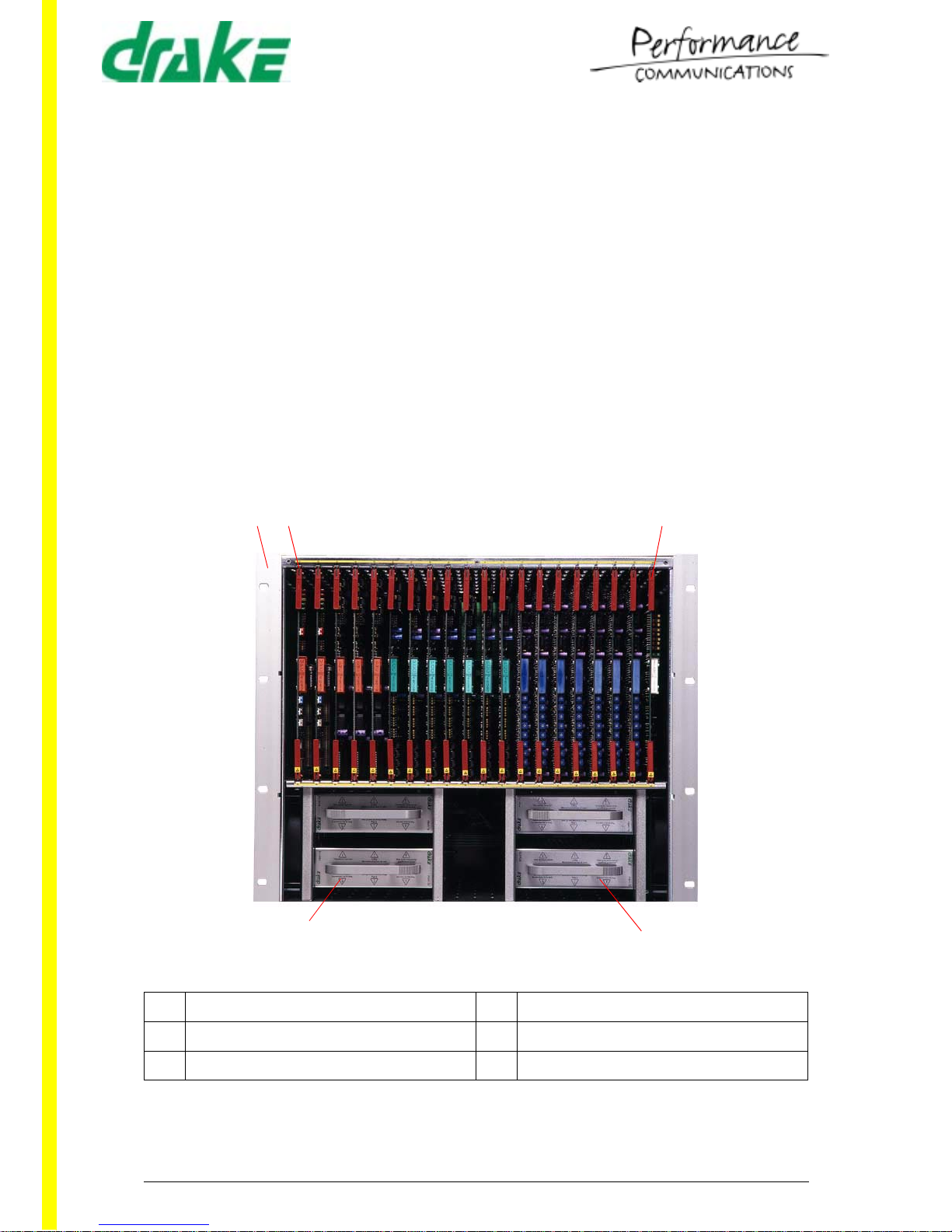
3.1.1 Overview
The 4920 Series matrix comprises a 9U by 19 inch rack mount unit with all connections
made from the rear of the frame. The Matrix power supply section comprises of plugin PSUs, connected via two standar d IEC connectors to the mai n supply. Access to the
plug-in circuit cards is via the front of the frame, most cards having a corresponding
rear connector unit fitted, accessed from the rear of the matrix.
Forced air cooling, with a 2U gap above the unit is required to maintain the unit at the
correct operating temper atures.
Drake
recommends the use of a Fan Tray, such as the
Drake PD3704. Inadequate or obstructed ventilation may result in serious damage to
the system.
3.1.1.1 Front View
1 Rack Mounting Ears 4 Power Supply
2 Card Slot 1 5 Power Supply Slot 4
3 Card Slot 20
12 3
4
5

4000 Digital Series ,, INSTALLATION GUIDE
STA0379 - Issue 1.4 Page 6 of 107
3.1.1.2 Rear View
3.1.1.3 Matrix Internal Backplane
One single backplane is employed in interconnecting the Matrix cards. This is for
power, audio and control.
3.1.1.4 Matrix Card Slots
Slots 1 and 2 are dedicated for PDE4642 Processor Cards, with the master in slot 2
and the slave, if fitted, in slot 1. There is only one slot in the rear of the matrix for the
associated PDE4 643 Rear Connector Unit (only one required) and this is RCU slot 2.
Slots 3 to 20 ar e used for combinations of PDE4606B Panel Communicatio n Card,
PDE4621 CODEC Card and PDE3601B Digital Matrix Card.
The RCU slots are utilised by the PDE4616 Panel Communications Card RCU,
PDE4622 CODEC RCU, PDE4628 Serial Communications RCU and PDE4 619 GPI
RCU. The position of these cards is set at build time and recorded in the System
Configuration. The card mnemonic and Drake part number are printed onto the
1 RCU Slot 2 5 Mains Fuse 1
2 RCU Slot 20 6 IEC Mains Inlet 1
3 Alarm Connector 7 Mains Fuse 2
4 Earthing point 8 IEC Mains Inlet 2
12
3
4
5
6
7
8
INSTALLATION GUIDE 4000 Digital Series ,,
Page 7 of 107 STA0379 - Issue 1.4
centrally mounted handle of each card. The slot number into which the card fits is
printed onto a label mounted on the top ejector handle of the card.
3.1.1.5 Matrix Power Supply Slots
Four power supply slots are p rovided at the bo ttom of the rack and are accessibl e from
the front. The slots are for the PDE4173 +/-5V, +/-12V supply.
3.1.2 Matrix Rear Connections and Facilities
The following connector details show the fixed chassis mounted pin-outs.
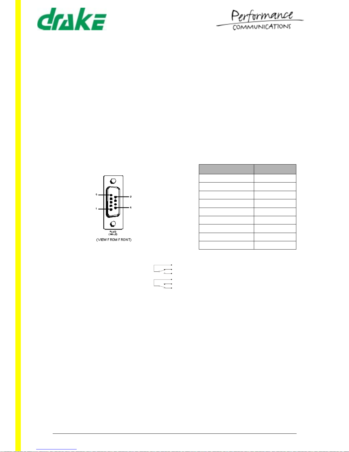
3.1.2.1 Alarm Connector
The 4920 matrix power supply system is fitted with an alarm facility, which detects the
failure of any power supply or voltage rail.
3.1.2.2 Earthing Point
The Earthing Point comprises of the chassis earth terminal for connection to external
equipment, for the provision of a common earth reference.
3.1.2.3 Mains Fuse
Two of these are prov ided as A C inp ut pr ote ction for e ac h of t he A C inle ts. The fuse
ratings are:
120V AC 6.3A T (anti-surge)
240V AC 3.15A T (anti-surge)
DESCRIPTION PIN NO.
Pole 1
N/O 2
N/C 3
+5V 4
Tech 0V 5
+12V 6
-12V 7
-5V 8
Chassis 9
P Pole (Common)
N/O Normally Open
N/C Normally Closed
P Pole (Common)
N/O Normally Open
N/C Normally Closed
POWERED
STATE
FAIL/OFF
STATE

4000 Digital Series ,, INSTALLATION GUIDE
STA0379 - Issue 1.4 Page 8 of 107
3.1.2.4 IEC Mains Inlet
Two of these are p rovide d for redu ndan t pow er op erat ion. Each o ne i s ra ted a t 90V t o
250V, 50Hz - 60Hz , 3 00 W m axi m um. Pri or t o co nne c ti on c h eck t h at t h e co rr ect fus e s
are present in the fuse holders as indicated above.
3.2 4420 - 4RU Digital Matrix Frame
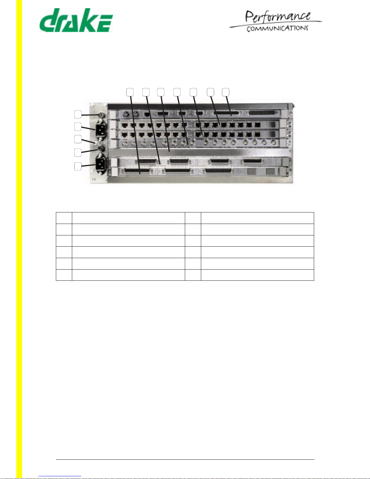
3.2.1 Overview
The 4420 Series matrix comprises a 4U by 19 inch rack mount unit with all connections
made from the rear of the frame. The Matrix power supply section comprises of plugin PSUs, connected via two standar d IEC connectors to the mai n supply. Access to the
plug-in circuit cards is via the front of the frame, most cards having a corresponding
rear connector unit fitted, accessed from the rear of the matrix.
A fan is built in providing a cooling flow from left to right when viewed from the front.
Inadequate or obstructed ventilation may result in serious damage to the system.
3.2.1.1 Front View
1 Rack Mounting Ears 6 Card Slot 3
2 Card Slot 7 7 Card Slot 2
3 Card Slot 6 8 Card Slot 1
4 Card Slot 5 9 Power Supply Section
5 Card Slot 4
INSTALLATION GUIDE 4000 Digital Series ,,
Page 9 of 107 STA0379 - Issue 1.4
3.2.1.2 Rear View
1 RCU Slot 7 7 RCU Slot 1
2 RCU Slot 6 8 Mains Fuse 1
3 RCU Slot 5 9 EC Mains Inlet 1
4 RCU Slot 4 10 Earthing point
5 RCU Slot 3 11 Mains Fuse 2
6 RCU Slot 2 12 EC Mains Inlet 2
1
2
3
4
5
6
7
8
9
10
11
12
4000 Digital Series ,, INSTALLATION GUIDE
STA0379 - Issue 1.4 Page 10 of 107
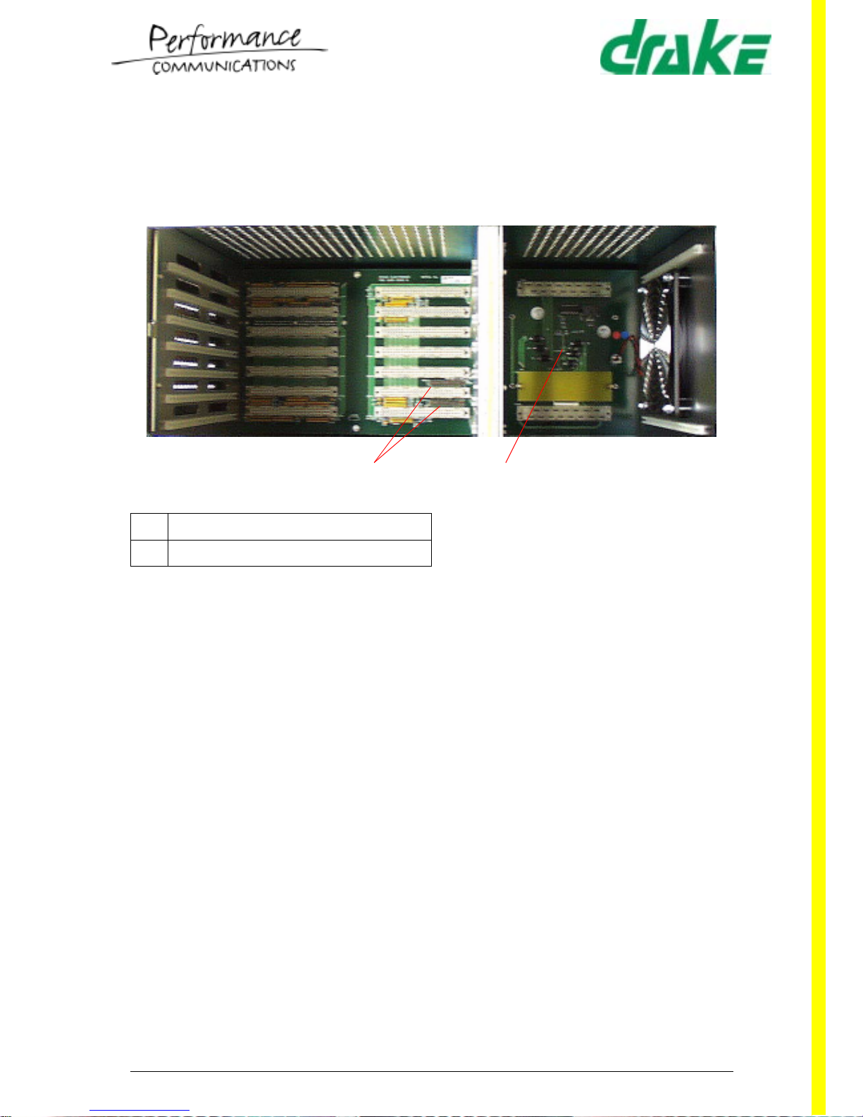
3.2.1.3 Matrix Internal Backplane
One backplane is empl oyed to interconne ct the Matrix cards. The backplane distribut es
the audio, control and power. The clock and bus termination circuits are also
implemented on this backplane.
The 4420 Matrix backplane Jumper Links are used to enable slot 6 to be fitted with a
slave PDE6642 Microprocessor Card. A Header Block is fitted over the Jumper Links
to ensure that the correct links are made.
NOTE: 4420 Matrix can only support either a Slave Microprocessor or Ethernet
networking capability.
The PSU Fail LEDs indicate the status of each Power Supply Unit when connected.
The green LED is illuminated when the Power Supply Unit is functioning correctly.
3.2.1.4 Matrix Card Slots
Slot 1 is dedicated for the PDE4 642 Proce ssor and RCU slot 1 in the rear of the matrix
for the associated PDE4643 RCU.
Slots 2 to 7 are used for combinations of PDE4606B Panel Communication Card,
PDE4621 CODEC Card and PDE3601B Digital Matrix Card.
The RCU slots are utilised by the PDE4616 Panel Communications Card RCU,
PDE4622 CODEC RCU, PDE4628 Serial Communications RCU and PDE4 619 GPI
RCU. The position of these cards is set at build time and recorded in the System
Configuration. The card mnemonic and Drake part number are printed onto the
centrally mounted handle of each card. The slot number into which the card fits is
printed onto a label mounted on the top ejector handle of the card.
1 Jumper Links
2 PSU Indicator LED
12

INSTALLATION GUIDE 4000 Digital Series ,,
Page 11 of 107 STA0379 - Issue 1.4
3.2.1.5 Matrix Power Supply Slots
Two power supply slo ts are prov ided on t he right of th e rack and a re acces sible fro m
the front. Both suppli es are iden tical an d both are u sed fo r redunda ncy. Mai ns Inlet 1
operates with the top supply and Mains Inlet 2 operates with the bottom supply. The
PDE4172 supplies are used in this frame to provide +/-5V and +/-12V.
3.2.2 Matrix Rear Connections and Facilities
3.2.2.1 Earthing Point
The Earthing Point comprises of the chassis earth terminal for connection to external
equipment, for the provision of a common earth reference.
3.2.2.2 Mains Fuse
Two of these are provided as AC input protection for each of the AC inlets. The fuse
ratings are:
120V AC 6.3A T (anti-surge)
240V AC 3.15A T (anti-surge)
3.2.2.3 IEC Mains Inlet
Two of these are provided for redun da nt po w er oper a tion. Each one is rated at 90V to
250V, 50Hz - 60Hz , 3 00 W m axi m um. Pri or t o co nne c ti on c h eck t h at t h e co rr ect fus e s
are present in the fuse holders as indicated above.
3.3 Matrix Cards
The following tabl e indicates the ca rds that can be i nstalled in the 40 00 Matrix with a
description of their functions:
Table 1: Matrix Card Types
NUMBER TYPE FUNCTION
PDE4642 Processor Card Central processor for matrix system.
PDE4643 Processor RCU Rear Connector Unit (RCU) for Processor
Card.
PDE3601B Digital Matrix Card Performs all of the audio routing functions.
PDE4606B Panel Communications
Card
Allows the connection of up to 16 Control
Panels.
PDE4616 Panel Communicati ons
RCU
Rear Connector Unit for Panel Communica-
tions Card with connection for up to 16 Con-
trol Panels via BNC connectors.
PDE4621B CODEC Card Allows the connection of up to 16 analogue
audio inputs and outputs.
4000 Digital Series ,, INSTALLATION GUIDE
STA0379 - Issue 1.4 Page 12 of 107
Important Note: All connector and pin information given in the following section s for the
above card types relates to the fixed connectors and not to the free (cable)
connectors.
PDE4622 CODEC RCU
(PDE4622 = electronic,
PDE4622tx = TXF)
Rear Connector Unit for CODEC Card with
connection for up to 16 audio inputs and out-
puts via D-Type connectors.
PDE4628 Serial Communi cations
RCU
Rear Connector Unit for CODEC Card with
connection for up to 16 audio and 16 RS232/
422 data inputs and outputs via 16 RJ45 con-
nectors.
PDE4619 GPI RCU Rear Connector Unit providing 32 opto-iso-
lated inputs, 12 open c ollector output s and 20
relay contact closure outputs via 37 way D-
Type connectors.
PDE4609 Telephone Interface
Card RCU
Interface for up to 8 Telos telephone balance
units.
Table 1: Matrix Card Types
NUMBER TYPE FUNCTION
INSTALLATION GUIDE 4000 Digital Series ,,
Page 13 of 107 STA0379 - Issue 1.4
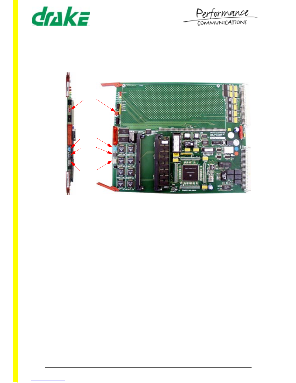
3.3.1 PDE4642 - Microprocessor Card
The PDE4642 provides the centralised functions of command, control and
communications, within the 4000 Series II System. It is used in conjunction with the
PDE4643 Rear Connector Unit (RCU).
PDE4642 Microprocessor Card and Coloured Reset Buttons
3.3.1.1 Card Location
The master processor card is located into slot 2 of the 4920 matr ix or slot 1 of the 4420
matrix.
The slave (if fitted) is to be located in slot 1 of the 4920 or slot 2 of the 4420 matrix.
3.3.1.2 Controls and Indicators
The PDE4642 processor is fitted with 16 LEDs, in four groupings:
1. Optional LEDs
The top 5 which are op tion al fit men t (tw o red, o ne yell ow, two green) are us ed fo r
special diagnostic purposes.
2. Power/DMC LEDs
The next group of four are:
+ve and -ve power indication.
DMC daughter board operation (optional fitment).
Red
Blue
Black
Grey
4000 Digital Series ,, INSTALLATION GUIDE
STA0379 - Issue 1.4 Page 14 of 107
3. PDE4642 Processor LEDs
The group of five LEDs, MGB [red], M/C [red], IPC [yellow], D16 [yellow] and OK
[green] operate as follows:
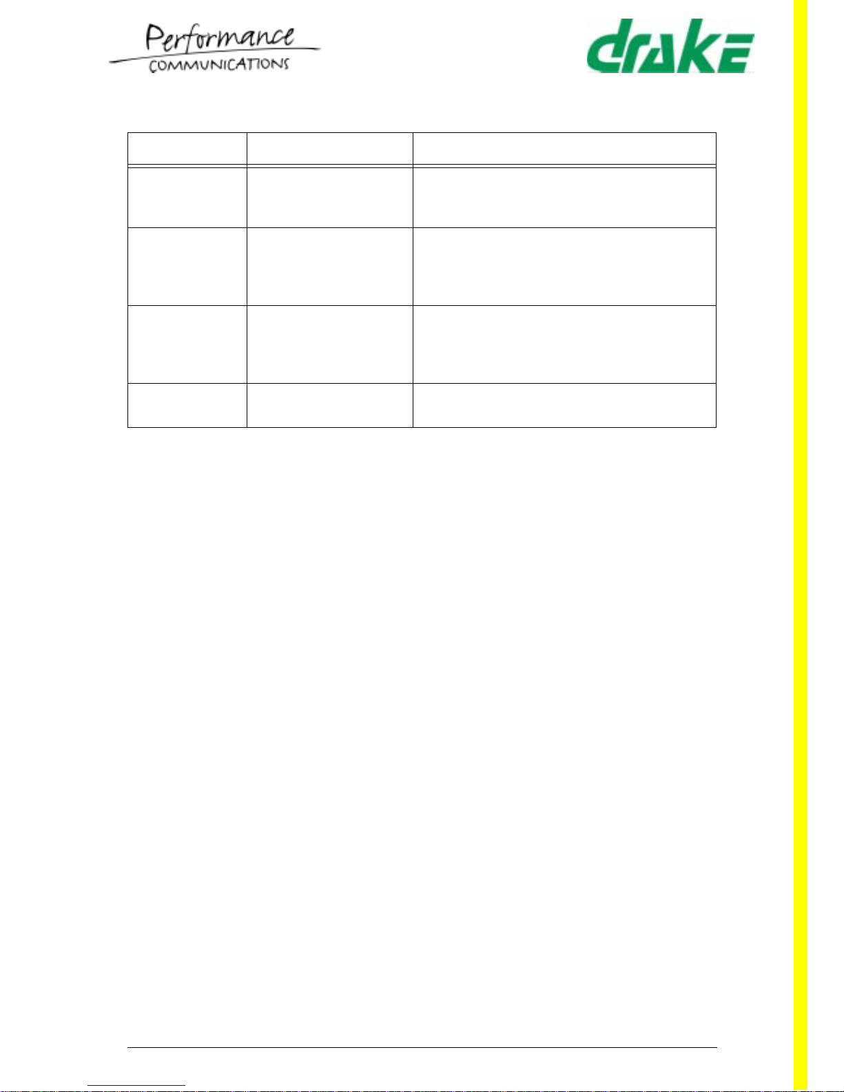
LED TYPE STATE DURING BOOT ASSIGNMENT IN MAIN CODE
MGB
Off On when processor card is master.
M/C
On, while downloading or
waiting for download of code.
On when external communications
(to ADM/CMAPSi) is enabled.
IPC
Flashes codes as detailed in
first table below.
Indicates communication to slave
processor.
D16 (Controlled by
Hardware configuration of rack).
Shows rack confi gur ed f or sp l it
O/P Bus Operation.
Shows rack configured for split O/P
Bus Operation.
OK
On Flashes codes as defined in second
table below.
Table 2: Operation of IPC LED During Boot Cycle
Slow flash with M/C LED off Processor is performing memory tests (after
Black button reset).
Short ‘blink’ at approx. 1Hz with 1:4 Mark :
Space ratio) with M/C LED On.
No application code present waiting for
download to start.
Moderate flash (approx. 1Hz) with M/C LED
On.
Download in progress.
Rapid (approx 2Hz) flash 50 : 50 Mark
Space.
Error has occurred (usually no application code
present when second processor present
prevents download).
Table 3: Operation of OK LED During Normal Operation
Short ‘blink’ at approx. 1Hz with 1:4
Mark : Space ratio) with M/C LED On.
Using PROM or back-up MAP.
Moderate flash (approx. 1Hz). Normal operation using ‘NVRAM’ main map.
Double flash for 1-2 seconds immediately
after Reset or Download/Reset.
Preparing/checking MAP.
Double flash continues permanently. No valid MAP present (Waiting for MAP
download if MGB and M/C LEDs are also on).

INSTALLATION GUIDE 4000 Digital Series ,,
Page 15 of 107 STA0379 - Issue 1.4
4. Ethernet LEDs
The pair of LEDs below the grey button are Ethernet Tx/Rx LEDs.
3.3.1.3 Resets
There are four levels of reset available and these are:
1. Red Push-button - Power Up/Reset Sequence (Warm Start)
On power-up or when the red RESET push button is pressed the Master Processor Card checks the validity of the Standard Map data set configuration.
If the Standard Map data set proves to be invalid, the Master Processor Card
checks the validity of the data set h eld in th e Reserve Map ; this is u sed if it is valid.
The LED will flash at 1Hz at a 20/80 mark/space ratio.
If neither data set is valid, then the system will not commence operation. The
green LED will ’double flash’ at 1Hz at a 20/20/20/40 mark/space rati o.
Powering up will restore all previously latched keys and audio routes. (Note that
configuration changes can cause the panel keys to enable different audio routes).
2. Black Push button - Cold Start
Press the red and black push-button on the Processor Card(s). Then release the
red button while still pressing the black button. When the green LED begins to
flash, release the black button.
This causes the reset of the complete system; latched keys and audio routes are
cleared down (lost).
WARNING - Any local panel programming is also lost throughout the whole
system.
3. Blue Push button - Reserve Map Start
Press the red and bl ue push-button on the Process or Card(s). Then release the
red button while still pressing the blue button. When the green LED begins to
flash, release the blue button.
This reset forces the system to use the Reserve Map data set. If the Rese rve Map
set proves invalid, the system will not commence operation and this is ind icated by
the double-flash sequence on the green LED.
WARNING - Any local panel programming is also lost throughout the whole
system.
4. Grey Push button - Not in use
Reserved for Drake diagnostic purposes.

4000 Digital Series ,, INSTALLATION GUIDE
STA0379 - Issue 1.4 Page 16 of 107
5. Bootstrapping
Press the red, blue and bla ck push- button on the Pr ocessor C ard(s) . Then re leas e
the red button while still pressing the blue and black buttons. When the green LED
begins to fla sh, release the blue and black buttons.
Control Panels will have firmware dow nloaded from the Master Processor Card.
This process is known as bootstrapping.
WARNING - Allow the Black/Blue reset to complete its operation before
attempting another reset. This could lead to the bootstrap process not being
completed successfully.
WARNING - Any local panel programming is also lost throughout the whole
system.
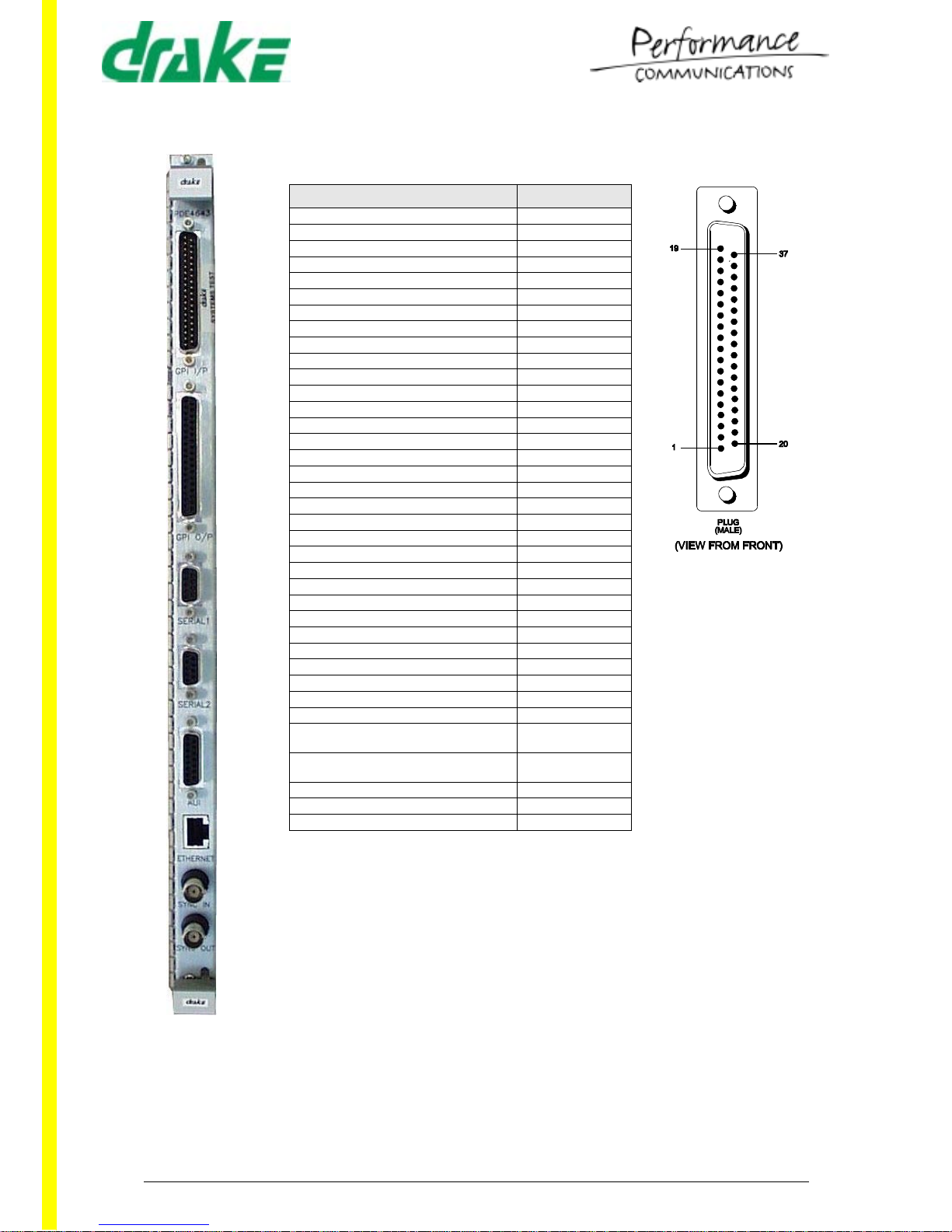
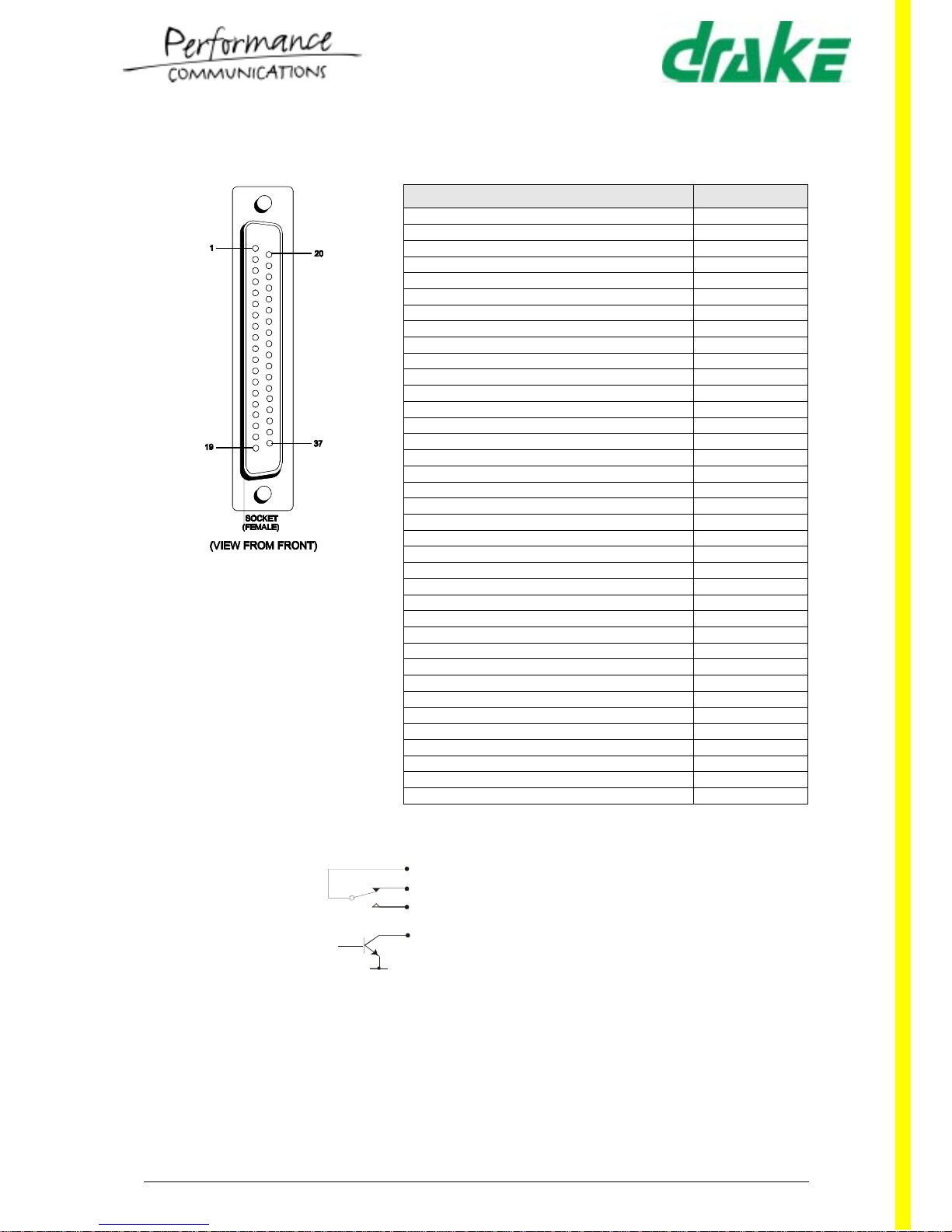
3.3.2 PDE4643 - Microprocessor Card RCU
The PDE4643 RCU provides connection to the RS232 (two 9-way socket D-type
connector) port s availa ble o n the M icropro cess or cards (PDE46 42). O nly on e RCU is
required per matrix rack.
It also provides a 15-way D-type AUI interface and a RJ45 Ethernet twisted pair
connection.
The BNC “sync” connectors provided are for synchronising different matrices together
for future digital trunk connections.
Two 37-way D-types provide GPI connection when the GPI daughter card (PDE4645)
is fitted (optional).
3.3.2.1 Card Location
One of these cards must be located in RCU slot 2 the 4920 matrix, or RCU slot 1 in the
4420 matrix.
INSTALLATION GUIDE 4000 Digital Series ,,
Page 17 of 107 STA0379 - Issue 1.4
Table 4: PDE4643 - GPI Inputs (Optional)
Description Pin Number
GPI Input 1 1
GPI Input 2 20
GPI Input 3 2
GPI Input 4 21
GPI Input 5 3
GPI Input 6 22
GPI Input 7 4
GPI Input 8 23
GPI Input 9 5
GPI Input 10 24
GPI Input 11 6
GPI Input 12 25
-7
-26
-8
-27
-9
-28
-10
-29
-11
-30
-12
-31
-13
-32
-14
-33
-15
-34
-16
-35
Isolated Inputs (requires external +7
Volts to +24 Volts applied)
17
Isolated Inputs (requires external +7
Volts to +24 Volts applied)
18
Common 24V Return 19
Tech 0 Volts 36
Tech 0 Volts 37
4000 Digital Series ,, INSTALLATION GUIDE
STA0379 - Issue 1.4 Page 18 of 107
Table 5: PDE4643 - GPI Outputs (Optional)
Description Pin Number
Relay Output 1 P 1
Relay Output 1 N/C 2
Relay Output 1 N/O 3
Relay Output 2 P 4
Relay Output 2 N/C 5
Relay Output 2 N/O 6
Relay Output 3 P 7
Relay Output 3 N/C 8
Relay Output 3 N/O 9
Relay Output 4 P 10
Relay Output 4 N/C 11
Relay Output 4 N/O 12
Relay Output 5 P 13
Relay Output 5 N/C 14
Relay Output 5 N/O 15
Relay Output 6 P 16
Relay Output 6 N/C 17
Relay Output 6 N/O 18
Tech 0 Volts 19
Relay Output 7 P 20
Relay Output 7 N/C 21
Relay Output 7 N/O 22
Relay Output 8 P 23
Relay Output 8 N/C 24
Relay Output 8 N/O 25
Relay Output 9 P 26
Relay Output 9 N/C 27
Relay Output 9 N/O 28
Relay Output 10 P 29
Relay Output 10 N/C 30
Relay Output 10 N/O 31
Relay Output 11 P 32
Relay Output 11 N/C 33
Relay Output 11 N/O 34
Relay Output 12 P 35
Relay Output 12 N/C 36
Relay Output 12 N/O 37
P Pole (Common)
N/C Normally Closed
N/O Normally Open
Direct DC Control Output
INSTALLATION GUIDE 4000 Digital Series ,,
Page 19 of 107 STA0379 - Issue 1.4
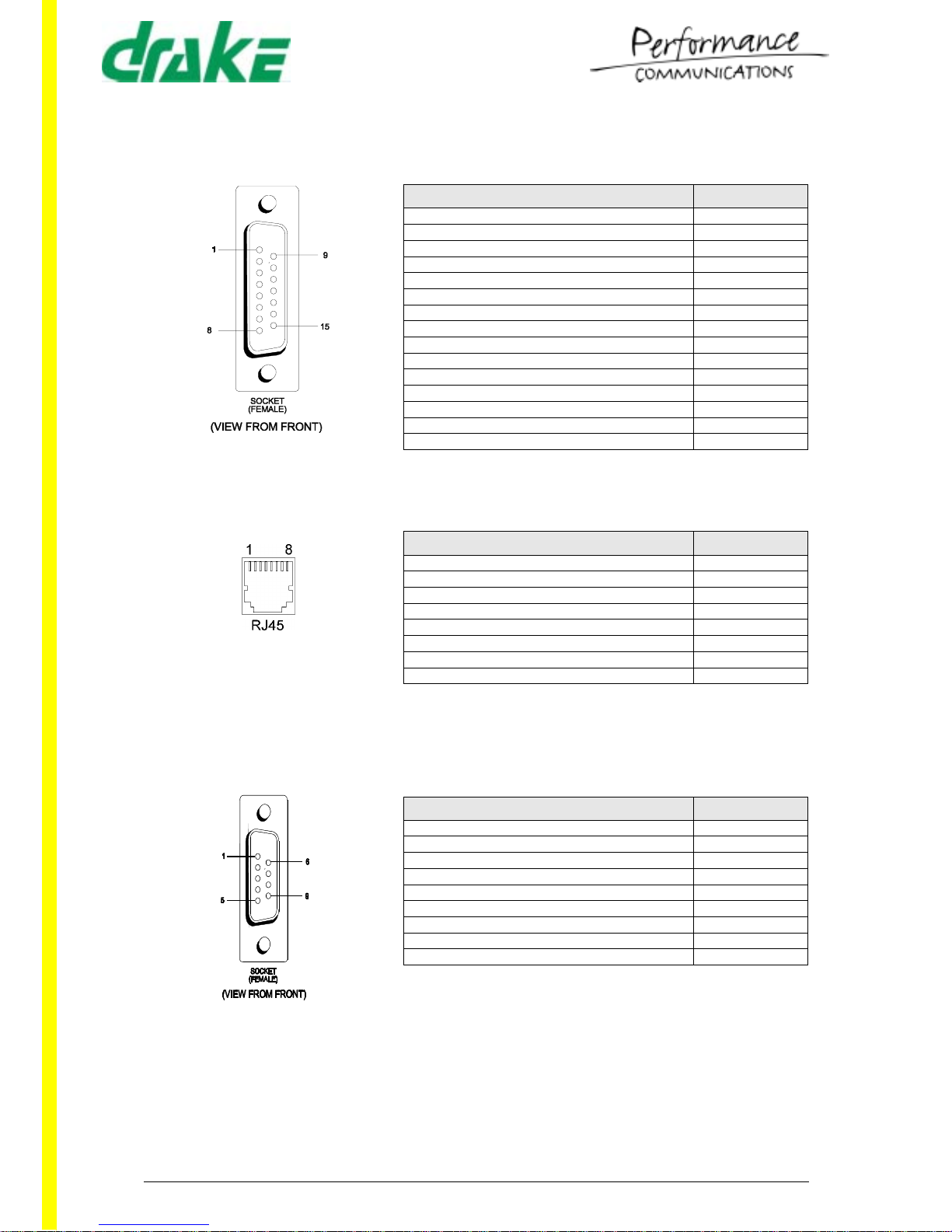
Table 6: PDE4643 - AUI
Description Pin Number
Control Input Screen 1
Control Input + 2
Data Output + 3
Data Input Screen 4
Data Input + 5
DC Power 0V 6
-7
-8
Control Input - 9
Data Output - 10
Data Output Screen 11
Data Input - 12
DC Power +12V 13
DC Power Screen 14
-15
Table 7: PDE4643 - Ethernet RJ45
Description Pin Number
Data Transmit (TD+) 1
Data Transmit (TD-) 2
Data Receive (RD+) 3
-4
-5
Data Receive (RD-) 6
-7
-8
Table 8: PDE4643 - Serial 1 and 2
Description Pin Number
-1
Data Receive (Rx) 2
Data Tran sm it ( Tx) 3
-4
Screen 5
-6
-7
-8
-9
 Loading...