

DRAKE 1002366 User Manual
Installation 2
INTRODUCTION
The 1002366 board is used to process the
transport stream after satellite demodulation and before QAM modulation. It
enables the FIXED CLOCK mode of
operation (AUTO CLOCK mode is still
selectable), performs PCR correction, and
it also provides an ASI output of the
demodulated transport stream.
TRANSPORT STREAM PROCESSING
The transport stream processing feature
of the 1002366 board will add null packets
if the SCT860 is set to the FIXED CLOCK
mode and the demodulated transport
stream data rate is less than the rate set
as the fixed output rate. The 1002366 can
also drop extra null packets from the
transport stream when required to obtain
the desired output rate.
The standard SCT860 does not modify the
transport stream - Drake labels this mode
the ‘AUTO CLOCK’ mode as the output
rate is automatically determined by the
received input signal data rate. When the
SCT860, with the 1002366 installed, is set
to the AUTO CLOCK mode setting, it
operates as if the board were not installed;
the null packets will not be processed and
neither dropping or adding will occur.
The 1002366 option board must be
installed into the SCT860, and the
SCT860 firmware must be updated, in
order to activate the FIXED CLOCK mode.
The null packet processing functions are
enabled in the FIXED CLOCK mode. The
AUTO CLOCK mode can still be selected
in the menu.
When the SCT860, with the1002366
board, is set to the FIXED CLOCK
setting, all null packets will be dropped
from the demodulated transport stream.
The rate is then built back up, by adding
1
TM
Model 100-2366 Packet Processing/ASI TS Output Option Board (SCT860)
null packets, to the fixed output QAM
symbol (baud) rate that is set via the front
panel. Dropping null packets is required in
some cases in order to bring the rate
down to or below the desired rate when
the satellite uplink may add extra null
packets.
PCR CORRECTION
The SCT860 performs PCR correction on
the processed transport stream before
QAM modulation when the SCT860 is
used with the 1002366 option and is set
up in the FIXED CLOCK mode. No PCR
adjustments are made when the unit is set
to the AUTO CLOCK mode.
ASI OUTPUT
The 1002366 option board also adds an
ASI transport stream output connector to
the SCT860. A chassis mount type BNC
connector with coaxial cable is provided
for those who have a requirement for this
feature. The ASI output will be the demodulated satellite signal transport stream
output, without processing. It is provided in
DVB ASI format.
This output may be used to feed the
satellite signal transport stream to a
multiplexer where part of the stream may
be needed for remultiplexing with another
stream for another output channel.
If ASI output is not a requirement, place
the connector assembly in a storage
location for possible future use.
If the ASI output feature is desired, plug in
the supplied BNC connector cable to the
SCT860 PC board as indicated in Figure 3
and mount the BNC connector in the rear
panel mounting hole. If your SCT860
does not have this hole, it must be added.
The unit can be returned to the Drake
Service Department, if necessary, for this
installation.
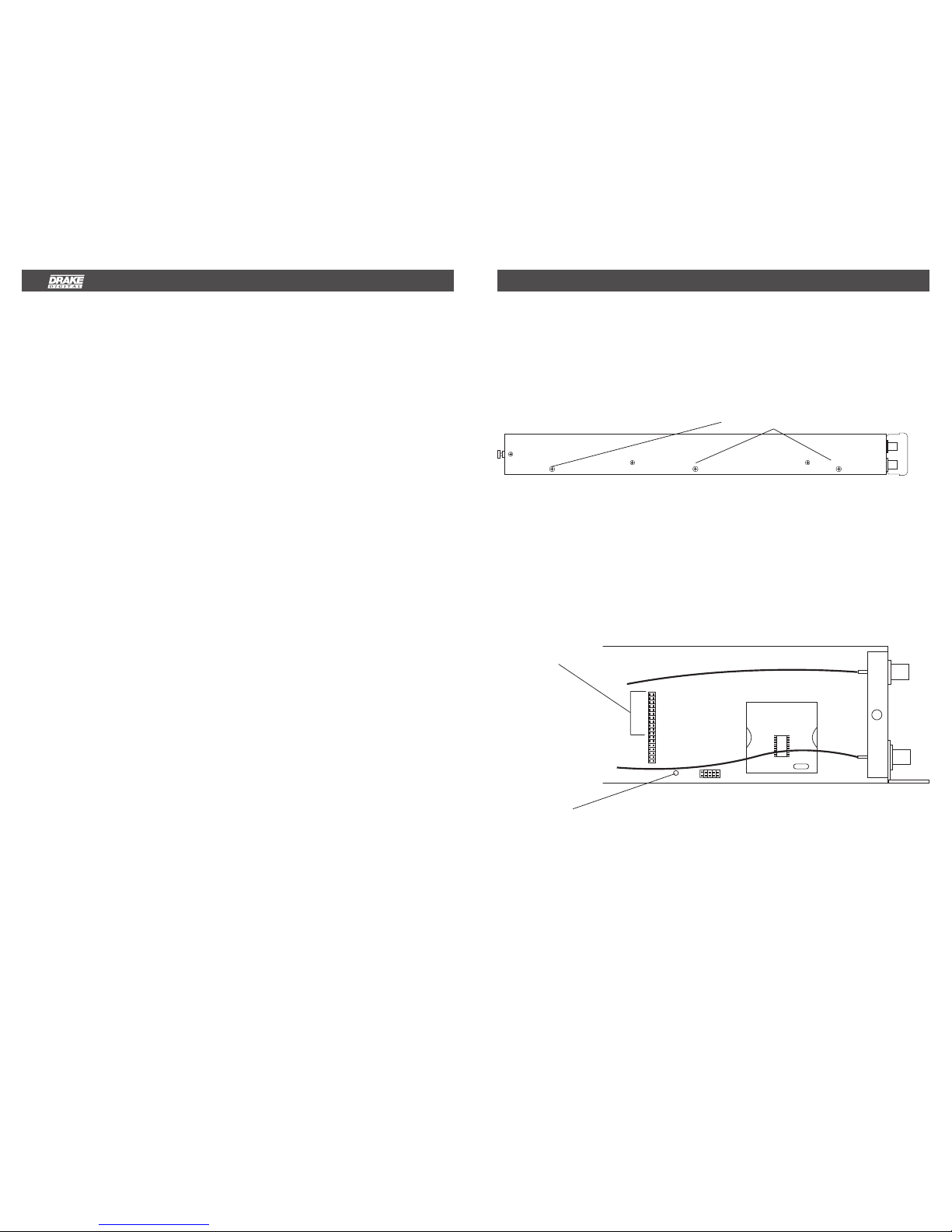
INSTALLATION IN THE SCT860
Looking at the SCT860 from the front panel,
observe the right side of the unit.
Remove the three top screws as shown,
three side screws, and three bottom screws
holding the right side of the case.
3 TOP SCREWS
Remove the right side and then lay the
transcoder on a flat surface laying on its left
side.
Locate the 36 pin interface connector and
remove the 11 jumpers that are in place.
Keep these jumpers for future use in case
the 100-2366 board is ever removed.
REMOVE 11 JUMPERS FROM THE 36 PIN CONNECTOR
LOCATION A
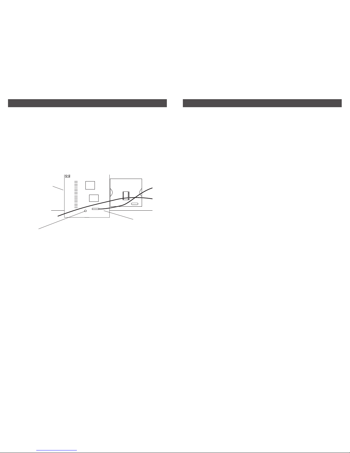
Remove the original screw at location A.
Screw the standoff spacer, that is included
with the option board, into the hole at
location A. Carefully remove the 100-2369
board from its static protection package.
Position the board as indicated and plug it
into the 36 pin connector.
Reinstall the screw to fasten the Option
Board to the spacer. Replace the right
side cover and screws.
OPERATION
Follow the instructions in the SCT860
instruction manual. Now that the 100-2366
board is installed, the FIXED clock option
may be selected and the output BD RATE
(baud rate which is the symbol rate) may
be set. The original AUTO clock mode is
still selectable, if desired.
Operation 4
3
Installation, continued
TIGHTEN SCREW
INTO SPA CER
PLUG INTERFA CE
HEADER INTO 36 PIN
CONNECTOR
FIGURE 3
PLUG IN SUPPLIED
BNC CONNECTOR
CABLE HERE
2) Copy the two files from the diskette
included with the 1002366 board kit
into the folder on your PC where the
SCT860 Control Program was
installed. If you did not change the
setting upon installation, this folder
should be: C:\Program Files\Drake
SCT860. Copy both the Fixed
Version 1.4 or higher hex file for use
with the 1002365 and also the Auto
Version 1.4 or higher hex file for use
if the 1002366 board is ever removed
from the SCT. These files may also
be found on V 1.4 or higher of the
SCT860 Digital Headend Transcoder
Remote Control Software CDROM.
3) If you do not have the diskette or V
1.4 or higher CDROM, referenced
above, you may use files found on the
V 1.2 or V 1.3 CDROM, but these are
not the latest versions. If using files
from these older CDROMs, select the
V 1.x fixed file. When these files are
used, the F will not display on the
front panel when the firmware version
is checked – therefore, we discourage
the use of these older versions unless
these are the only available option at
hand. Look for the presence of the
CLOCK selection menu to confirm
that the older fixed version of the
firmware is loaded after downloading.
UPDATE FIRMWARE
In order for the fixed clock option, provided
by the 1002366 board, to operate in the
SCT860, it is necessary to change the
firmware in the SCT860 to the fixed clock
version. Unless your SCT860 was ordered
from the factory with the 1002366 board
installed, you will need to download the
correct firmware to the SCT860. This will
be accomplished by means of the RS232
PC interface on the PS100 power supply.
The fixed clock firmware is provided on
the enclosed diskette.
Once the fixed clock firmware and the
1002366 board have been installed, either
the fixed clock mode or the auto clock
mode may be chosen from the SCT860
menu. Installation of the board and
firmware does not prevent use of auto
clock mode if desired.
1) Check current firmware version by
pressing the front panel up arrow
button while the SCT860 is not in
the adjust mode. Read the version
number. If you see VERSION 1.3,
VERSION 1.4, or an earlier version
without an F after the number, this
is auto clock mode only firmware
and must be upgraded for the
1002366 board to function. If you
see VERSION 1.4A or higher with an
"A" suffix, this is also auto clock
firmware and must be replacedwith
the fixed clock version. The 1002366
board can be installed with the auto
versions of the firmware in place and
the SCT will function as before in the
auto clock mode. No access to fixed
clock mode will be possible. If you
see VERSION 1.4 F or a later
version with an F suffix, you already
have the correct firmware (highly
unlikely unless the 1002366 board
is already in place because use of
the ‘F’ firmware without the
1002366 board is not allowed).
 Loading...