

Page 1

OWNER’S MANUAL
AUTOMATIK SERIES
For an online version of this manual
(readable with a smart phone)
Page 2

SAFETY ORDERS
When using an electronic appliance, basic safety precautions should always be followed. Read all guidelines
before operating the unit.
To reduce risk of fire, electric discharges or injuries :
• Use this vacuum only for its intended use as described in this manual. (Use of attachments not recommended by
manufacturer may cause fire, electric shock, injury or damage to system components.)
• Do not allow vacuum to be used as a toy. Close supervision is necessary when this vacuum is used by or near children.
• Do not leave the unit running without any supervising. Disconnect the unit if it is not used and before maintenance.
• Do not vacuum drywall dust or baking flour as it may cause damage to your vacuum.
• Avoid picking up hard or sharp objects to prevent damaging or block the hose and the plastic pipes.
• Do not put any object into openings. Do not use with any opening blocked. Keep free of dust, lint, hair and anything
that may reduce air flow/suction. Lack of air flow will cause the motor to overheat.
• This vacuum cleaner creates suction. Keep hair, face, fingers, all body parts and loose clothing away from any openings.
• Never plug in a unit designed to operate with a current of 120V in a 230V outlet and vice versa.
• If the power cord is damaged, it must be replaced by a special cord available from the authorized local dealer/distributor.
• Do not use extension cords or outlets with inadequate current carry capacity.
• Never operate this vacuum if it has a damaged cord or plug, if it is not working properly, or if it has been dropped or
damaged. Return to authorized dealer/distributor for repair.
• Never disconnect plug by pulling cord. To disconnect from outlet, grasp the plug, not the cord.
• Do not locate the power unit in a high temperature area or where it is inaccessible, for example, an attic or crawl space.
• Never handle plug, cord or power unit with wet hands.
• Connect to a properly grounded (earthed) outlet only. See grounding (earthing) instructions.
• Keep cord away from heated surfaces.
• Turn off all controls before unplugging.
• Unplug electrical appliances before vacuuming them.
• Hoses with electrical connections must not be used if damaged.
By overlooking safety rules, you might risk putting your health in danger and to those who surrounds you!
Drainvac International
disclaims any responsibility should you infringe upon these guidelines.
Page 3
4
TiTre
INTRODUCTION
REGISTRATION
We wish to thank you for your trust and congratulate you for having chosen a Drainvac product. It is a sound
investment that will satisfy your vacuuming needs for years to come. The concept of Drainvac’s Automatik
central vacuum cleaners is unique and patented. They are manufactured and checked at our plant by our
qualified staff who have been specifically trained to this end. A number of installation and operating methods
must be followed to ensure your system’s maximum performance and to avoid unnecessary service calls.
Please read this manual carefully.
To fill in the Drainvac product registration form, go to www.drainvac.com/register-your-drainvac
TAbLE Of CONTENTS
HOW THE SYSTEM WORKS
OPERATION SEQUENCE .................................................................. 6-7
TYPE OF UNITS
(TECHNICAL SPECIFICATIONS) ......................................... 8
BOOSTER HEAD OPTION
(TECHNICAL SPECIFICATIONS) ............................. 9
LOWER TANK OPTION
............................................................ 10
BOOSTER HEAD OPTION
........................................................ 11
UNIT DESCRIPTION
DV1A150, DF1A150 ........................................................................ 12
DV2A310, DF2A310 ....................................................................... 13
DV2A31, DF2A31 .......................................................................... 14
DV2A32, DF2A32 ........................................................................ 15
DVDC40, DFDC40 (SERIES CONFIGURATION) ................................................ 16
DVDC40, DFDC40 (PARALLEL CONFIGURATION) ............................................. 17
HOW THE MEMBRANE WORKS
WHY CHANGE THIS PARAMETER? / SETTING THE EVACUATION TIMEFRAME ................... 18
INSTALLING THE UNIT
FIRST THINGS FIRST ................................................................... 19-20
STEP SEQUENCE ...................................................................... 21-27
INSTALLING THE PIPING SYSTEM
GENERAL INFORMATION .................................................................. 28
FROM DRY TO WET ....................................................................... 29
DIFFERENT INSTALLATION POSSIBILITIES
(RESIDENTIAL AND COMMERCIAL INSTALLATION)
...... 30-31
EXAMPLES OF PROPER AND IMPROPER INSTALLATIONS .................................. 32-34
ELECTRICAL POWER SUPPLY
PROCEDURE / EXAMPLES OF PROPER AND IMPROPER INSTALLATIONS ....................... 35
DIAGRAMS OF THE APPROPRIATE CONNECTIONS FOR YOUR MODEL .......................... 36
GROUNDING INSTRUCTIONS .............................................................. 37
MAINTENANCE PROCEDURES
VISUAL INSPECTION / REGULAR MAINTENANCE ............................................ 38
MOTOR BRUSHES / WEEE GUIDELINES ..................................................... 39
TECHNICAL PROBLEMS
......................................................... 35
ANNEX
ANNEX I (CIRC-14)
ANNEX II (CIRC-14)
First off, we recommend you to fill out this form before you start
the installation process. If you have any concerns or problems
you may encounter, please contact the nearest retailer. The unit’s
profile will be required.
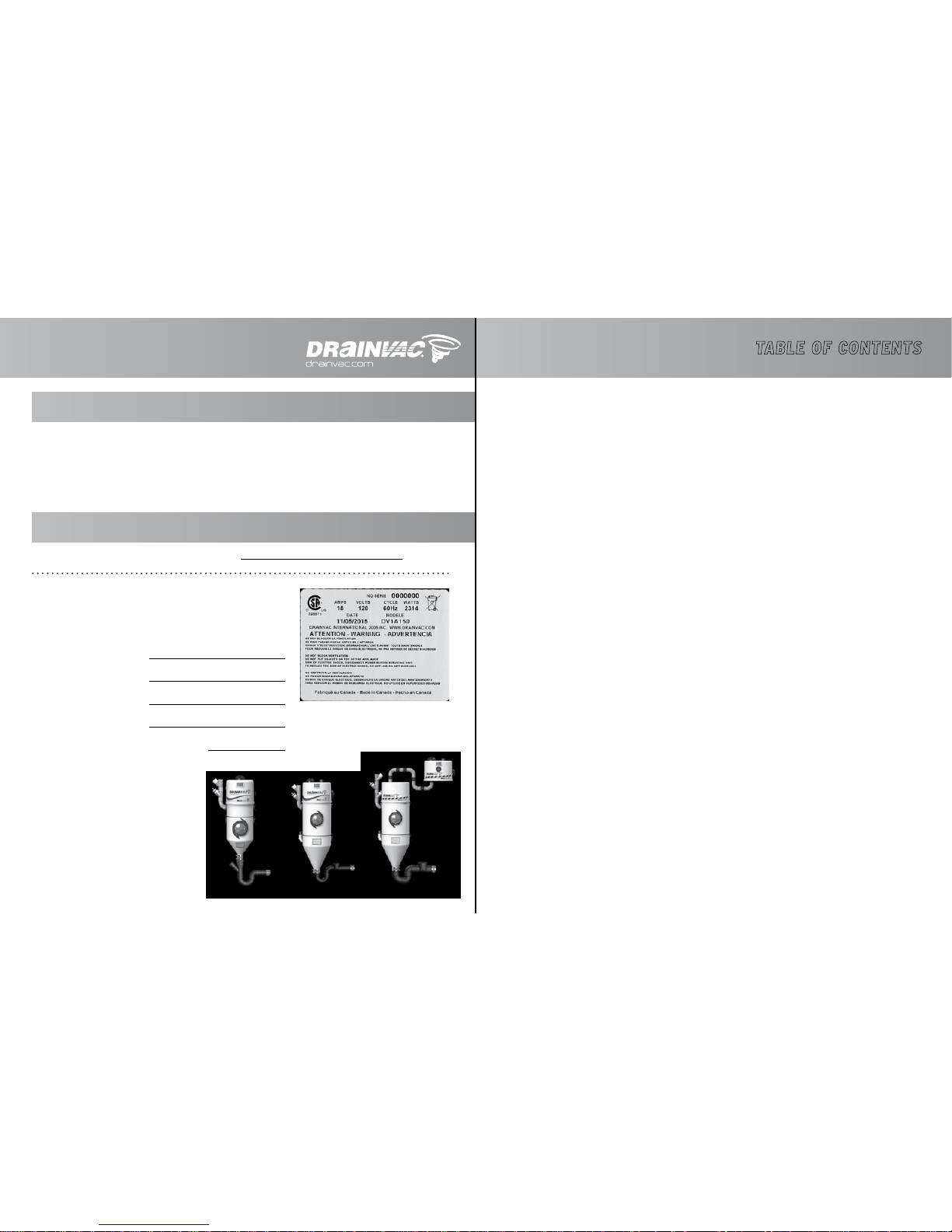
Model* :
Serial number * :
Retailer’s name :
Date of purchase :
Date of the last maintenance :
*These informations are found on a metal
tag located on the left side of the unit.
Metal tag
Page 4
76
TiTreTiTre HOW THE SySTEM WORkSHOW THE SySTEM WORkS
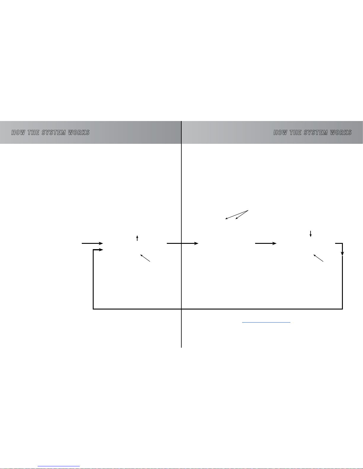
Drainvac central vacuum cleaners are designed to vacuum both solids and liquids. The tank never has to be
emptied manually since the systems are directly connected to the building’s drainpipe through which the
wastewater is automatically evacuated.
Step 1
Unit is off.
Step 2
Start up: The dirt begins to be
vacuumed and water flows in.
The water comes
into contact with
the electrodes
The rubber
hand opens
The rubber hand
is closed
Step 3
Water flows in, reaching the level of
the electrodes (approx. 10 minutes).
Step 4
The wastewater is evacuated to
the sewer (approx. 20 seconds).
To see a video of the sequence, go to
http://youtu.be/KdPL3ysamgY
OPERATION SEQUENCE
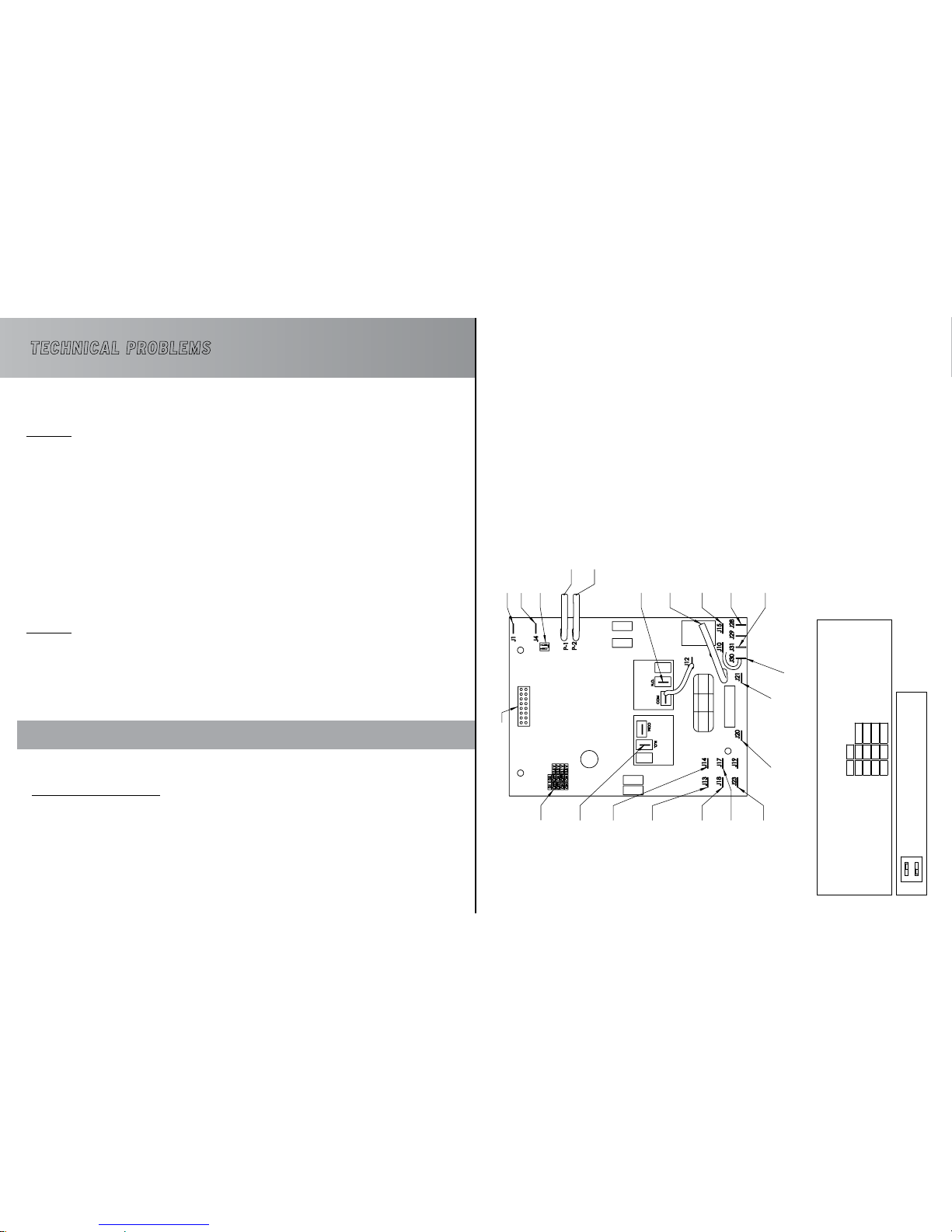
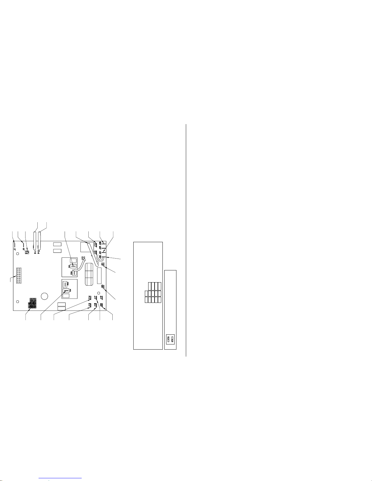
The sensitivity of the electrodes can be modified by the printed circuit board. See Annex for more information.
Page 5
98
TiTreTiTre bOOSTER HEAD OPTION TyPE Of UNITS
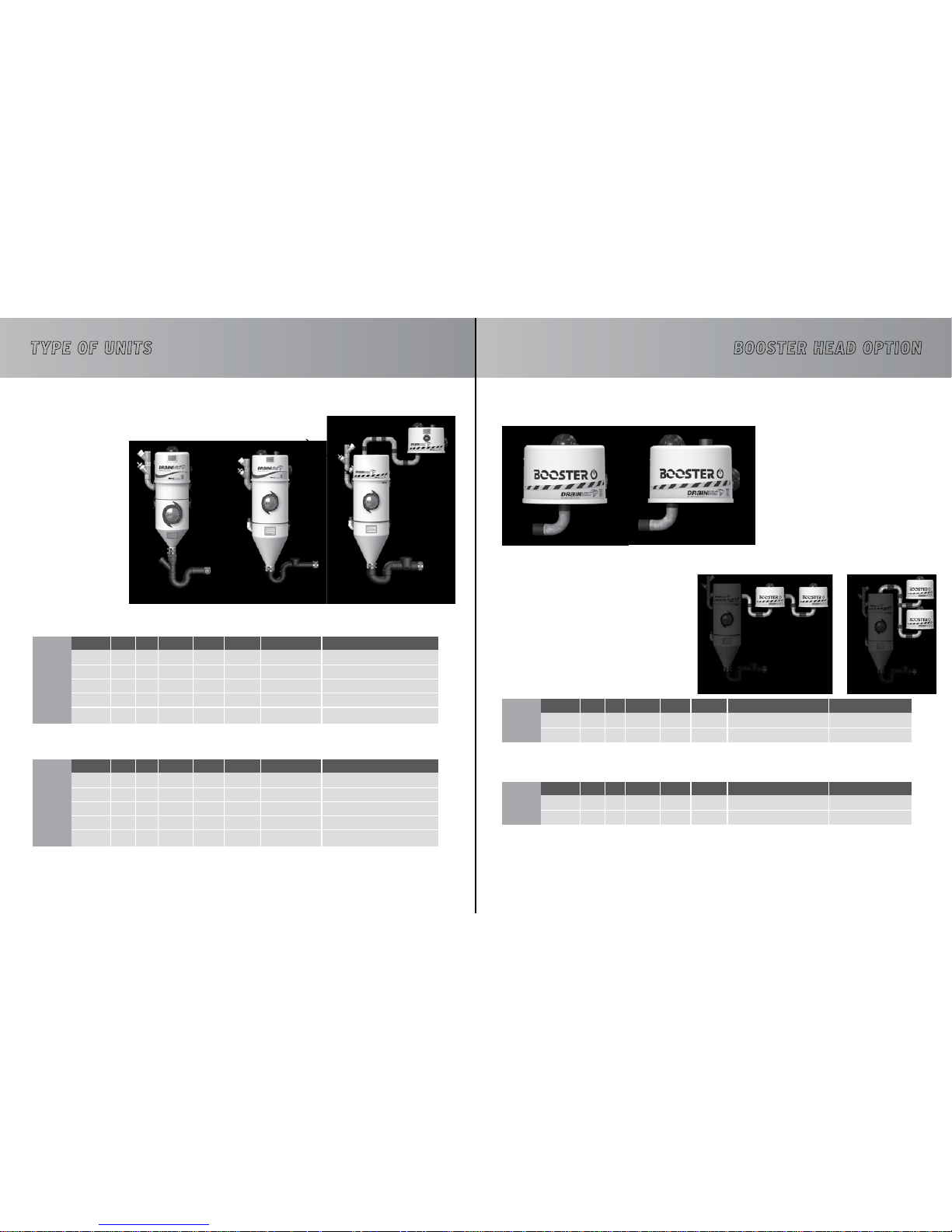
You have purchased one of the following models. Identify the one related to it.
The model number appears on the technical label on the left side of your unit.
Refer to pages 12 to 17 for a detailed illustration of your model.
TECHNICAL SPECIFICATIONS
NORTH AMERICA (120V)
INTERNATIONAL (240V)
MODELS
MODELS
MODELS
MODELS
DV1A150
DV2A310
DV2A31
DV2A32
DVDC40
TETE01
TETE06
TETE02
TETE05
DF1A150
DF2A310
DF2A31
DF2A32
DFDC40
AIRWATTS
AIRWATTS
AIRWATTS
AIRWATTS
700
2 x 355
2 x 355
4 x 355
2 x 395
395
2 x 355
DVDC40
DV2A31
395
2 x 355
DFDC40
DF2A31
700
2 x 355
2 x 355
4 x 355
2 x 395
H
2
O
H
2
O
mm
H2O
mm
H2O
130
160
160
160
180
110
160
2921
4064
3300
4064
4064
4064
4609
CFM
CFM
m
3
/h
m
3
/h
150
106
106
200
115
110
106
194
195
290
195
195
340
194
DECIBELS
DECIBELS
DECIBELS
DECIBELS
66
68
68
78
72
75
78
75
78
66
68
68
78
72
MOTOR
MOTOR
MOTOR
MOTOR
1
2
2
4
2
1
2 (
in series)
1
2 (
in series)
1
2
2
4
2
AMPS
AMPS
AMPS
AMPS
14
18
18
2 x 18
2 x 13
13
18
7,5
11
8
10,8
10,8
2 x 10,8
2 x 7,5
CAPACITY (gal./l)
CAPACITY (gal./l)
4 gal / 18 L
6 gal / 29 L
6 gal / 29 L
6 gal / 29 L
6 gal / 29 L
4 gal / 18 L
6 gal / 29 L
6 gal / 29 L
6 gal / 29 L
6 gal / 29 L
DIMENSIONS (in/cm)
DIMENSIONS (in/cm)
FOR MODELS...
FOR MODELS...
DIMENSIONS (in/cm)
DIMENSIONS (in/cm)
12”dia.x 37” / 30cm dia.x 93cm
15”dia.x 49” / 38cmdia. x122.5cm
15”dia.x 49”
/
38cmdia. x122.5cm
15”dia.x 49”
/
38cmdia. x122.5cm
15”dia.x 49”
/
38cmdia. x122.5cm
15”dia.x 12” / 38cmdia. x30cm
15”dia.x 12” / 38cmdia. x30cm
15”dia.x 12” / 38cmdia. x30cm
15”dia.x 12” / 38cmdia. x30cm
12”dia.x 37” / 30cm dia.x 93cm
15”dia.x 49” / 38cmdia. x122.5cm
15”dia.x 49”
/
38cmdia. x122.5cm
15”dia.x 49”
/
38cmdia. x122.5cm
15”dia.x 49”
/
38cmdia. x122.5cm
Booster heads are also available on certain models to add extra power to your unit.
If your Automatik system is equipped with an auxiliary 24V outlet, you can
add one or several booster heads at any time.
Contact your retailer or distributor for more information.
TECHNICAL SPECIFICATIONS
NORTH AMERICA (120V)
INTERNATIONAL (240V)
Technical label
1 motor 2 motors
Page 6
1110
TiTreTiTreLOWER TANk OPTION
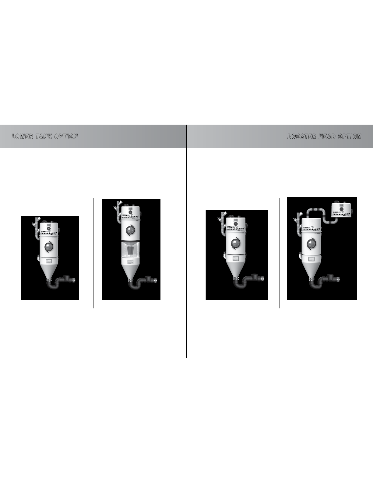
Take note that a standard tank system can be replaced by a lower tank system at all times and on all
models. Contact your retailer or your distributor for more information.
Please note that the illustrated models in this manual will be the standard tank model by default to simplify
the illustrations.
Standard Tank Lower Tank
LOWER TANK ADVANTAGES
• Facilitates maintenance.
• To remove oversized materials or an accumulation of hair, paper, etc.
• Strongly suggested when the unit is used by many people (commercial applications).
The lower tank option is always recommended when enough space is available.
bOOSTER HEAD OPTION
Standard head Booster head
BOOSTER HEAD ADVANTAGES
• Fo r additional power to your unit.
• When space is limited, the booster head can be installed on the side.
Please note that the illustrated models in this manual will be the standard head model by default to
simplify the illustrations.
Page 7
1312
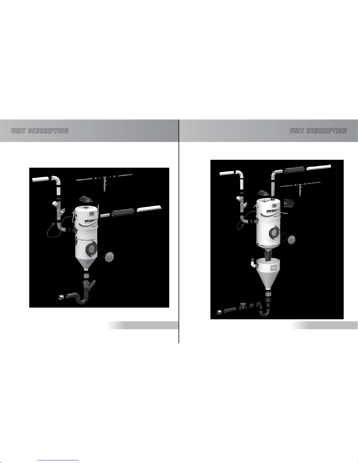
TiTreTiTreUNIT DESCRIPTION
DV1A150 / DF1A150
Vacuum pipe
Audioprotek
muffler
Audioprotek
muffler
24V plug
Cold water supply
2 motor unit
Porthole
O-ring
Porthole window
Outdoor vent
Dust entry
Rubber hand
Power cord
Water discharge (Dia: 2in / 5cm)
UNIT DESCRIPTION
DV2A310 / DF2A310
Vacuum pipe
Audioprotek
muffler
24V plug
Cold water supply
One motor unit
Porthole
O-ring
Porthole window
Outdoor vent
Dust entry
Water discharge
(Dia: 2in / 5cm)
Power cord
Page 8
1514
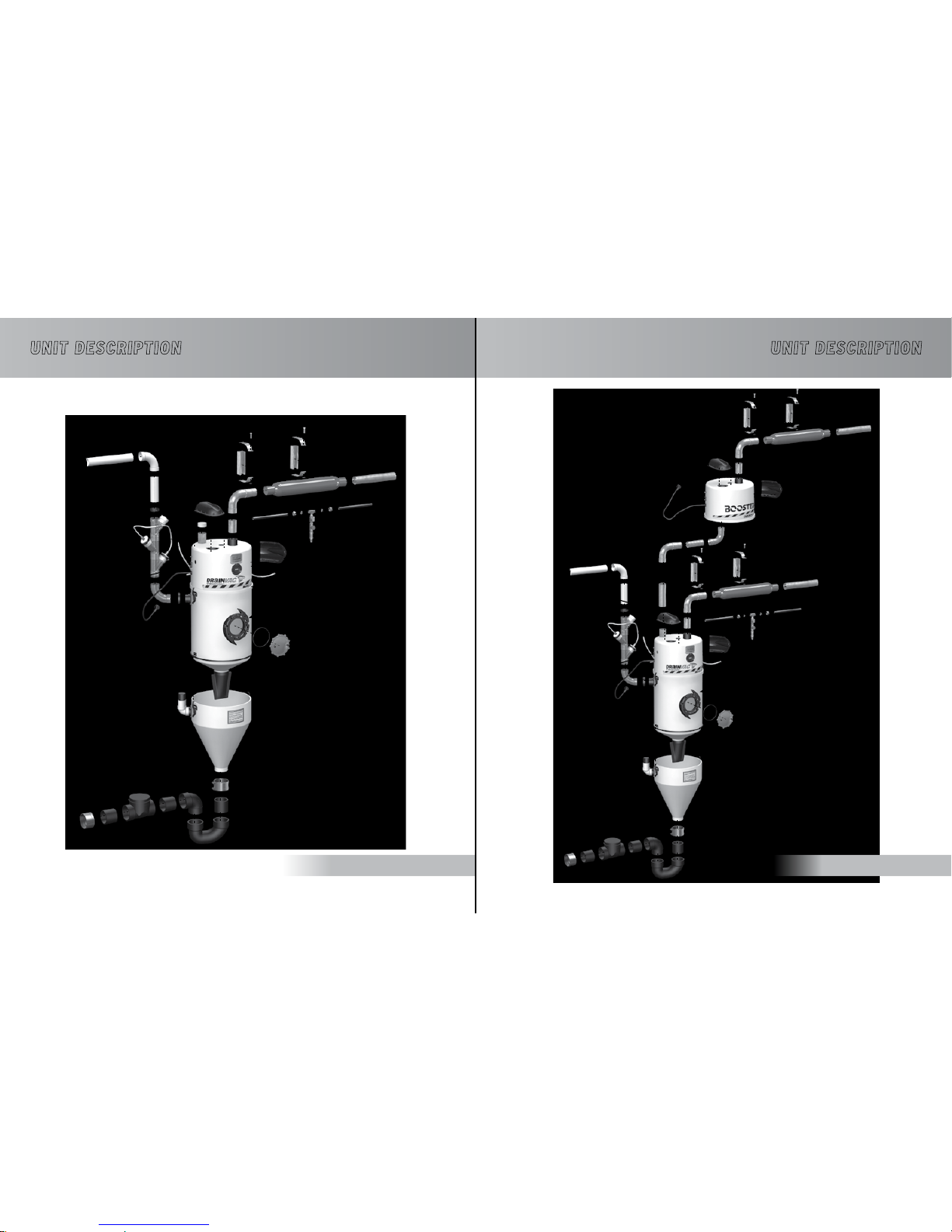
TiTreTiTreUNIT DESCRIPTION
DV2A31 / DF2A31
Vacuum pipe
Audioprotek
muffler
2 motor booster head
24V plug
Cold water supply
2 motor unit
Porthole
O-ring
Audioprotek muffler
Porthole window
Outdoor vent
Outdoor vent
Dust entry
Rubber hand
Power cord
Audioprotek muffler
Audioprotek muffler
Power cord
24V plug
Water discharge (Dia: 3in / 7.6cm)
UNIT DESCRIPTION
DV2A32 / DF2A32
Vacuum pipe
Audioprotek
muffler
24V plug
Cold water supply
2 motor unit
Porthole
O-ring
Porthole window
Outdoor vent
Dust entry
Rubber hand
Power cord
Audioprotek muffler
Water discharge (Dia: 3in / 7.6cm)
Page 9
1716
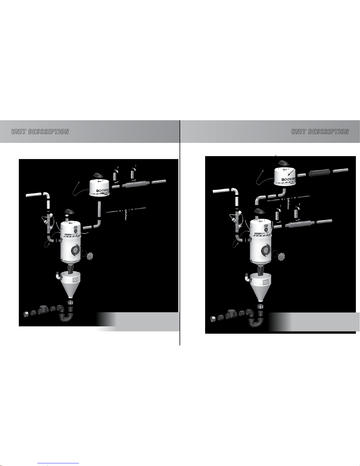
TiTreTiTreUNIT DESCRIPTION
DVDC40 / DFDC40
SERIES CONFIGURATION
FOR OPTIMUM SUCTION POWER
Vacuum pipe
Audioprotek
muffler
24V plug
One motor booster head
24V plug
Cold water supply
One motor unit
Porthole
O-ring
Porthole window
Outdoor vent
To outside vent
Dust entry
Rubber hand
Power cord
Audioprotek muffler
Power cord
The DVDC40 and DFDC40 can be mounted in two
different configurations.
This one is recommended for optimum air flow.
Suction Power : 120 H2O / 2832 mmH2O
Air Flow : 200 CFM / 340 m3/h
Water discharge (Dia: 3in / 7.6cm)
UNIT DESCRIPTION
DVDC40 / DFDC40
PARALLEL CONFIGURATION
FOR OPTIMUM AIR FLOW
Vacuum pipe
Audioprotek
muffler
24V plug
One motor booster head
24V plug
Cold water supply
One motor unit
Porthole
O-ring
Porthole window
Outdoor vent
Dust entry
Power cord
Audioprotek muffler
Power cord
The DVDC40 and DFDC40 can be mounted in two
different configurations.
This one is recommended for optimum suction power.
Suction Power : 180 H2O / 4609 mmH2O
Air Flow : 115 CFM / 194 m3/h
Water discharge (Dia: 3in / 7.6cm)
Rubber hand
Page 10
1918
+
=
TiTreTiTre
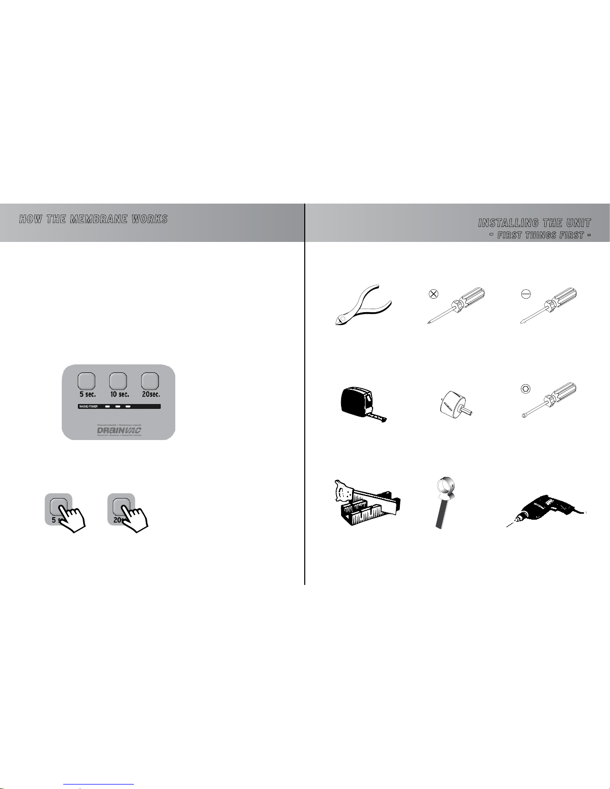
HOW THE MEMbRANE WORkS
Cutting Pliers
Measuring Tape
Phillips Screwdriver
Hole Saw
2.25” (57 mm)
Drill
0.5” (12.5 mm) bit
Mitre-Box and Saw PVC Pipe Cutter
2” (50 mm)
Regular Screwdriver
Socket Head Screwdriver
(for the clamps)
(supplied with the unit)
THE TOOLS YOU WILL NEED
or
INSTALLING THE UNIT
-
fIRST THINGS fIRST -
As illustrated on pages 6 and 7 of this manual, the Automatik system evacuates its wastewater automatically
after approximately 10 minutes. The membrane allows you to adjust the time lapse during which the unit will
deactivate before restarting its cycle; the default time lapse is 20 seconds.
Setting the timing can only be done when the unit is in use (not while it is evacuating the wastewater).
Evacuation Time
Minimum: 5 seconds
Maximum: 35 seconds
WHY CHANGE THIS PARAMETER?
• With a lower tank model, the unit can reactivate as soon as there is no wastewater left to flow through
the rubber hand (in other words when all the wastewater is in the lower tank).
• If the unit’s drain is located very close to the pipe leading to the sewer and that there is less restriction
to the amount of wastewater that can be evacuated, the evacuation time could only take 15 seconds.
• On the other hand, if the diameter of the pipe leading to the sewer is smaller and restrains the amount
of water that can be evacuated, increasing the evacuation time to over 20 seconds could be necessary.
SETTING THE EVACUATION TIMEFRAME
Press on one button only to set the time to 5, 10 or 20 seconds. Or consecutively press on two or three buttons to set the respective timing.
Example:
25 seconds of evacuation time
Page 11
2120
24” (60 cm)
10”
(25 cm)
53” (136 cm)
68” (174 cm)
[ DV1A150/DF1A150 = 49” (123 cm) ]
[ DV1A150/DF1A150 = 64” (162 cm) ]
[ 15” (38 cm) ]
*
24” (60 cm)
10”
(25 cm)
15” (38 cm)
TiTreTiTre
INSTALLING THE UNIT
- fIRST THINGS fIRST -
Cut the fastener
Gypsum Board
Wood Panel
Wall Stud
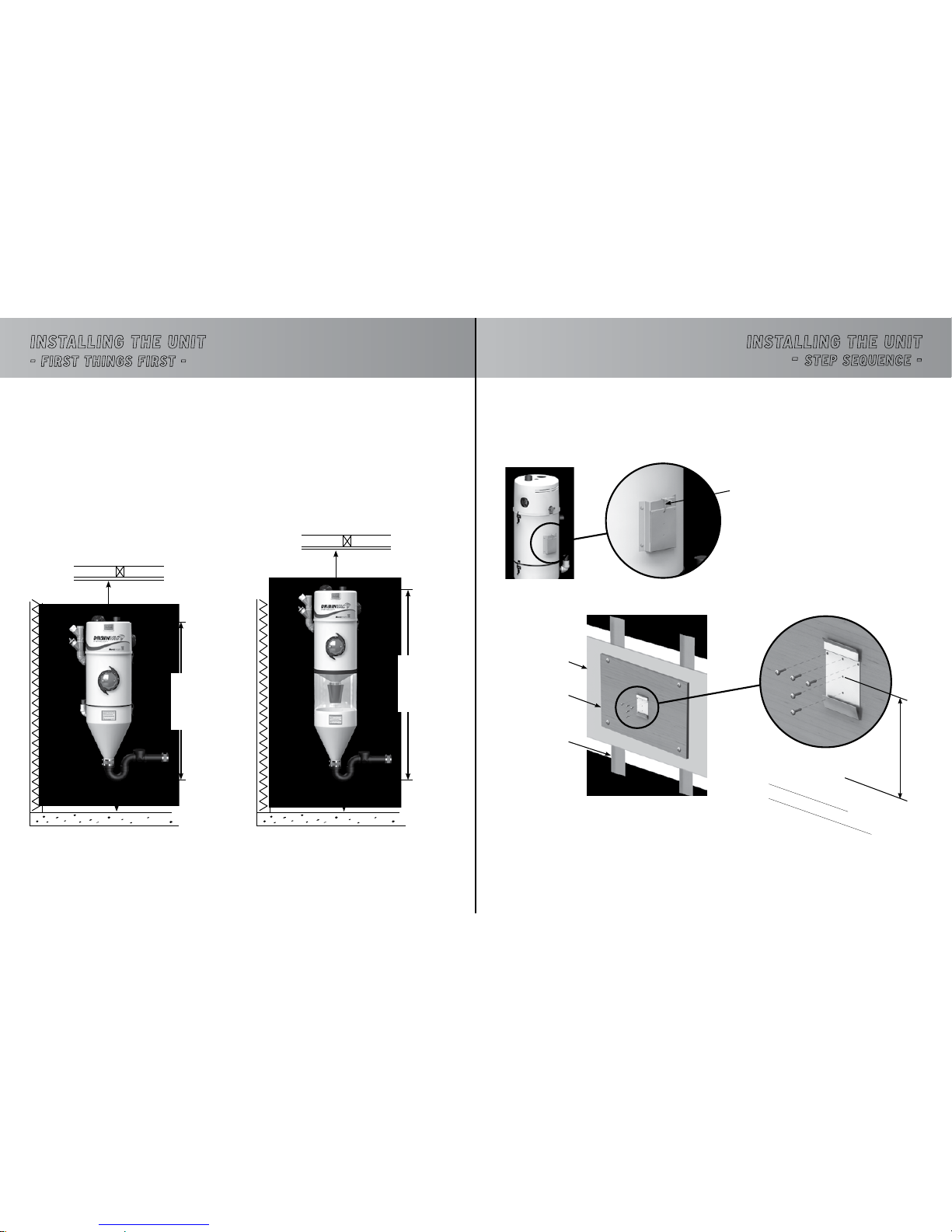
1) MOUNTING THE UNIT ON THE WALL
• Undo the fastener securing the wall bracket and base at the back of the unit with cutting pliers.
• Attach the bracket to the wall with the five screws supplied with the unit.
If the wall includes wall studs covered with gypsum
board, we recommend installing a wooden panel
screwed to the wall studs beforehand for more
stability.
Suggested distance from the floor
Standard installation: 50” (125 cm)
Installation with lower tank
Tank : 40” (100 cm)
Unit : 65” (165 cm)
INSTALLING THE UNIT
-
STEP SEQUENCE -
WHERE WILL YOU INSTALL THE UNIT?
We recommend installing the system on the lowest level of the building to avoid having to work against
gravity. The basement is generally the most ideal location, near the building’s main drainpipe. A cold water
pipe must also be available and connected to the unit. Vents are necessary if the unit is further then 6’
(2m) away from the main drain. If there is no basement, the garage or a storage room will do.
MINIMUM DIMENSIONS AND SPACING
It is important to install the unit in a location where it will be easily accessible for maintenance and to effectively evacuate the waste. The following is the minimum spacing recommended:
* For models with a standard tank, the bottom of the P-Trap can be installed at 15” (38cm) from the floor.
However, we recommend 26” (66 cm), if possible, so that a pail can be placed under the unit, if need be,
when removing the P-Trap.
Page 12
2322
TiTreTiTre
INSTALLING THE UNIT
-
STEP SEQUENCE -
Clamp
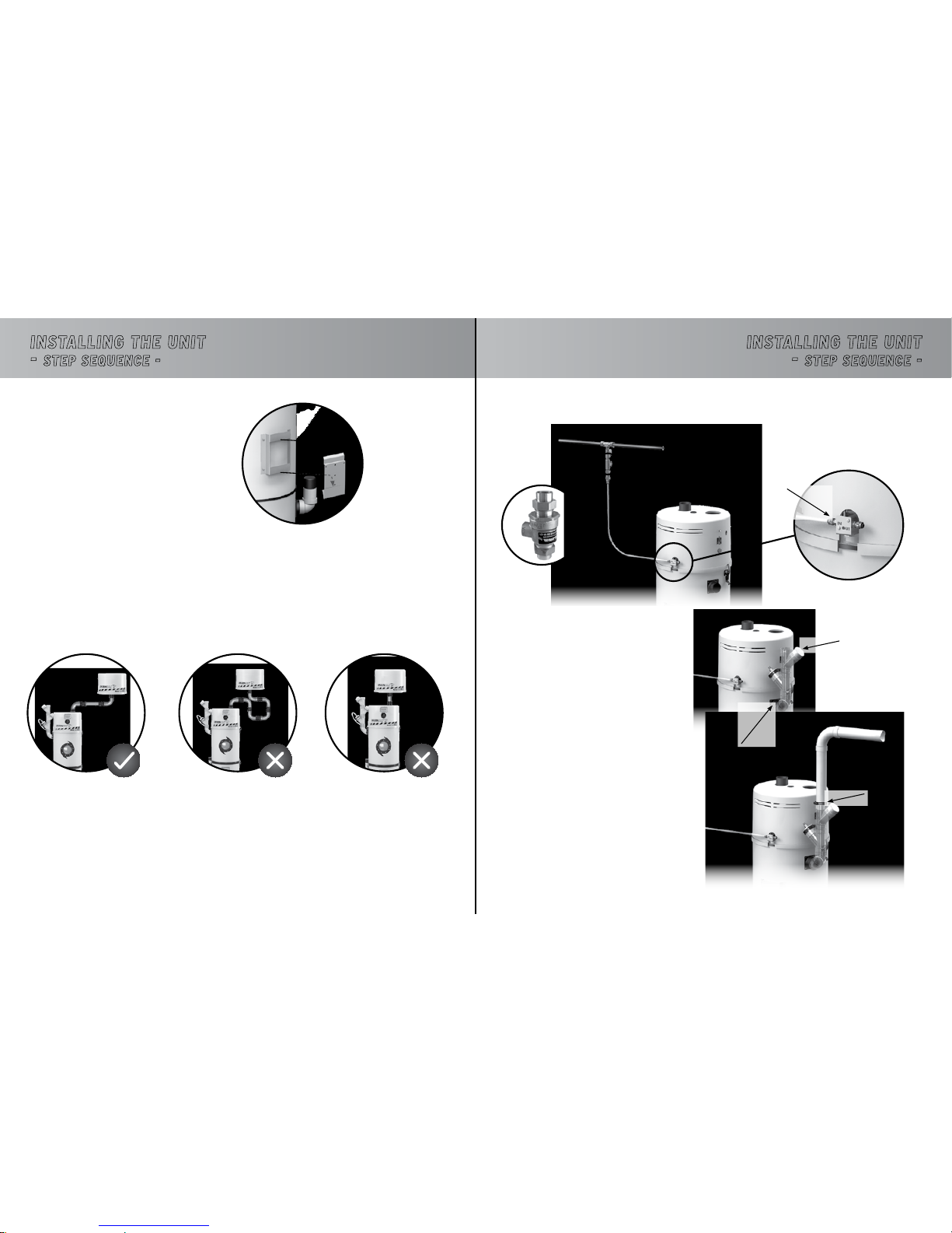
2) CONNECT THE DUST AND WATER INLETS
• Connect the building’s cold water supply to the unit’s water inlet.
Clamp
Practical plug for
maintenance
(When needed, use a
brush to clean the
inside of the tubes)
INSTALLING THE UNIT
-
STEP SEQUENCE -
• Lift the unit and slide its support onto the
wall bracket.
• If your unit is equipped with a lower tank, repeat the same steps to attach it to the wall.
• If your unit is equipped with one or several booster heads, repeat the same steps to attach it, or
them, to the wall.
Optimum efficiency Not recommended
Each booster head can be installed according to the available space without compromising the height of the
head in relation to the unit.
However, we recommend that you keep the number of joints (elbows) to a minimum to optimize air circulation
and performance.
POSITIONING A BOOSTER HEAD
POSITIONING THE LOWER TANK
Not recommended
•A backflow preventer may be
required in some municipalities.
It is installed at the water input of
the unit and prevents a backflow
of the unit in the main pipeline of
the residence.
• Connect the dust inlet
(transparent tubes) to the unit
securing it with a clamp.
* N.B. The tubes have been preassembled by pressure. Do not
use glue.
• Connect the suction hose to the
unit’s dust inlet, securing it with
a clamp.
Backflow preventer
(Optional, sold seperatly)
Quick connect
(Push-in the nozzle to
insert the cable and
release to lock-in)
Page 13
2524
TiTreTiTre
INSTALLING THE UNIT
-
STEP SEQUENCE -
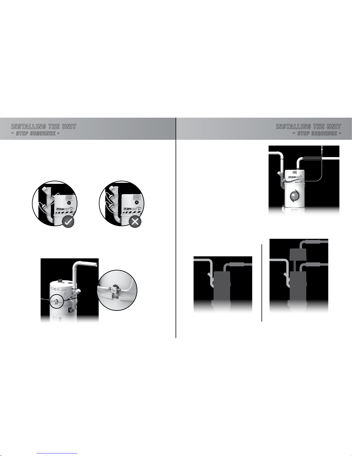
Dust Inlet Dust Inlet
Air Outlet
Air Outlet #1
Air Outlet #2
AIR OUTLET WITH A BOOSTER HEAD
Important: If your unit includes one or several booster heads, each one must be equipped with an
independent air outlet.
Model with no Booster Head Model with a Booster Head
4) CONNECT THE AIR OUTLET
• Connect the air outlet to the unit, securing it with
a clamp (do not glue). An air outlet leading outside
the building is mandatory for all Automatik
systems.
If your model includes 2 motors, the air outlet is on top
of the unit. If it only includes 1 motor, the air outlet is
on the side of the unit.
Air Outlet
INSTALLING THE UNIT
-
STEP SEQUENCE -
Some units are equipped with two water injectors. In this case, it is important that they be positioned facing
each other so that the water covers a greater surface.
POSITIONING THE WATER INJECTORS ON
THE DUST INLET
• Connect the unit’s water outlet to the water hoses linked to the water injectors.
3) CONNECT THE WATER OUTLET
Page 14
2726
TiTreTiTre
INSTALLING THE UNIT
-
STEP SEQUENCE -
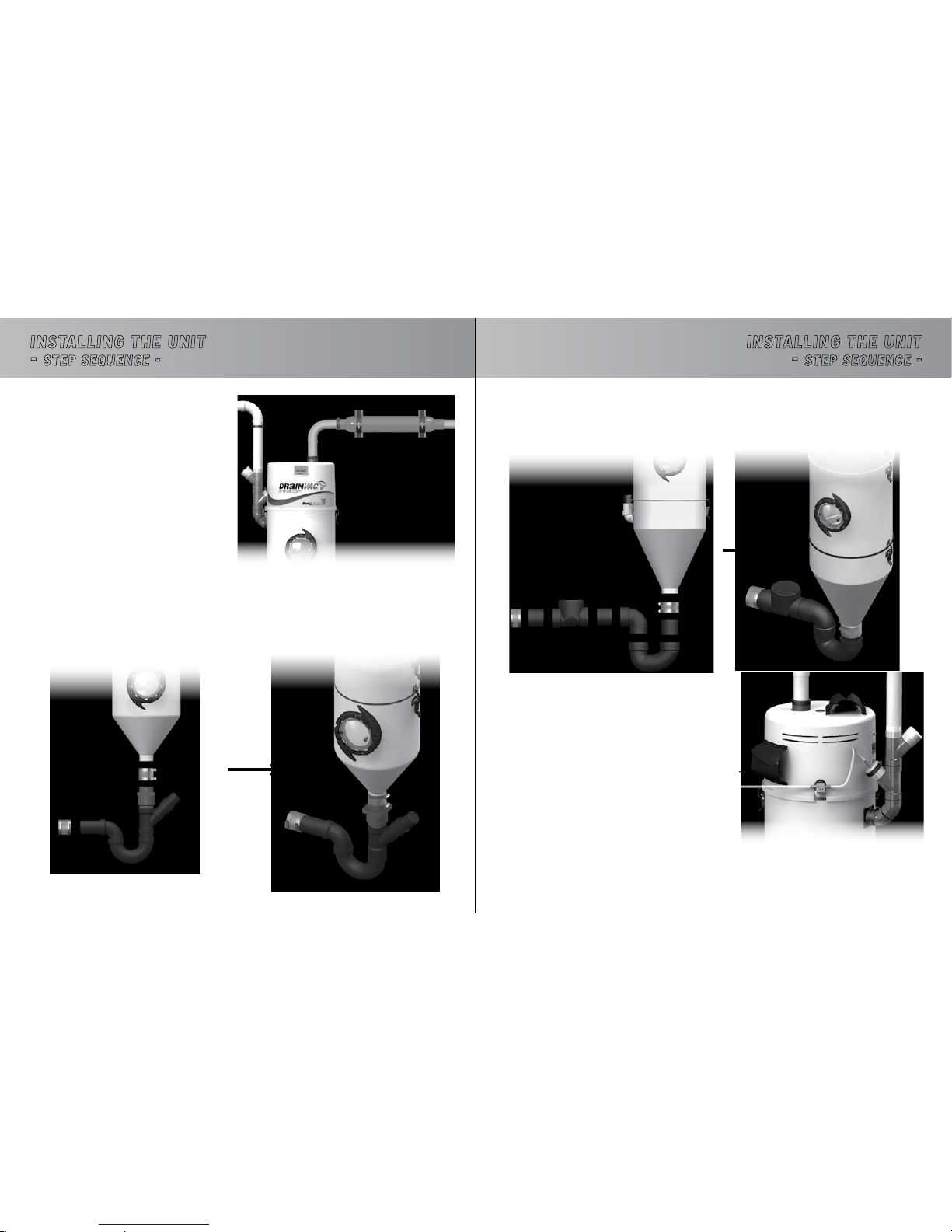
ALL MODELS (OTHER THAN DV1A150 AND DF1A150)
• Connect the components of the wastewater piping system as illustrated, securing the system with the
clamps supplied with your unit.
Back View of the Unit
(Model DV2A310)
6) ADD THE AUDIOPROTEK
MUFFLERS
• Instructions on how to assemble the Audioprotek
mufflers are included in a leaflet inside the packaging.
* N.B. All models equipped with only one motor
include only one muffler centered on the top of
the unit.
INSTALLING THE UNIT
-
STEP SEQUENCE -
Steel Muffler
STEEL MUFFLER
MODELS DV1A150 AND DF1A150
• Some units are equipped with a (red) steel
muffler to absorb the noise produced by more
powerful systems.
Contrary to plastic mufflers, this steel muffler
must be installed on the wall. Installation
instructions are provided with the leaflet
provided with the muffler.
• Connect the components of the wastewater piping system as illustrated, securing the system with the
clamps supplied with your unit.
5) CONNECT THE WASTEWATER PIPE
Page 15
2928
Figure C Figure D Figure E
Figure A Figure B
TiTreTiTreINSTALLING THE PIPING SySTEM
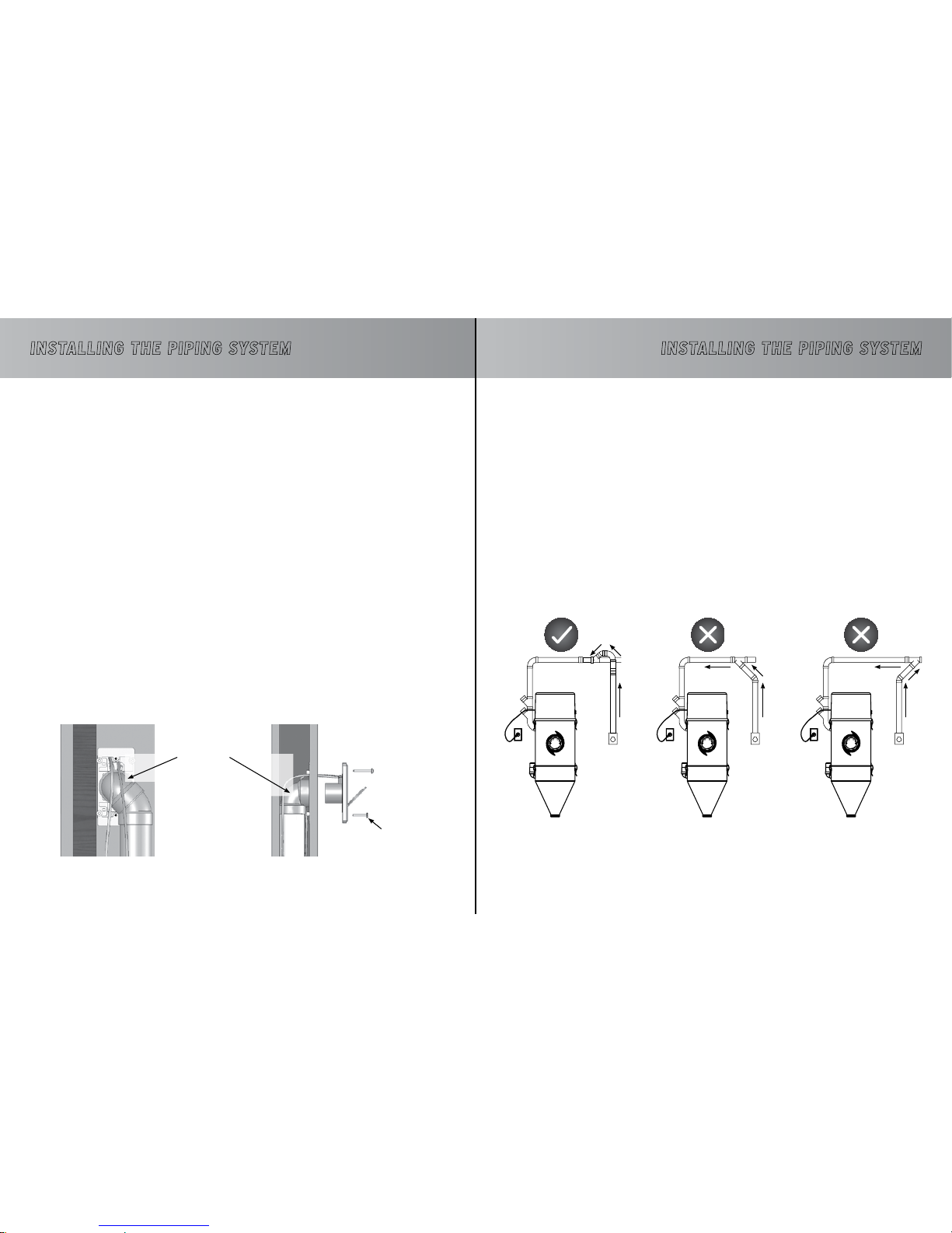
FROM DRY TO WET
If you wish to replace your conventional (dry) vacuum to an Automatik system, please follow the instructions below.
1. The Automatik system must be installed near the sanitary sewer. If your previous unit was placed to one
end of the building, but the sewer is to the other end, the unit must be reinstalled at a closer range of the
main drain and the pipeline must change its direction as well (Figure E). This will prevent unwanted dust
to cling onto the pipe which will eventually clog the duct.
2. The pipes leading upwards must be slightly higher then the main pipeline to prevent liquids from flowing
back down (Figure C).
3. If short elbows was used to mount the pipeline, these must be taken off. The minumum cornering pipe
must be at least a medium elbow, but an 45
o
pipe is recommended for all corners for an optimal efficiency.
4. The inclination of the main pipeline must tilt a little more then using an ordinary vacuum to facilitate the
flow of the liquids.
INSTALLING THE PIPING SySTEM
The following pages illustrate piping diagrams, typical installations and the parts that we recommend
for the optimum performance of your central vacuum system.
GENERAL INFORMATION
• An air outlet leading to outside must always be installed on your unit. Make sure that the evacuated
air does not lead under a carport.
• If your unit includes two motors, it is important to use metal piping and couplings for the air outlet.
• To determine where to locate the wall inlets, use the length of the vacuum hose as a basis, measuring
the furthest point from the wall where the wall inlets are to be installed. Do the same for all the wall
inlets until all areas of the house or building can be reached with the vacuum hose, by moving it from
one wall inlet to another; don’t forget to install one in the garage or outside to vacuum your car.
• If your walls are made of gypsum board, never install a wall inlet in the center of the wall. Drill the
holes for the wall inlets close to a wall stud or a door frame.
• Any screw length can be used if you install the piping as illustrated in Figure A.
• If you install the piping as illustrated in Figure B, make sure to position the small screw in the right place
to avoid that a longer screw goes through the piping.
• Always use a short elbow when connecting the wall inlets (Figures A and B) to prevent long objects (for
example, a pencil) that may have been vacuumed by mistake from blocking the piping further on.
Small screw
Short elbow
Page 16
3130
TiTreTiTreINSTALLING THE PIPING SySTEM
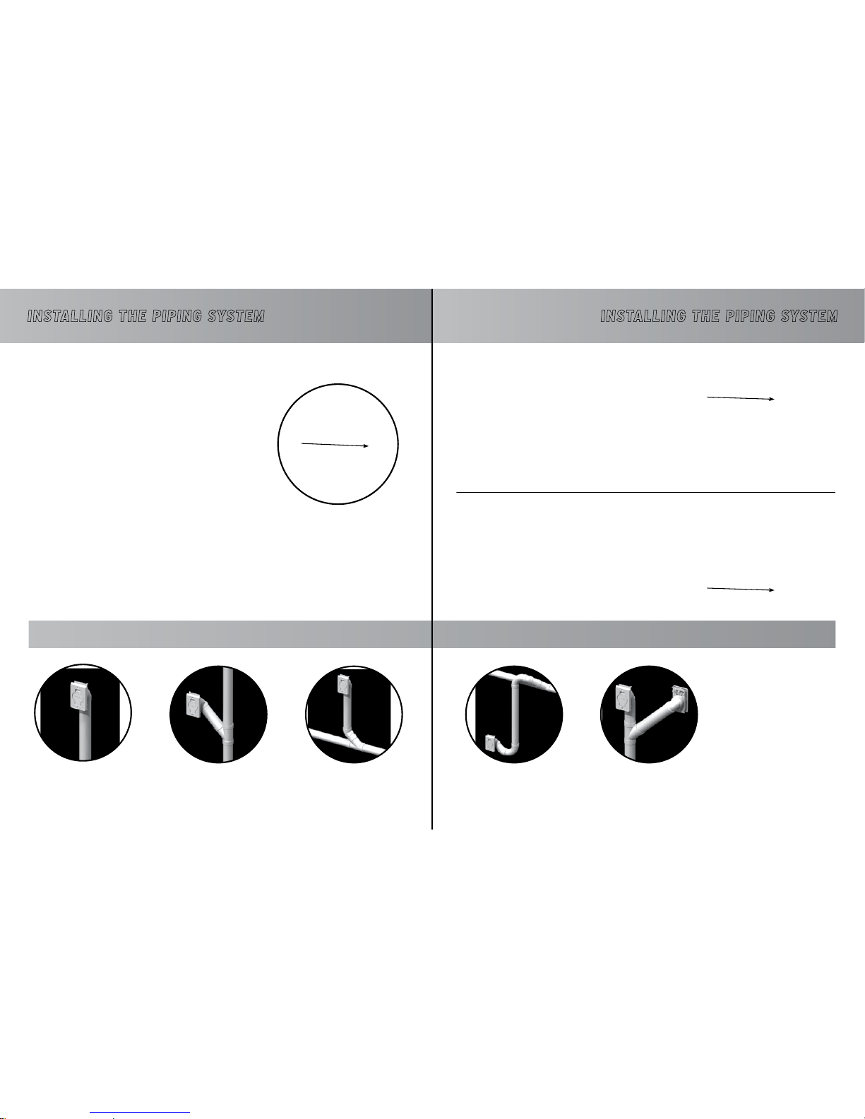
DIAGRAM OF A RESIDENTIAL INSTALLATION
DIFFERENT INSTALLATION POSSIBILITIES
On the top floor
(at the end of a pipeline)
On the first floor
(connected above a pipeline
under the floor)
On an intermediary floor
Always have a slight inclina-
tion of the piping towards
the unit.
Inclination
INSTALLING THE PIPING SySTEM
DIAGRAM OF A COMMERCIAL INSTALLATION
In the basement
(connected under a pipeline
under the floor)
Back to back
Always have a slight inclination of the piping towards the unit.
Under the floor
Through the ceiling
Installation example in series
Inclination
Inclination
Page 17
3332
TiTreTiTreINSTALLING THE PIPING SySTEM
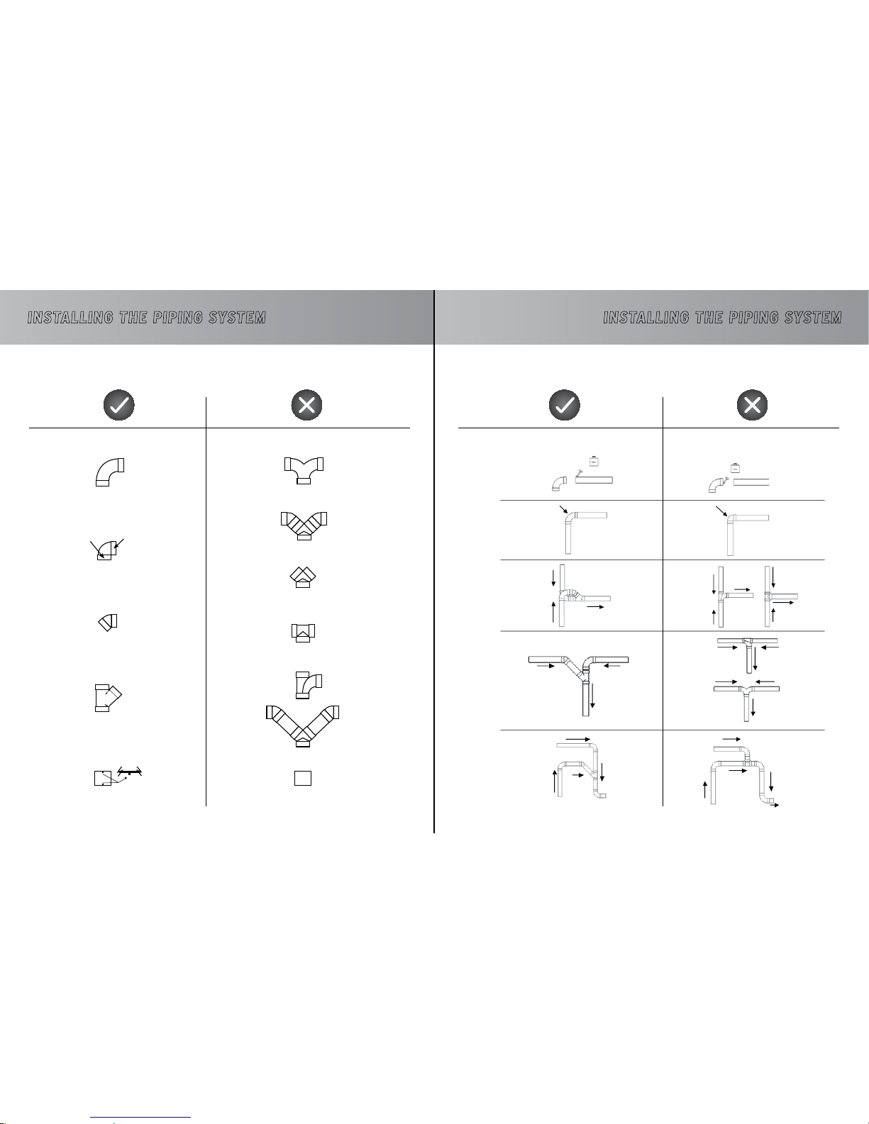
EXAMPLES OF PROPER AND IMPROPER INSTALLATIONS
Joint with inside stoppers
Thick wallThin wall
For wall plates only
Smooth joint without inside stoppers
INSTALLING THE PIPING SySTEM
EXAMPLES OF PROPER AND IMPROPER INSTALLATIONS
Page 18
3534
TiTreTiTreINSTALLING THE PIPING SySTEM
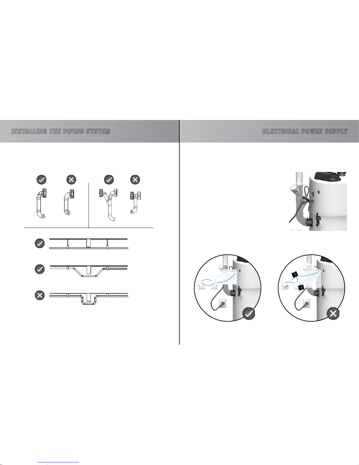
EXAMPLES OF PROPER AND IMPROPER INSTALLATIONS
ELECTRICAL POWER SUPPLy
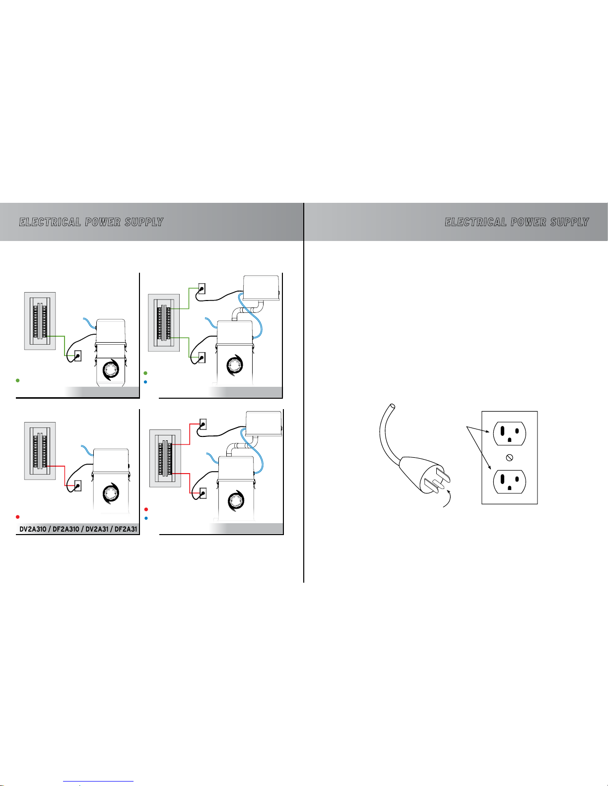
All the central vacuum system models in this manual are equipped with an electrical cord. An adequately powered electrical outlet must be installed near the unit. A dedicated electrical circuit must
be used for the unit and one for each booster head. Please
refer to page 32 for a detailed diagram of the
appropriate connections for your model.
• Install the 24-volt wires from the network (each
wall inlet) to the unit.
• If your unit includes one or several booster heads,
24-volt wires must be connected to each head
as illustrated on the following page (refer to the
diagram of your particular model).
• Connect the unit to the electrical outlet with the
power-supply cord.
• The vacuum cleaner is now ready to be used.
• After usage, circulate clear water to clean the ducts, then keep the unit running for 10 minutes to dry.
CONNECTION PROCEDURE
EXAMPLES OF PROPER AND IMPROPER INSTALLATIONS
24-volt wires
Page 19
3736
DV1A150 / DF1A150
DV2A310 / DF2A310 / DV2A31 / DF2A31
DV2A32 / DF2A32
DVDC40 / DFDC40
TiTreTiTreELECTRICAL POWER SUPPLy
DIAGRAMS OF THE APPROPRIATE CONNECTIONS FOR YOUR MODEL
DV1A150 : 15-amp. circuit / 120v
DF1A150 : 16-amp. circuit / 240v
DV2A310 & DV2A31 : 20-amp. circuit / 120v
DF2A310 & DF2A31 : 16-amp. circuit / 240v
Electrical Panel
Electrical Panel
DV2A32 : 20-amp. circuit / 120v
DF2A32 : 16-amp. circuit / 240v
24-volt wires (supplied with the unit)
Electrical Panel
DVDC40 : 15-amp. circuit / 120v
DFDC40 : 16-amp. circuit / 240v
24-volt wires (supplied with the unit)
Electrical Panel
If you experience voltage surge problems on your electrical circuit in spite of adequate connections,
a high magnetic circuit breaker can be installed on your electrical panel. Contact an electrician for
more information.
GROUNDING INSTRUCTIONS
These units must be grounded. If it should malfunction or breakdown, grounding provides a path of least
resistance for electric current to reduce the risk of electric shock. This appliance is equipped with a cord
having an equipment-grounding conductor and grounding plug. The plug must be inserted into an appropriate
outlet that is properly installed and grounded in accordance with all local codes and ordinances.
WARNIN G - Improper connection of the equipment-grounding conductor can result in a risk of electric shock. Check
with a qualified electrician or service person if you are in doubt as to whether the outlet is properly grounded.
DO NOT MODIFY THE PLUG PROVIDED WITH THE UNITS -
IF IT DOES NOT FIT THE OUTLET, HAVE A PROPER OUTLET INSTALLED
BY A QUALIFIED ELECTRICIAN.
These units are for use on a nominal 120V circuit and has a grounding attachment plug that looks like the one illus
-
trated below. Make sure that the electrical cord is connected to an outlet having the same configuration as the plug.
NO ADAPTOR SHOULD BE USED WITH THIS APPLIANCE.
*Illustration of a north-americain electrical outlet
Grounded
Outlet
Grounded pin
ELECTRICAL POWER SUPPLy
Page 20
3938
1
2
Figure F
TiTreTiTre
This unit complies with the WEEE (Waste Electrical and Electronic Equipment)
Guidelines, which promote the recycling of this type of waste equipment and en-
courage the development of products that are adapted to efficient waste reclamation at the end of their life cycle.
The WEEE Guidelines stipulate that the original supplier should agree to reclaim
any obsolete equipment free of charge. We recommend that you advise your supplier that you would like him to reclaim your unit when you order and replace it
with a new one.
Do not discard the unit with your regular garbage. The symbol representing a garbage bin on wheels on the
unit’s label (Figure C) attests to this requirement. You must ensure that, at the end of its life cycle, your unit
is reclaimed, treated and recycled by an authorized firm.
For more information, contact your municipal waste management department.
The acquirer of the Automatik system is commited to respect the environmental regula
-
tions of the liquid and solid waste disposal in the public water system.
MOTOR BRUSHES
Any mechanical system requires a minimum of maintenance and your system is no exception to the rule. We
therefore recommend that you inspect your motor brushes after 500 hours of use to check how worn they
are and replace them if need be.
On average, this inspection should occur:
• For residential applications: once every 3 to 5 years
• For commercial applications: once or twice a year
When the time comes, contact your retailer or distributor for this maintenance procedure.
WEEE GUIDELINES
MAINTENANCE PROCEDURES
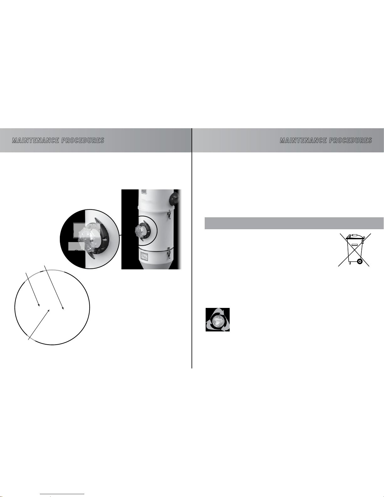
Use a scouring sponge to especially clean the protective
screen, the two electrodes and, if needed, the tank.
A blocked protective screen could reduce the unit’s
performance and dirty electrodes could not adequately
send a signal to the unit to pass on to the wastewater
evacuation cycle.
At the same time, it is recommended to visually inspect
the water inlet pipe and the rubber hand to make sure
that no foreign object is obstructing the
water flow.
REGULAR MAINTENANCE
Except for removing objects that could remain at the bottom of
your tank (for lower tank models), the only maintenance required is
cleaning the inside of the unit.
To proceed, you just have to
remove the porthole glass as
illustrated, by pivoting it in an
anti-clockwise motion using
the handles.
Protective
Screen
Water Inlet
Electrode
VISUAL INSPECTION
Your Automatik system is very user friendly and we recommend a visual inspection through the porthole
once a year or when needed. If you wish to clean the inside of the unit, refer to the following section
“Regular Maintenance”.
MAINTENANCE PROCEDURES
Page 21
40
COMMUTATEUR DIP / DIP-SWITCH
21
ON
CONNECTION MEMBRANE CABLE PLAT
MEMBRANE CONNECTION FLAT WIRE
NIVEAU DE SENSIBILITÉ
SENSITIVITY LEVEL
NIVEAU DE SENSIBILITÉ
SENSITIVITY LEVEL
ELECTRODE
ÉLECTRODE
ELECTRODE
ÉLECTRODE
#1
MOTEUR/MOTOR
L
#2
MOTEUR/MOTOR
N
#1
MOTEUR/MOTOR
N
NEUTRE ÉLECTROVANNE
SOLENOID VALVE NEUTRAL
*NEUTRE COMPTEUR HORRAIRE
*NEUTRAL TIMER
*NEUTRE TRANSFO
*NEUTRAL TRANSFO
NEUTRE BLANC
WHITE NEUTRAL
ALIMENTATION #1 SUPPLY
ALIMENTION FUSIBLE
120 VOLTS
FUSE LINE
PONT DE J30 À J10 (SEULEMENT POUR COMMERCIAL)
JUMPER J30 TO J10 (ONLY FOR COMMERCIAL)
*ALIMENTATION TRANSFO
*TRANSFO LINE
*ALIMENTATION COMPTEUR HORAIRE
*TIMER LINE
ALIMENTATION ÉLECTROVANNE
SOLENOID VALVE LINE
MISE À LA TERRE FIL VERT
GROUND GREEN WIRE
#2
MOTEUR / MOTOR
L
ON / OFF 24 VOLTS
ON / OFF 24 VOLTS
COMBINAISONS DE LA SENSIBILITÉ DES ELECTRODES
COMBINATIONS OF THE SENSITIVITY LEVEL OF ELECTRODES
D2
2.8V
2.1V
2.3V
2.5V
OFFONOFF
ONON
ON
OFF
OFF
D1
MEDIUM HIGH SE NSITIVITY
MEDIUM LOW SEN SITIVITY
LOW SENSITI VITY
HIGH SENSIT IVITY
SENSIBILIT É MOYENNE À HAUTE
SENSIBILIT É FAIBLE À MOYENNE
FAIBLE SENSIB ILITÉ
HAUTE SENSI BILITÉ
ANNEXE I
CIRC-14
DIAGRAMME DE CONNEXIONS
120 VOLTS
RESIDENTIEL : DV1A150, DV2A310
COMMERCIAL : DV2A31, DV2A32, DVDC40
ANNEX I
CIRC-14
CONNECTION DIAGRAM
120 VOLTS
RESIDENTIAL : DV1A150, DV2A310
COMMERCIAL : DV2A31, DV2A32, DVDC40
TiTre
THE UNIT WON’T START UP...
SOLUTION:
1) Check the circuit breaker in your electrical panel.
2) Check the unit’s circuit fuse/breaker.
3) Check the 24-volt circuit, as follows:
Try to establish electrical contact in a wall inlet with a metal object (for example, a coin).
--> If the unit starts up, the suction hose is defective.
--> If the unit doesn’t start up, check to see if the 24-volt wires are properly connected to the unit.
Try to establish an electrical contact between the two terminals of the 24-volt circuit on the unit with a
metal object (for example, a screwdriver).
--> If the unit starts up, a 24-volt wire is either cut or disconnected from one of the wall inlets.
--> If the unit won’t start up after these steps, the printed circuit is defective.
THE UNIT WON’T SHUT DOWN…
SOLUTION:
Check the 24-volt circuit as follows:
Disconnect one of the two wires on the unit’s 24-volt circuit.
--> If the unit shuts down, the problem could be that two 24-volt wires are touching themselves somewhere
or that the wall inlet is defective.
--> If the unit doesn’t shut down, the printed circuit is defective. Unplug the power cord.
SUPPORT
If you wish to speak with a customer service representative, please contact your supplier/dealer.
To find a retailer near you, please visit our website :
www.drainvac.com/retailers.html
Drainvac International
150 Brunet street, Mont-St-Hilaire, QC J3G 4S6, Canada
TECHNICAL PRObLEMS
Page 22
COMMUTATEUR DIP / DIP-SWITCH
21
ON
COMBINAISONS DE LA SENSIBILITÉ DES ELECTRODES
COMBINATIONS OF THE SENSITIVITY LEVEL OF ELECTRODES
D2
2.8V
2.1V
2.3V
2.5V
OFFONOFF
ONON
ON
OFF
OFF
D1
MEDIUM HIGH SE NSITIVITY
MEDIUM LOW SEN SITIVITY
LOW SENSITI VITY
HIGH SENSIT IVITY
SENSIBILIT É MOYENNE À HAUTE
SENSIBILIT É FAIBLE À MOYENNE
FAIBLE SENSIB ILITÉ
HAUTE SENSI BILITÉ
CONNECTION MEMBRANE CABLE PLAT
MEMBRANE CONNECTION FLAT WIRE
NIVEAU DE SENSIBILITÉ
SENSITIVITY LEVEL
NIVEAU DE SENSIBILITÉ
SENSITIVITY LEVEL
ELECTRODE
ÉLECTRODE
ELECTRODE
ÉLECTRODE
#1
MOTEUR/MOTOR
L
#2
MOTEUR/MOTOR
N
#1
MOTEUR/MOTOR
N
NEUTRE ÉLECTROVANNE
SOLENOID VALVE NEUTRAL
*NEUTRE COMPTEUR HORRAIRE
*NEUTRAL TIMER
*NEUTRE TRANSFO
*NEUTRAL TRANSFO
NEUTRE BLEU
BLUE NEUTRAL
ALIMENTATION #1 SUPPLY
ALIMENTION FUSIBLE
230 VOLTS
FUSE LINE
PONT DE J30 À J10 (SEULEMENT POUR COMMERCIAL)
JUMPER J30 TO J10 (ONLY FOR COMMERCIAL)
*ALIMENTATION TRANSFO
*TRANSFO LINE
*ALIMENTATION COMPTEUR HORAIRE
*TIMER LINE
ALIMENTATION ÉLECTROVANNE
SOLENOID VALVE LINE
MISE À LA TERRE FIL VERT
GROUND GREEN WIRE
#2
MOTEUR / MOTOR
L
ON / OFF 24 VOLTS
ON / OFF 24 VOLTS
ANNEXE II
CIRC-14
DIAGRAMME DE CONNEXIONS
23 0 VO LTS
RESIDENTIEL : DF1A150, DF2A31 0
COMMERCIAL : DF2A31, DF2A32, DFD C40
ANNEX II
CIRC-14
CONNECTION DIAGRAM
23 0 VO LTS
RESIDENTIAL : DF1A150, DF2A310
COMMERCIAL : DF2A31, DF2A32, DFD C40
Page 23
PRINTED IN CANADA (06-15)
 Loading...