

Page 1
Page 2
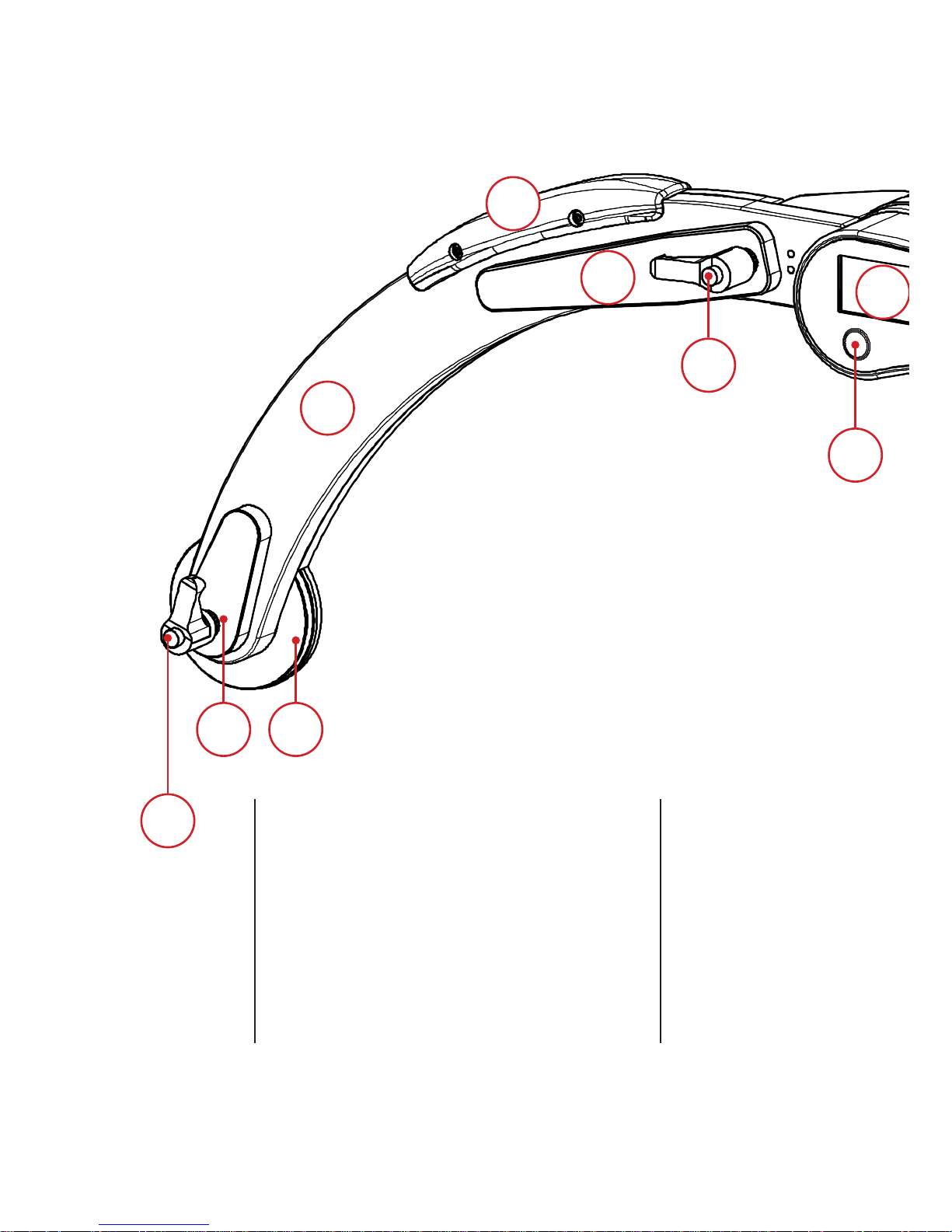
“ARCHIMEDE HR” PART LIST
1
7 4
10
11
9
13
14
15
16
8
1 Left arm in titanium
2 Right arm in titanium
3 Control Panel
4 Left support wheel
5 Right support wheel
6 Central support wheel
7 Lateral mechanical stop
8 Locking knob of central mechanical stop
9 Central mechanical stop
10 Locking knob of central mechanical stop
11 Left handle
12 Right handle
13 LCD Display
14 ON/OFF button
www.microplan-group.com
Page 3
18
19
5
2
12
6
3
7
20
21
15
16
17
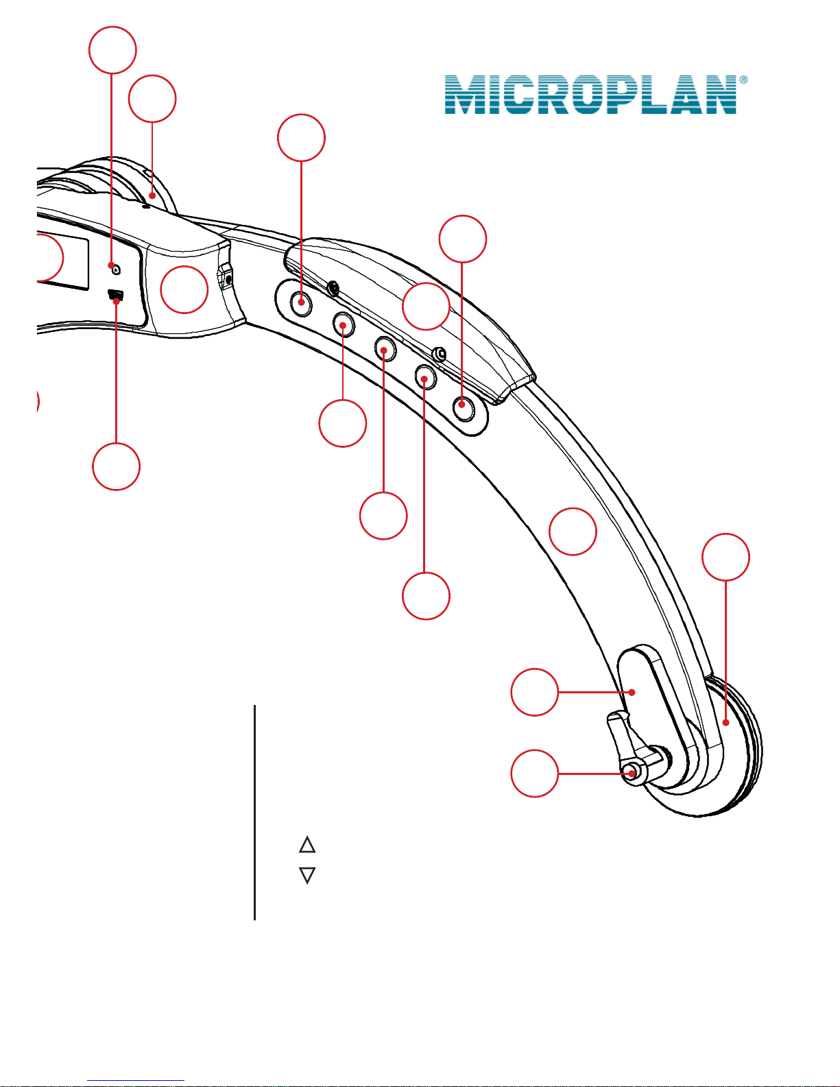
15 Bicolor led
16 Mini-USB input
17 “Save/Enter” button
18 MENU button
19
/ MINIMUM button
20
/ DISPLAY ROTATION
21 “Save/Enter” button
8
Page 4
2014©Microplan®
ARCHIMEDE_HR_en.indd
Versione: 14/11.20
ARCHIMEDE
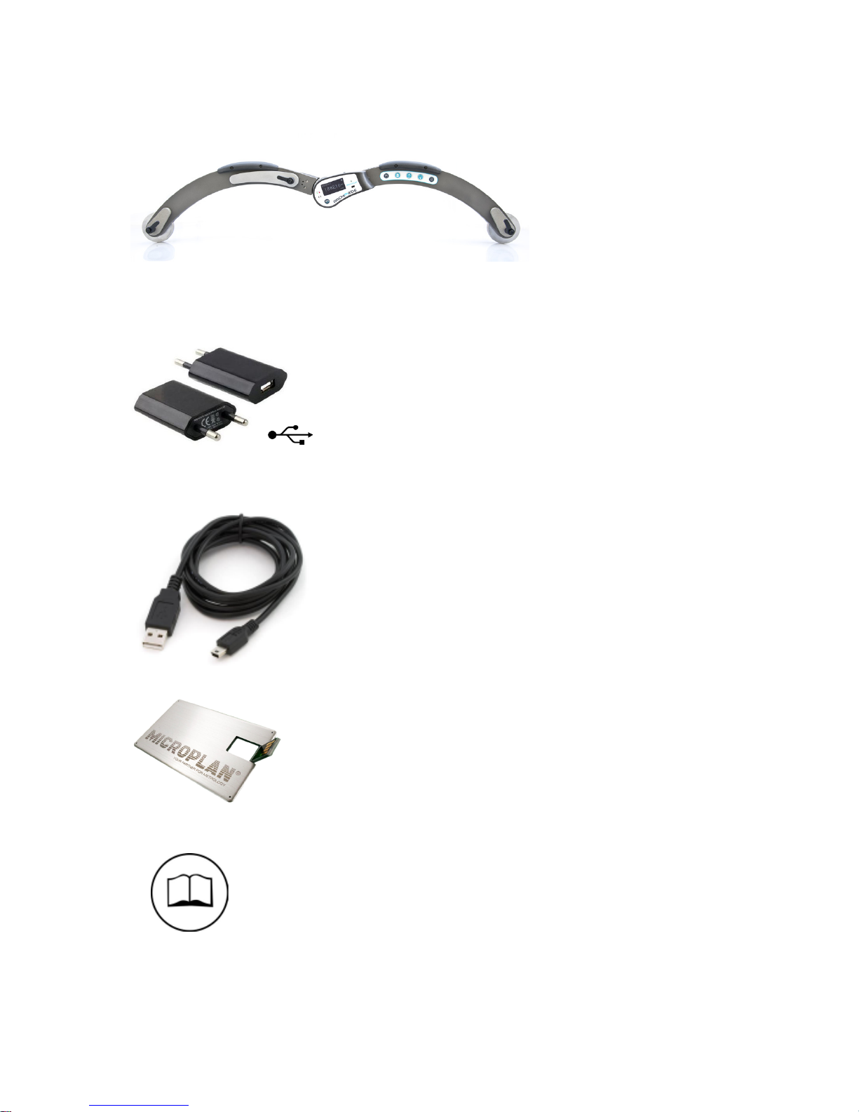
Components and accessoires
ARCHIMEDE
Large diameters measuring instrument
Battery charger
USB Card with «ARCHIMEDE» Software
USB cable for battery charging and
PC connection
Manual
Page 5
5
POWER
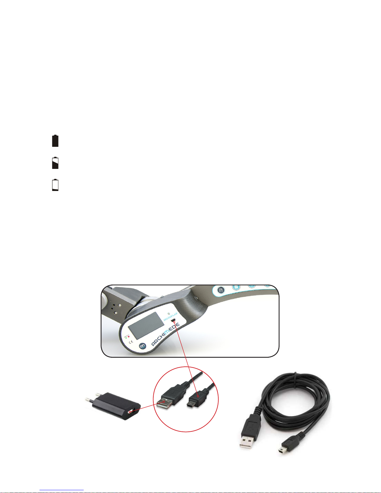
Archimede has an independent power supply with rechargeable batteries. The
batteries level is readable in the LCD display, the status indication is shown with a
small icon on the display:
Full charge
half charge
Low battery (auto-off)
In case of low battery automatically Archimede shuts off to prevent malfunctions and
inaccurate readings.
With battery fully charged Archimede can work up to 8 hours of continuous duty.
Page 6
6
BATTERY
CHARGING
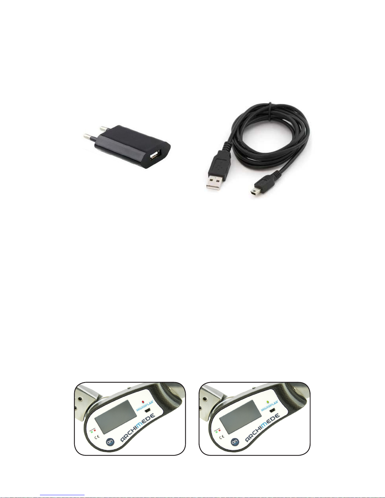
The instrument is supplied with USB Travel Adapter battery charger. You are not
allowed to use other chargers than the provided, that may damage the batteries and
the electronic devices inside the instrument.
Connect the supplied battery charger to the USB plug on the Archimede arm and let
it charge for about 6 hours. As an alternative to the power supply, the device can also
be charged by connecting it to a PC USB port.
Connect the supplied battery charger to the round plug on the Archimede arm and let
it charge for about 16 hours. Do not leave the battery charger constantly connected
to the AC power, to prevent overheating.
The bicolor LED, located on the main panel of the instrument shows two states with
the level of charge of the instrument:
Red led = batteries charging
Green led = batteries fully charged
Page 7
7
THE MEASURING PRINCIPLE
OF THE ARCHIMEDE HR
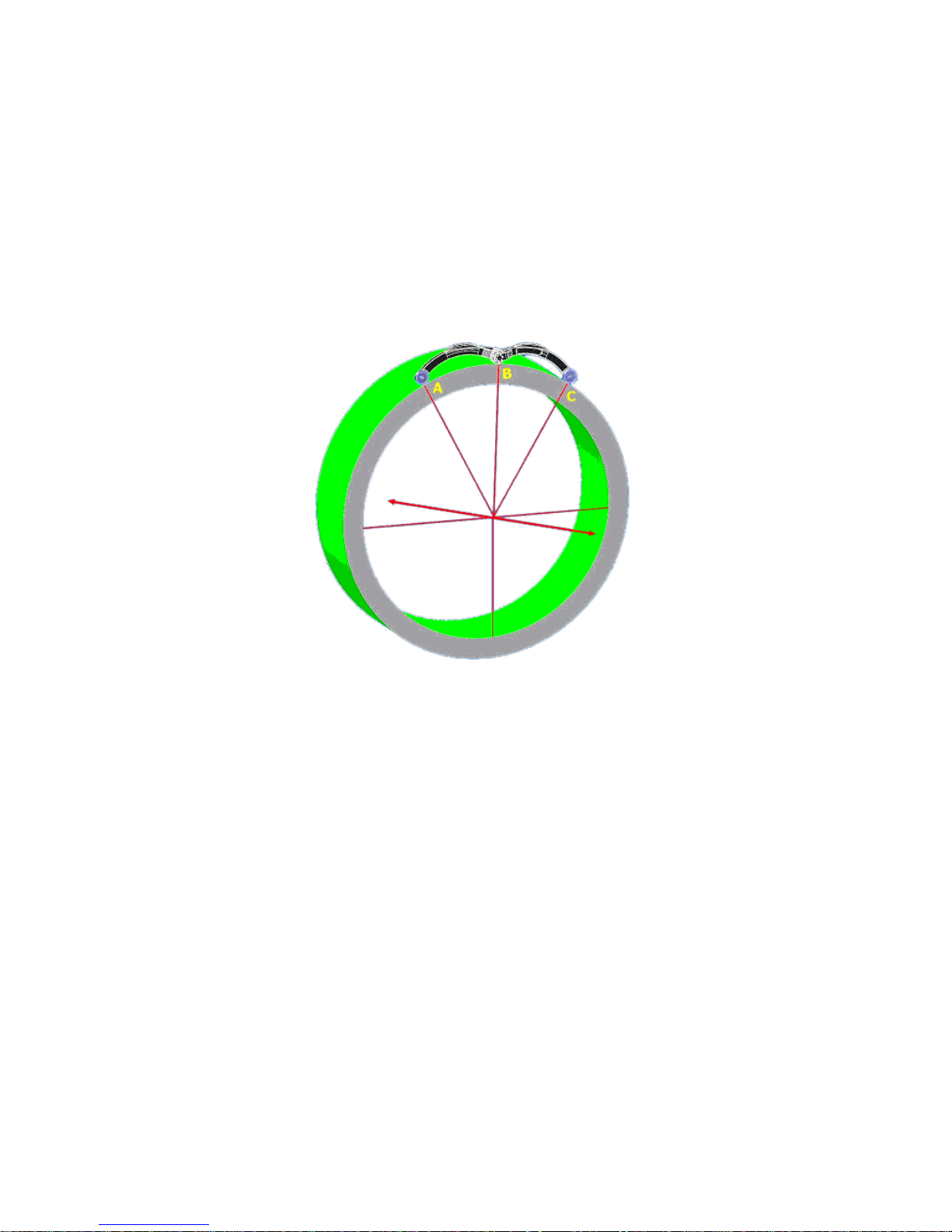
The Archimede HR is a measuring instrument which detects a circumference passing
through the three points of tangency (ABC) between the cylinder to be measured and
the instrument support points.
This type of measurement offers advantages in terms of:
1 • capability to measures outside diameters from 500 to 6000 mm with a
single instrument and with a single person,
2 • capability to perform measurements of internal diameters from 1100
to 6000 mm with a single instrument and with a single person,
3 • capability to perform up to 10 measurements on the same circumference and
consequently obtain the values of min, max and average diameter.
Page 8

8
IS THE ARCHIMEDE HR SUITABLE
TO MEASURE ALL KINDS OF LARGE DIAMETERS?
Archimede HR is a device that due to its given flexibility, can be used in many
production fields. Its measurement principle allows to obtain the stated accuracy
when measuring cylindrical parts that do not have irregular shapes, such as those
machined. The uncertainty in the diameter measurement is directly influenced by
the shape of the cylinder. This means that to achieve an accurate measure with Archimede HR with its stated Accuracy, a cylindrical piece of diameter of 1.000 mm
must have a circularity error of ± 0.04 mm for the HR model, of ± 0.06 mm for the
HA model and around ± 0.12 mm for the LA model. Otherwise it becomes necessary
to perform several measurements on the circumference and detect the value of the
average diameter.
DIAMETRO ARCHIMEDE LA ARCHIMEDE HA ARCHIMEDE HR
500 ± 0.045 mm ± 0.02 mm ± 0.018 mm
1000 ± 0.12 mm ± 0.06 mm ± 0.043 mm
1500 ± 0.245 mm ± 0.12 mm ± 0.085 mm
2000 ± 0.42 mm ± 0.21 mm ± 0.143 mm
2500 ± 0.645 mm ± 0.32 mm ± 0.218 mm
3000 ± 0.92 mm ± 0.46 mm ± 0.310 mm
4000 ± 1.62 mm ± 0.81 mm ± 0.543 mm
5000 ± 2.52 mm ± 1.26 mm ± 0.843 mm
6000 ± 3.62 mm ± 1.81 mm ± 1.21 mm
Tab.1 Archimede Uncertainty
However, it is possible to measure an irregular cylinder repeating the measurement
on different arcs of the same cylinder, to obtain the value of the average diameter.
In any case, the max measurement uncertain0ty for Archimede HR is shown in Tab.1
Page 9
9
IN CASE OF ELLIPTICAL CYLINDERS IS IT POSSIBLE
THE MEASUREMENT WITH ARCHIMEDE HR?
If the cylinder to be measured has a form error (ie. Elliptical cylinder), the instrument
Archimede HR returns the value of the diameter of a circle passing through the three
points of contact on the cylinder that is being measured: this last could have a
center not coincident with the workpiece one. This does not mean that Archimede
HR returns a bad measurement.
Keep in mind that in case of elliptical cylinders (ellipses) the calculation performed
by Archimede HR for each measurement is related to the best fit circumference
passing by the instrument support points. This means that it is not possible to
perform a single measurement, but it is required to detect a series of measures
diametrically opposed, from which obtain a value of Average Diameter.
In case it is necessary to measure a large size tube, if the shape error is high will not
be possible to determine a value of an average diameter of the piece, because the
circularity error of the cylinder makes it more similar to an ellipse or a polygon, that
by definition do not have geometric diameter.
Page 10
10
HOW WE PROCEED TO DETERMINE THE VALUE OF
THE AVERAGE DIAMETER WITH ARCHIMEDE HR?
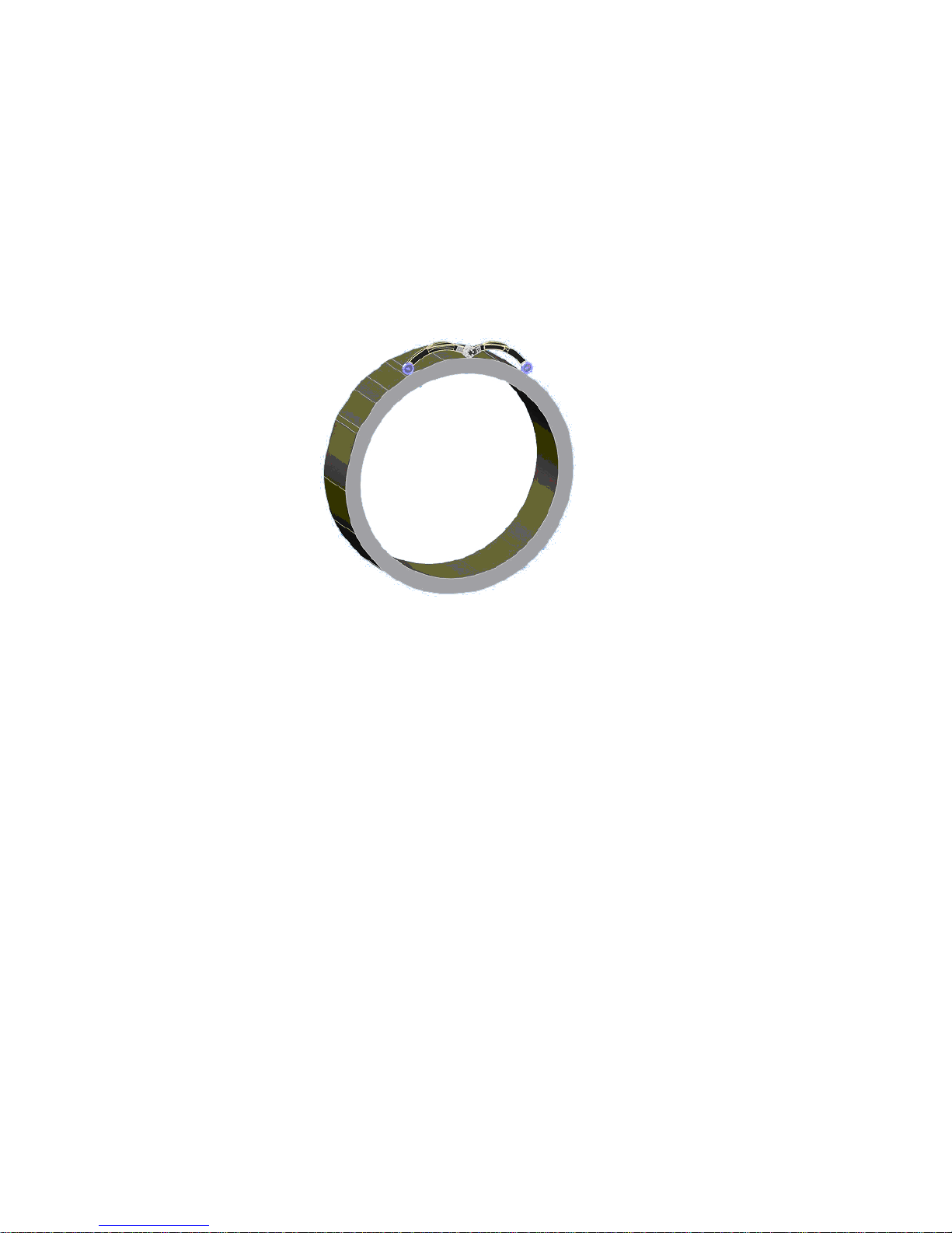
When you want to minimize the problem encountered of circularity error, it’s useful
to divide the cylinder circumference up to 10 arcs of 36°. On each arc is then taken
the diameter measurement, to obtain the value of the Average Diameter.
In case of measurement of a very irregular or deformed cylinder, the value of the
average diameter calculated by Archimede HR may not match with the value of the
diameter obtained with a two points measuring instrument as a caliper; that unlike
Archimede HR cannot detect circularity errors due to a number of deformation lobes
greater than 2 (the case of an irregular ellipse).
When we use a micrometer gauge or bore gauge for inner diameters, we are using
a two points measuring instruments. Such instruments are unable to detect the
circularity error in case of parts which have an odd number of lobes (3 or 5 lobes),
also if different angular position’s measurements are taken. With the two points
measuring instruments it is possible to estimate the circularity error only in the case
of parts which have two deformation lobes (ellipses).
Page 11
11
IN CASE OF IRREGULAR CYLINDERS IS IT POSSIBLE TO
MEASURE THEM WITH THE ARCHIMEDE HR?
It is possible to measure an irregular cylinder only by repeating the measurement
on different arcs of the same cylinder, to obtain the value of the Average Diameter.
It is impossible to perform a single-shot measurement to obtain an accurate diameter
value.
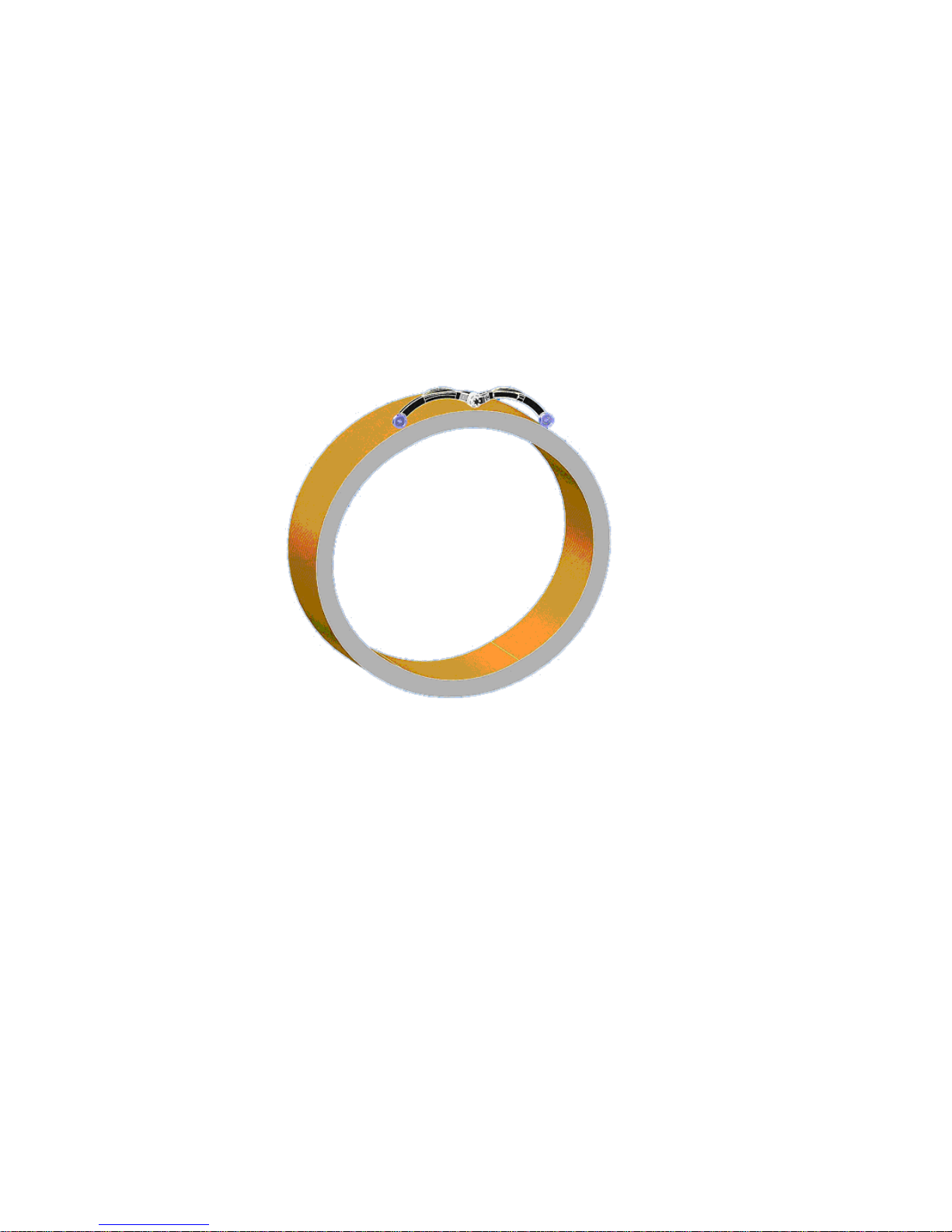
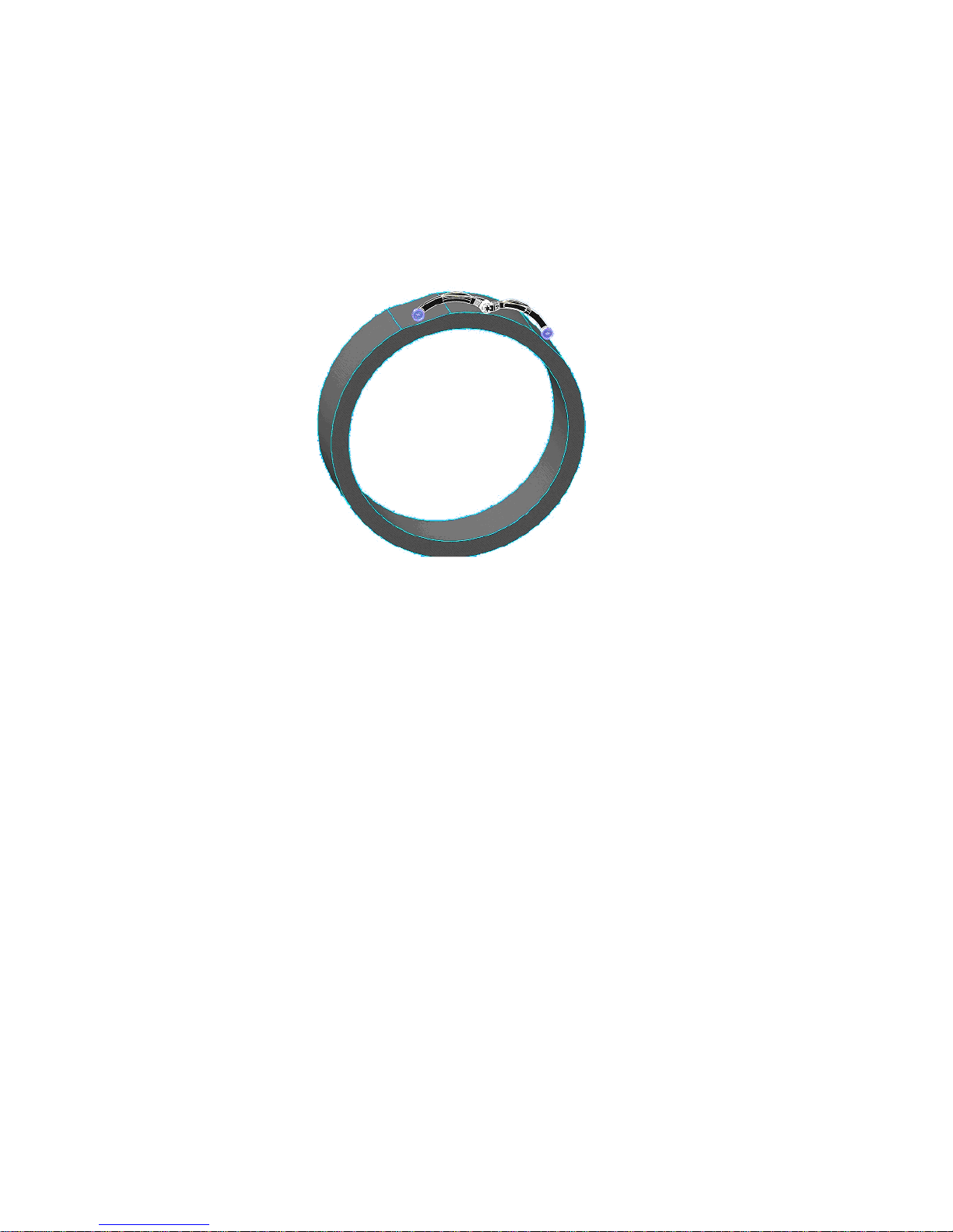
In the picture is shown a theoretical cylinder with two flat surfaces, that make it
a cylinder with a polygonal deformation. In this case, the value of the diameter
calculated by Archimede HR in the position shown in the picture, does not coincide
with any comparative measurement obtained from two points measuring instrument
as a caliper or an outside micrometer.
In fact, when the measure of the cylinder depicted above is taken with a caliper,
is obtained the diameter taking into account only one of the two flattened areas,
because the measurement is made taking the distance on two diametrically opposite
points.
With Archimede HR instead it is possible to determine the measure of the average
diameter (inscribed) of the circumference passing through both flattened areas, as
shown in the picture.
Archimede HR returns only and always diameter measurement of circles, while a
two points measuring device as a caliper, an outside micrometer or a two points bore
gauge, return only the measurement of lengths.
The measurements taken at two points and those taken with Archimede HR may be
coincident only if the measured piece has a limited form error, as indicated in Tab.1.
Page 12
12
HOW TO USE THE
ARCHIMEDE HR
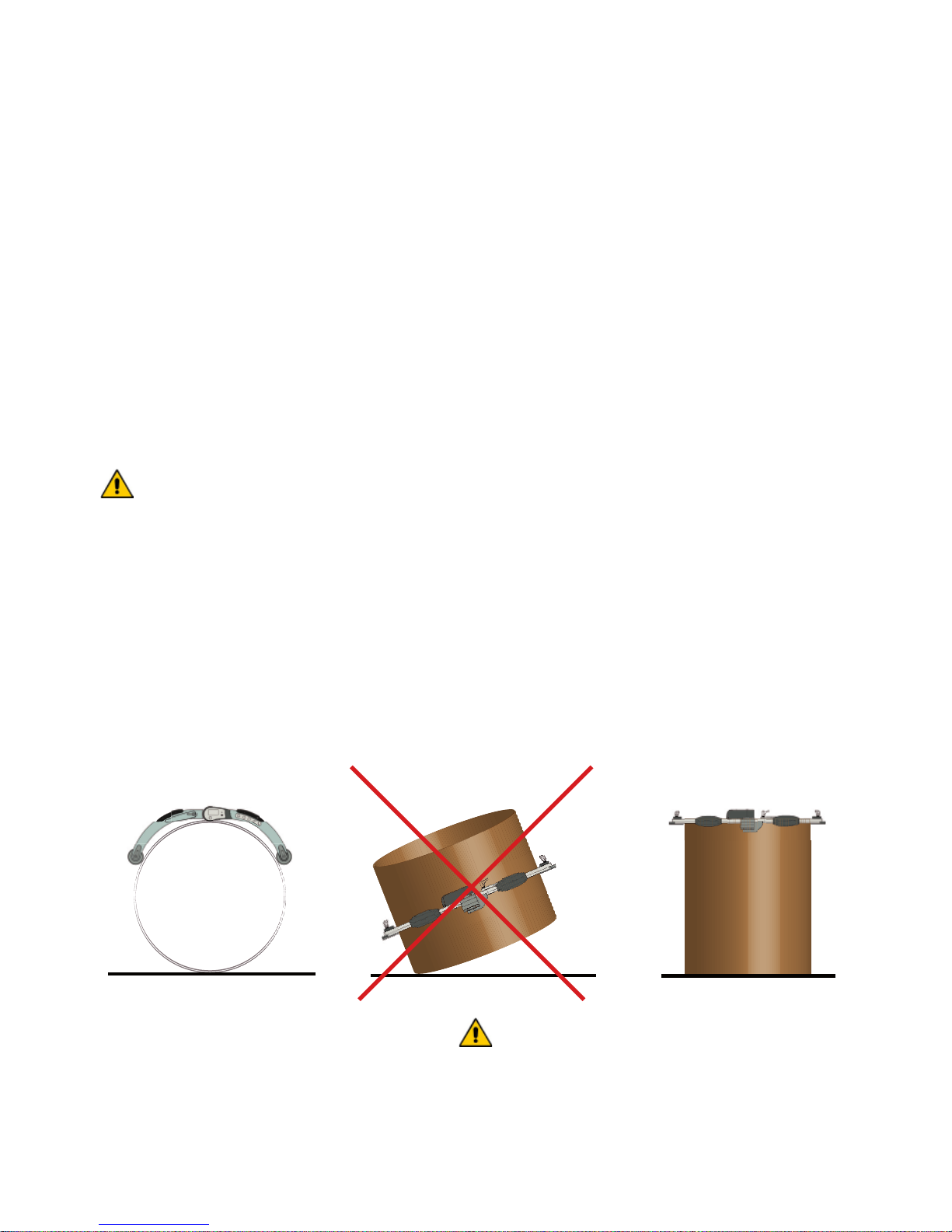
It is suggested to use the Archimede instrument following these two modes:
• according to a vertical plane perpendicular to the axis of the contact wheels
(ie the axis of the workpiece to be measured horizontally)
• according to an horizontal plane perpendicular to the axis of the contact wheels
(ie the axis of the workpiece to be measured vertically), using the central and lateral
mechanical stops for a more accurate measurement; to avoid the arms bending due
to the weight of the instrument.
It is not recommended any intermediate measuring mode between the two
modes described above, although it is possible to proceed with the measurement of
objects that are not well aligned with the floor; the resulting measure would not be
accurate and may be affected by errors due from various factors: mechanical strain
on the instrument arms, and the difficulty of maintaining the contact wheels resting
on the surface to be measured. In any case when it is possible, it is recommended
the use of mechanical stops (both in horizontal and vertical mode).
according to a vertical plane
perpendicular to the axis of the
contact wheels (ie the axis of
the workpiece to be measured
horizontally)
according to an horizontal plane
perpendicular to the axis of the
contact wheels (ie the axis of
the workpiece to be measured
vertically), using the central and
lateral mechanical stops for a
more accurate measurement; to
avoid the arms bending due to
the weight of the instrument.
Page 13

13
MENU DELLE FUNZlONl
Power on / off
To turn on and off the ARCHIMEDE, press the green ON / OFF button near the LCD display.
When you release the button the instrument goes off.
Zero setting of Archimede
The zero setting procedure of the instrument must be performed every time it is turned
on. The operator holding the instrument with the measuring arms joined, turn the instrument
on by pressing the green button. After a few seconds will be displayed the following text:
OPEN FROM JOINED ARMS
The operator then extends the instrument arms until the acoustic signal “beep” confirm the
zero setting achieved.
It is now possible to perform measurements of both external and internal diameters. To make
a new zero-setting, turn the instrument off by pressing the green ON / OFF button, and repeat
the same procedure described above.
Reading and measurements
After the Archimede has been turned on, the display shows the serial number; meanwhile
zero-setting has been performed (see above), the instrument is ready for measurements: the
display will show the following texts spread over 3 raws:
Raw 1 Ø EXT. mm or Ø EXT. in
in the second raw appears in a larger font, the value of the calculated diameter of the best
fit circle, tangent to the instrument three support points
Raw 2 936,38
In the third raw is shown:
Raw 3 M X
where “X” indicates the number of readings that have been saved, to be used for the
calculation of the average diameter.
Page 14
14
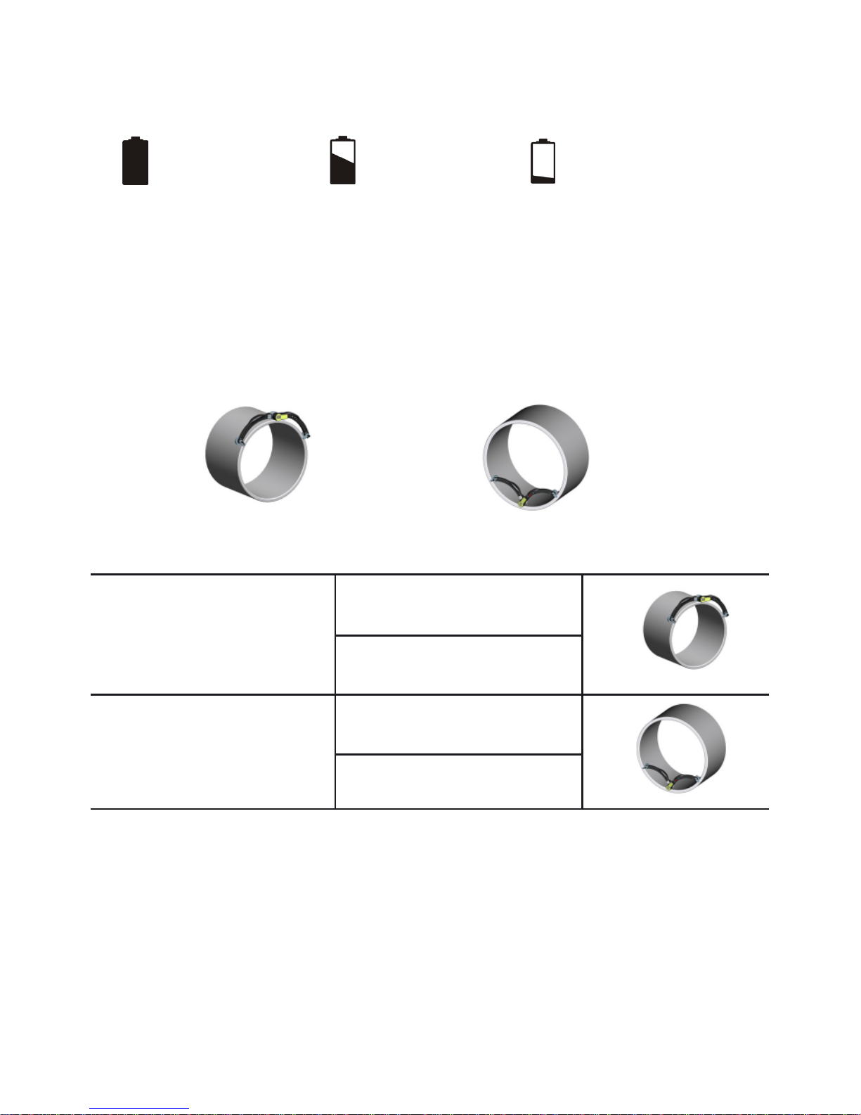
A small icon on the display, at the bottom right; shows the battery charge status.
= full charge = half charge = low battery
The maximum number of readings that can be stored is 12.
The instrument is able to recognize the angle between its arms and then arrange automatically
the measurement of an internal or an external diameter. The display shows the mode of
measurement with the two following written:
Riga 1 EXT oppure INT
Archimede measuring range is:
External diameters: minimum: 500 mm
maximum: 6000 mm
Internal diameters minimum: 1100 mm
maximum: 6000 mm
In case of reading out the measuring range, the display shows the following text:
OVER RANGE
in case the measurement exceeds the maximum or the minimum measurable value.
Page 15

15
Calibration and factory settings
The instrument Archimede is calibrated at 20° ± 1°C reference temperature: this calibration
is called “factory set”. In the event that the instrument it’s used at a temperature that vary
from the reference one; after setting the zero, it’s recommended to perform the calibration
procedure “OT MODE” or “Out of Temperature”. This operation must be executed with the
aim of a precision surface plate or a granite straight rule (Art. PN / RL).
Calibrazione “OT MODE”
Quando si utilizza Archimede ad una temperatura diversa da 20° C ± 1° C è necessario
procedere ad una calibrazione dello strumento per una misura più accurata e precisa, come
di seguito illustrato:
1. Posizionare lo strumento acceso aprendo i bracci a 180° e appoggiando le due ruote e il
mozzo di appoggio al piano di riscontro o al regolo, precedentemente messo in bolla.
2. Press the MENU button, select “INITIALIZE” and then “OT MODE”: the display will show
the message: “Place Archimede at 180 ° within 10 seconds”.
3. After some seconds it will be displayed the “CALIBRATION DONE” message with an acoustic
beep that indicates the completion of the instrument calibration.
4. The display will show the continuous angle readouts, showing also the icon OT in the lower
right corner. This reminds the operator that the instrument is working in “Out of Temperature”
mode, not according to the factory calibration, in order to ensure more accurate measurements
at the current temperature conditions.
When the power is turned off, the factory settings are restored and the mode “OT MODE”
disabled. It is possible, without turning off the power, to disable the “OT MODE” via MENU /
INITIALIZE / OT MODE / DISABLE.
Page 16
16
Memorizzazione delle letture
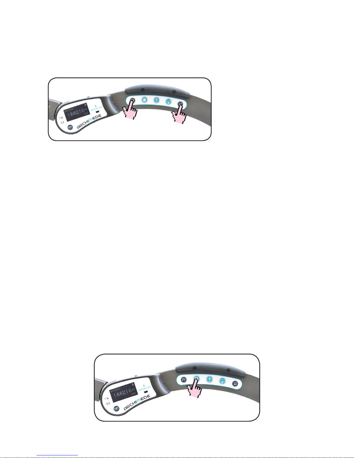
It is possible to store up to 12 readings, and obtain the arithmetic mean. In order to
obtain this, once achieved a stable measurement, press the SAVE button on the right
arm of the instrument.:
Pressing the SAVE button the current measurement is stored in memory, and in the
bottom right corner is shown the number of stored measurements.
Reading of average diameter
To view the stored measurements, press MENU / MEMORY / VALUE SAVED on the
control panel. The measures will be displayed listed as follows:
1 - 545.76 mm est
2 3 -
To view the arithmetic mean of the stored readings, press the MENU / MEMORY /
AVERAGE VALUE on the control panel.
Clearing memory
To clear the instrument memory, thus erasing all the readings previously
stored, select MENU / STORE / CLEAR MEMORY. An acoustic signal (beep)
will confirm the clearing completion.
Page 17
17
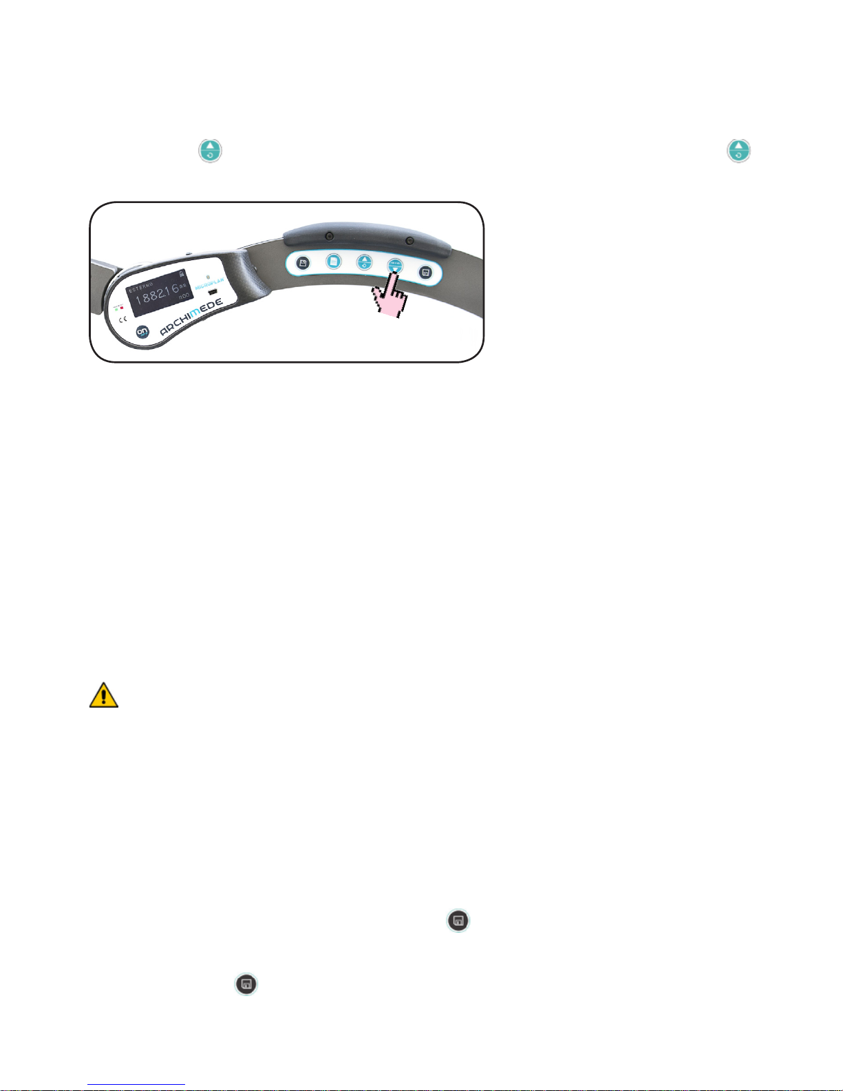
Rotation of the messages on the display
To facilitate the reading on the display under particular conditions of measurement,
it is provided a function of rotation of 180 ° of the shown messages on the display,
pressing the button. To return to the normal display setting, press the
button again.
Measurement units
To set the measurement units, select MENU / SETTINGS / MEASURES / UNITS:
then select the preferred measurement units between mm and inches.
Measurement type
You can select to display the measurements as diameters or angles. Press MENU /
SETTINGS / SIZES /MEASUREMENT TYPE and choose between diameters and angles.
In the angular measure mode, you cannot store any measurement. To get again
the saving measures displayed, switch back to the DIAMETERS mode, selecting
MENU / SETTINGS / SIZES / MEASUREMENT TYPE.
Absolute or Relative Measurement (ABS / REL)
The instrument by default, supported on three points aligned onto a straight surface,
returns a measure of 180 ° absolute angle (ABS). To use a “relative” (REL) reference
rather than an absolute one (ABS); press the button for 5 seconds and wait until
the beep: the relative mode will be indicated with the message (REL) shown on the
display in the top right. To restore the measuring absolute (ABS) mode, press again
for 5 seconds the button and wait.
Page 18
18
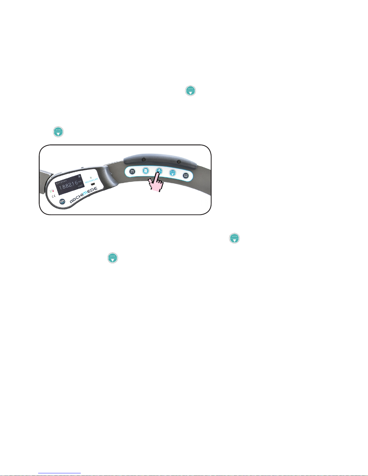
Reading of maximum and minimum values
In order to make the diameters measurement easier, especially when the instrument
is not orthogonally positioned with the workpiece axis that is being measured; has
been implemented the “Minimum Value Reading” function, that shows on the
display the minimum value detected by the instrument during the measuring process.
This function is activated by pressing the button on the arm of the instrument.
When measuring an outer diameter appears in all measurements the minimum value
reached. The “minimum” is displayed in the lower left. To exit this function, press
the sul braccio dello strumento.
It is possible, in the same way, to read the maximum value by activating the
“maximum” function. To access this feature, press the button 3 times, until the
instrument display shows the message “maximum” on the bottom left. To exit this
function, press the button on the instrument arm.
MAINTENANCE AND PERIODIC CHECKS
The Archimede instrument does not requires special maintenance operations. It is
recommended, however, to proceed to the regular cleaning of the wheels, and in
particular of the central hub magnets placed on its lower surface. You can easily
clean the magnets with compressed air or repeatedly applying and removing a strip
of paper adhesive tape in order to remove dust and metal chips that may affect the
support of the hub and thereby create measurement error.
To ensure good reliability and accurate measurements, it is recommended a periodic
inspection each 12 months. For any questions or information on the maintenance
and calibration of the instrument our technical department is available.
Page 19
19
IMPORTANT REMARKS
FOR A PROPER MEASUREMENT
The Archimede instrument measures the circumference diameter fitted through
three points of contact identified by the instrument supports (the central one and
the two wheels at the ends of the arms). Should be taken in mind that, in case of
shape error of the object to be measured, will be obtained measurements influenced
by the same error.
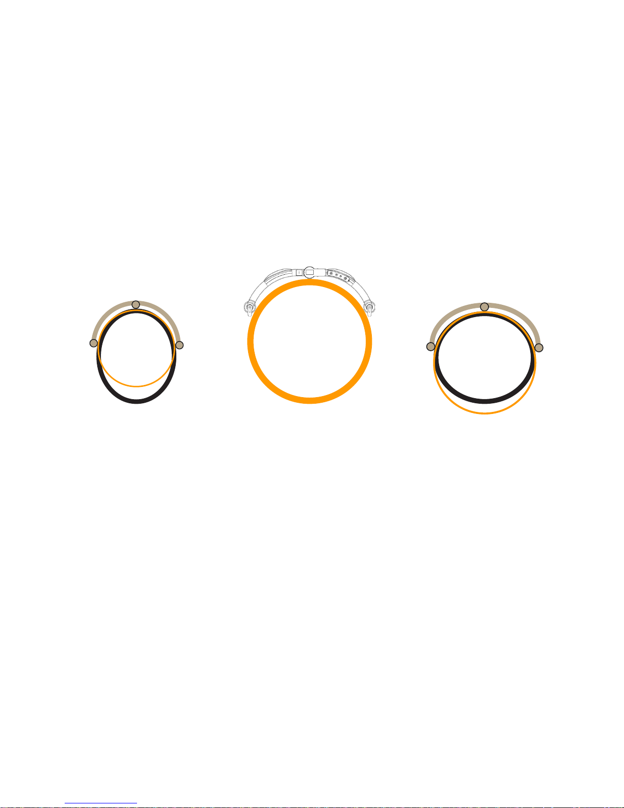
Shape error examples:
Ideal circumference
The solution to have a valid measurement is to use the “average” function, provided
by the instrument; thus measuring the object at several arcs in order to obtain the
averaged value of the diameters measured.
To perform a correct measurement it’s very important the way how the instrument is
used. The two arms in titanium are the most stiff solution that can be achieved with
a certain weight: although the load generated by the operator onto the Archimede
arms while measuring, produces a minimum deflection, that may result in a variation
on the angular measurement: these variation become significant in case of large
diameters measurements.
To avoid this influence, it is strongly recommended to hold the instrument without
pressing the arms against the object to be measured, using when possible the
mechanical stops.
The measured diameter
will be lower then the
ideal circumference.
The measured Diameter
will be bigger then the
ideal circumference.
Page 20

 Loading...