

Dragonfly DFRM-TAB-100-HC, DFRM-NTT-100-ALR, DFRM-TAB-110-MW, DFRM-TAB-100-UW, DFRM-TAB-110-HC Installation Manual
...
INSTALLATION MANUAL
Recessed In-Ceiling Motorized Projection Screen
DFRM Installation Manual
Pg. 2
© 2016 Dragonfly
Important Safety Precautions and Warnings
Warning: To reduce the risk of fire or electric shock, do not expose this apparatus to rain or moisture.
1. Read and understand all instructions before using.
2. Do not use this apparatus near water.
3. Clean the screen housing only with a dry cloth.
4. Do not block any ventilation openings. Install according to manufacturer’s instructions.
5. Do not install near any heat sources such as radiators, heat registers, stoves or other
apparatus (including amplifiers) that produce heat.
6. Care must be taken as burns can occur from touching hot parts.
7. Do not operate appliance with a damaged cord or if the appliance has been dropped or
damaged - until it has been examined by a qualified
8. Position the cord so that it will not be tripped over, pulled, or contact hot surfaces.
9. If an extension cord is necessary, a cord with a current rating at least equal to that of the
appliance should be used. Cords rated for less amperage than the appliance may overheat.
10. To reduce the risk of electric shock, do not disassemble this appliance, but take it to a
qualified serviceman when service or repair work is required. Incorrect reassembly can cause
electric shock when the appliance is used subsequently.
11. The use of an accessory attachment not recommended by the manufacturer may cause a risk
of fire, electric shock, or injury to persons.
12. SAVE THESE INSTRUCTIONS.
CAUTION
CAUTION: TO REDUCE THE RISK OF
ELECTRICAL S HOCK.
DO NOT REMOVE COVER. NO USER
SERVICEABLE PARTS INSIDE.
REFER SERVICING TO QUALIFIED
SERVICE PERSONNEL.
The lightning flash with arrowhead symbol,
within an equilateral triangle, is intended to
alert the user to the presence of uninsulated
dangerous voltage within the product’s
enclosure that may be of sucient magnitude
to constitute a risk of electric shock to
persons.
The exclamation point within an equilateral
triangle is intended to alert the user to
the presence of important operating and
maintenance (servicing) instructions in the
literature accompanying the appliance.
Before unpacking the projection screen, read the entire manual to become
familiar with the steps involved for installation and operation. Dragonfly is not
responsible for any damage or injury that occurs from incorrect installation or
operation.
DFRM Installation Manual
Pg. 3
1. Introduction
Thank you for purchasing a Dragonfly™ Motorized Projection Screen. Designed to be easy to
operate, reliable, and hidden away when not in use, this screen is guaranteed to provide years of
maintenance-free operation and enjoyment.
These screens feature several convenient mounting methods, can be controlled manually or
automatically by a control system or projector, and are fully adjustable. The screen material includes
a black, light-proof backing and optional adjustable tension tabs along each side to keep the
screen perfectly flat during use.
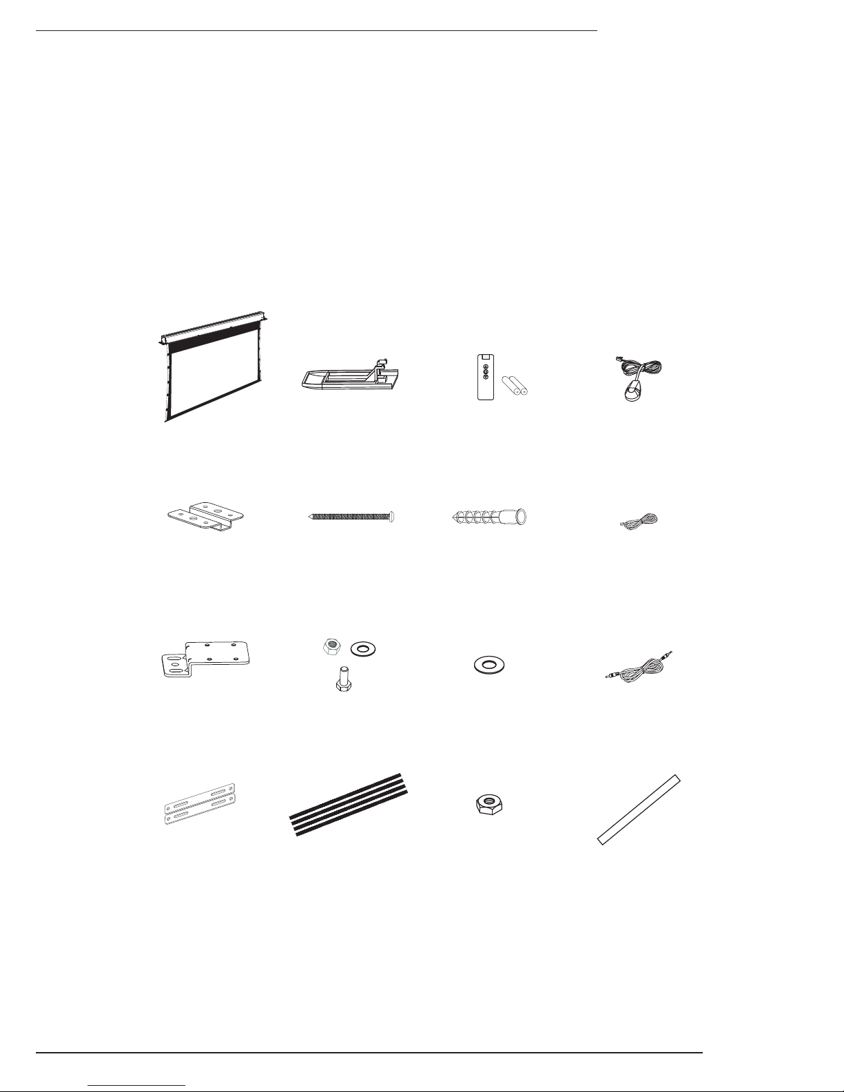
2. Package Contents
1x Projection
Screen
DC 12V Trigger
Cable 33’ (1)
RJ12 Control
Cable 10’ (1)
1x RF Remote
Ceiling Brackets
(2)
Housing Z Brack-
ets (2)
Mounting Bracket
Hardware (8 each)
M10 Nuts for
Threaded Rod (16)
Housing Door
Panel (1)
End Caps (2)
Mounting Anchors
(8)
M6 Concrete/
Wood
Ceiling Bolts (8)
IR Receiver
1 Meter M10
Threaded Rod (4)
Housing Flat
Brackets (2)
M10 Washers for
Threaded Rod (16)
Not pictured: Electrical junction box and power cable (attached to housing)
DFRM Installation Manual
Pg. 4
© 2016 Dragonfly
3. Installation
Important! Before installation, ensure that the ceiling structure is capable of
supporting the weight of the screen. Screen weights are listed in section, "7.
Assembled Weights" on page 13.
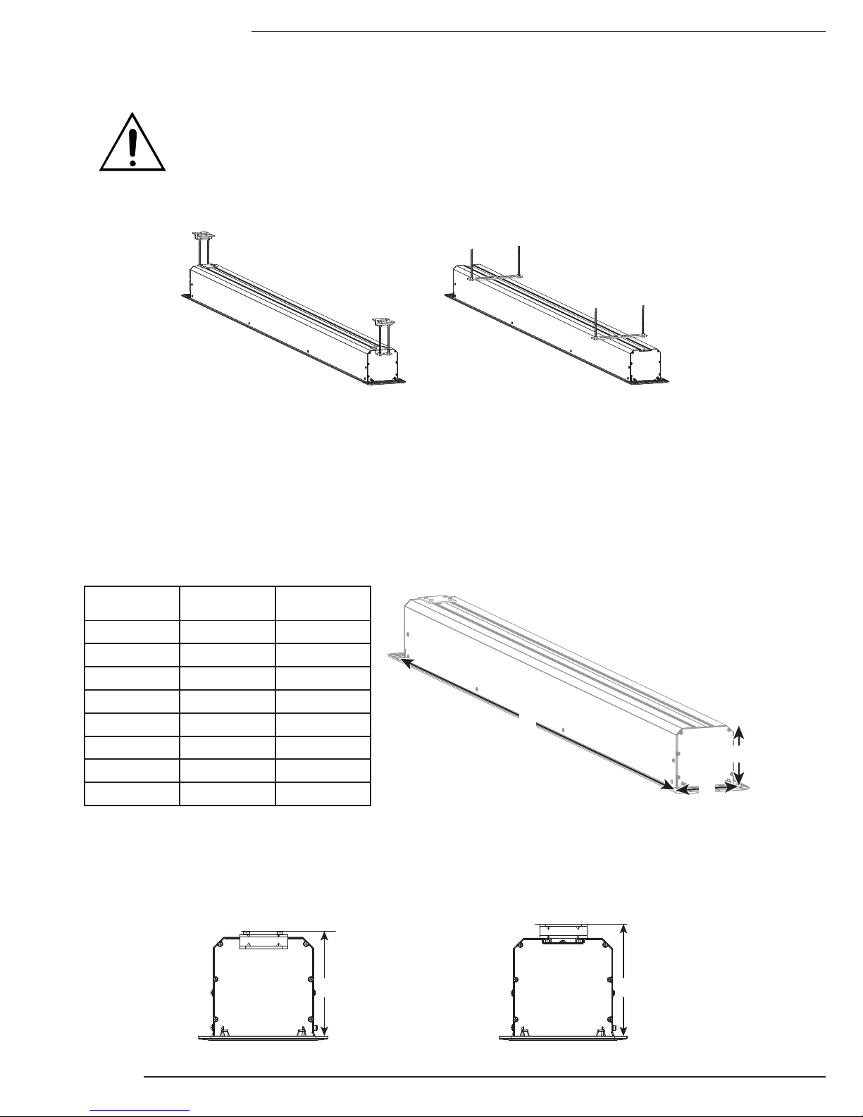
Step 1. Determine the Mounting Method
Z Brackets Flat Brackets
• Z Brackets – Used for all installations with new or existing permanent ceilings and when there
is no access above the screen housing such as an attic or a crawl space.
• Flat Brackets – Used for installations with new ceiling and access above the screen at all
times, such as a commercial tile ceiling, an attic, or a crawl space.
Step 2. Prepare the Ceiling Opening
Screen Housing Cutout
Use the chart to determine the opening size for the housing, then cut the ceiling surface.
Type-Size Length (A) Width (B)
A
B
C
TAB-100" 112.53" 7.25"
TAB-110" 121.19" 7.25"
TAB-120" 130.05" 7.25"
TAB-130" 138.79" 7.25"
NTT-100" 103.28" 7.25"
NTT-110" 111.90" 7.25"
NTT-120" 120.50" 7.25"
NTT-130" 129.30" 7.25"
Height Clearance (C)
Dimensions measured from bottom of ceiling surface to top of screen housing including height of
mounting bracket and hardware.
Z Bracket Down/Flat Bracket Z Bracket Up
7.0" 7.5"
DFRM Installation Manual
Pg. 5
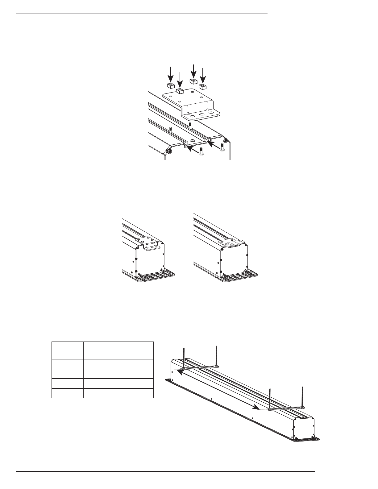
Step 3. Install the Mounting Brackets
The mounting brackets are secured using hardware that slots into the rails on top of the housing.
Slide the bolts into the rail, position the brackets over the bolts, and tighten the nuts onto the bolts.
Z Bracket Installation
Point the brackets DOWN for threaded rod/suspended mounting or UP for direct ceiling mounting.
If the brackets are installed facing UP, position the bend in the bracket flush with the edge of the
screen housing.
DOWN UP
Straight Bracket Installation
Install the brackets a minimum distance apart to prevent instability after hanging the screen
housing. The brackets may be positioned o-centered as needed to fit the ceiling structure.
Size
Minimum Bracket
Separation
100" 73.20"
110" 78.97"
120" 84.88"
130" 90.71"
 Loading...