

Dragonfly DFM-TAB-84, DFM-TAB-92, DFM-TAB-106, DFM-TAB-110, DFM-TAB-120 Installation Manual
...
INSTALLATION MANUAL
Motorized Tab-Tension Projection Screens
Pg. 2
© 2013 Dragony
DFM-TAB Installation Manual
1. Important Safety Precautions and Warnings
To reduce the risk of re or electric shock, do not expose this apparatus to rain or moisture.
The lightning ash with arrowhead symbol, within an equilateral
triangle, is intended to alert the user to the presence of un-
insulated dangerous voltage within the product’s enclosure that
may be of sufcient magnitude to constitute a risk of electric
shock to persons.
The exclamation point within an equilateral triangle is intended
to alert the user to the presence of important operating
and maintenance (servicing) instructions in the literature
accompanying the appliance.
1. Read and follow all instructions and warnings in this manual. Keep for future reference.
2. Do not use this apparatus near water.
3. Clean the screen housing only with a dry cloth.
4. Do not block any ventilation openings. Install according to manufacturer’s instructions.
5. Do not install near any heat sources such as radiators, heat registers, stoves or other apparatus (including
ampliers) that produce heat.
6. Do not override the safety purpose of the polarized or grounding-type plug. A polarized plug has two blades - one
wider than the other. A grounding type plug has two blades and a third grounding prong. The wide blade or the
third prong is provided for your safety. If the provided plug does not t into your outlet, consult an electrician for
replacement of the obsolete outlet.
7. Protect the power cord from being walked on or pinched particularly at plug, convenience receptacles, and the
point where it exits from the apparatus.
8. Only use attachments/accessories specied by the manufacturer.
9. Use only with a cart, stand, tripod, bracket or table specied by the manufacturer, or sold with the apparatus.
When a cart is used, use caution when moving the cart/apparatus combination to avoid injury from tip-over.
10. Unplug this apparatus during lightning storms or when unused for long periods of time.
11. Refer all servicing to qualied service personnel. Servicing is required when the apparatus has been damaged in
any way, such as when the power-supply cord or plug is damaged, liquid has been spilled or objects have fallen
into the apparatus, the apparatus has been exposed to rain or moisture, does not operate normally, or has been
dropped.
12. Do not expose this equipment to dripping or splashing; ensure that no objects lled with liquids, such as vases,
are placed on the equipment.
13. To completely disconnect this equipment from the AC mains, disconnect the power supply cord plug from the AC
receptacle.
Warning:
CAUTION
CAUTION: TO REDUCE THE RISK OF
ELECTRICAL SHOCK.
DO NOT REMOVE COVER. NO US ER
SERVICEABLE PARTS INS IDE.
REFER SERVICING TO QUALIFIED
SERVICE PERSONNEL.
Before you unpack the projection screen, read the entire manual to become familiar with the steps
involved for installation and operation. If you feel uncomfortable performing any of the steps
required, stop and consult a qualied installation professional. Dragony is not responsible for
any damage or injury that occurs from incorrect installation or operation.

DFM-TAB Installation Manual
Pg. 3
www.snapav.com Support: 866.838.5052
1. Important Safety Precautions and Warnings
2. Overview
3. Package Contents
4. Pre-Installation
4.1. Required for Installation
4.2. Unpacking the Projection Screen
4.3. Powering the Screen
4.4. Mounting Considerations
4.5. Control Method
5. Installation
5.1. Installing the Brackets
5.1.1. Mounting Brackets
5.1.2. Hanging Mount
5.2. Installing the Screen on the Brackets
5.3. Test the Screen
6. Control Setup
6.1. Control Wiring Diagram
6.2. IR Control (With Optional IR Receiver Extension)
6.3. 12 Volt DC Trigger Cable
6.4. Manual Wall Switch
6.5. RS232 Serial Control
6.6. Contact/Relay Control
6.7. EXT CTRL Port Wiring Diagram
6.8. Extending Control Wiring
6.8.1. Wall Switch
6.8.2. Contact Closure or RS232 Control
7. Screen Adjustments
7.1. OPEN Limit Adjustments
7.2. CLOSED Limit Adjustments
7.3. Tab Tension Adjustments
8. Using the Screen
8.1. Automated Control
8.2. Manual Control
9. Cleaning the Projection Screen
10. Troubleshooting
11. Specications
12. Dimensions and Weight
13. Warranty
14. Contacting Technical Support
Table of Contents
2
4
4
5
5
5
5
5
5
6
6
6
7
8
8
9
9
9
9
9
9
9
10
10
10
10
11
11
11
12
13
13
13
13
14
14
15
16
16
Pg. 4
© 2013 Dragony
DFM-TAB Installation Manual
2. Overview
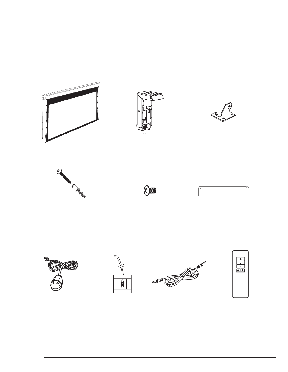
3. Package Contents
Projection Screen (1) Hanging Brackets (2) Ceiling Hanger Adapter (2)
5x40mm Mounting Screws (8)
(inc. Optional Concrete Anchors)
External IR Receiver (1) Wall Switch (1)
12V Trigger
Wire (1)
Remote Control (1)
Allen Key (1)
M5x10 Ceiling
Hanging Screws (4)
Thank you for purchasing a Dragony™ Motorized Projection Screen. These projection screens can be hidden
away when not in use and are designed to be easy to operate and reliable.
They feature several convenient mounting methods, can be controlled manually or automatically by a control
system or projector, and are fully adjustable. The screen material includes a black, light-proof backing and
adjustable tension tabs along each side to keep the screen perfectly at during use. This screen is guaranteed to
provide years of maintenance-free operation and enjoyment.
DFM-TAB Installation Manual
Pg. 5
www.snapav.com Support: 866.838.5052
4. Pre-Installation
Before installing the projection screen, review this section thoroughly to be sure that no additional work is needed
to prepare the job for mounting and controlling the screen.
4.3. Powering the Screen
Operating Voltage: 110 Volts AC
Amperage: .96 Amps
The screen has a ve foot power cable permanently attached to the left side of the screen as seen from the
viewing area. Install or locate a receptacle close enough to plug the screen in prior to installation.
4.5. Control Method
Dragony motorized screens can be controlled via manual wall switch, IR remote, 12 volt trigger, or RS232.
Complete instructions for each method are described in the Control Setup section (Page 8). Decide on the method
that will be used before installation begins. Pre-wire any cables from projectors or control systems prior to closing
the walls or ceiling.
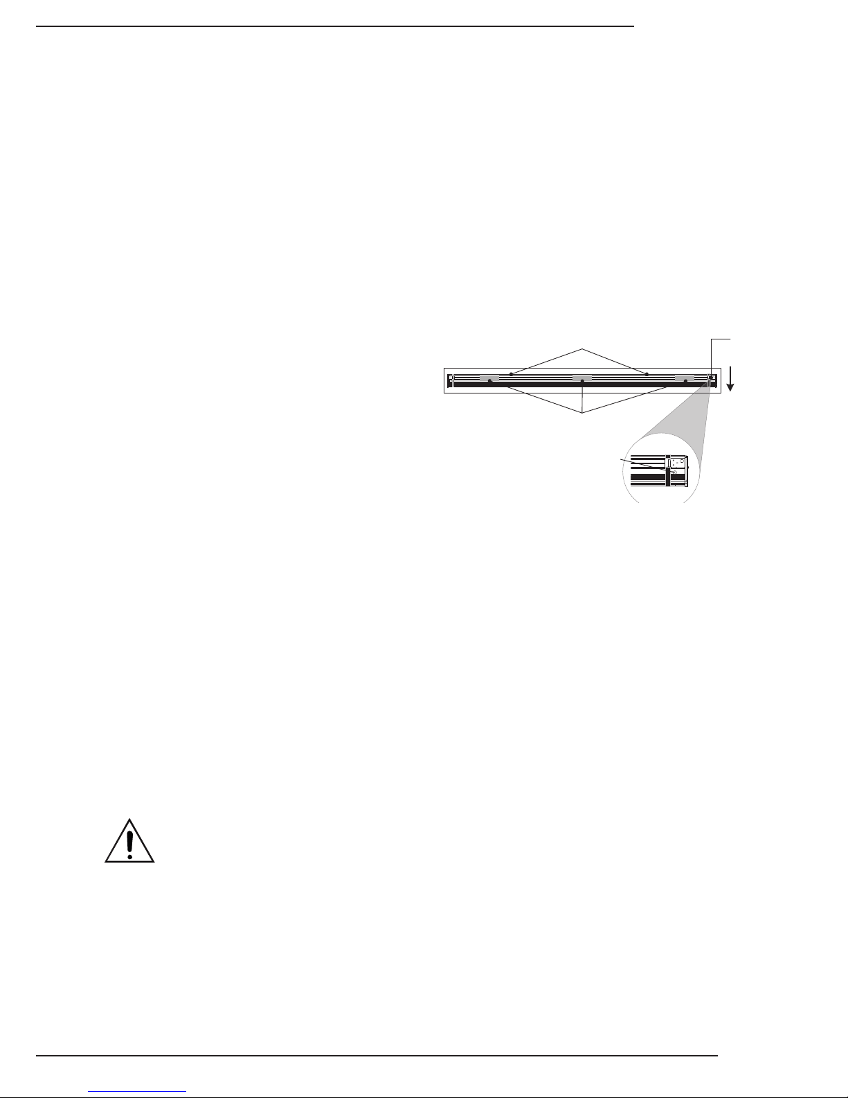
4.2. Unpacking the Projection Screen
As you unpack the projection screen:
• Remove all accessories from the box before
discarding any packaging. Use the Package Contents
section to verify that everything has been removed.
• After the screen is out of the packaging, remove
the tape holding the bottom rail of the screen in the
housing.
• Do not remove the black bands from the ends of the
projector until it has been mounted. These bands
keep the bottom bar from falling into the housing and
getting stuck.
• While unpacking and preparing the projection screen for installation, take note of the location of the adjustment
screws and grommet. It may be difcult to locate them after the screen is hanging from the mounting brackets.
• Do not turn the adjustment screws until the screen is mounted and ready to be adjusted.
4.1. Required for Installation
Have an assistant help with installation to prevent damage or injury. The following tools will be needed to complete
the installation:
• Phillips Screwdriver
• 2 Step Ladders
• Electric or Cordless Drill
• Marker
• Level
• 7/32” Masonry Drill Bit to install 8mm concrete anchors
• 5/32” Drill Bit to install 6mm Wall Switch Screw anchors (optional)
Remove (2) Screws Holding Bar in Place
(Back of Housing)
Viewing
Area
Adjustment
Screws
Adjustment Screw
Grommet Location
Remove
Tape
4.4. Mounting Considerations
The design of the brackets allows for wall, ceiling, or hanging mounting. Plan the nal height of the screen’s
viewing surface prior to installation. Make sure there is enough room for the screen to hang freely below the
mounting location when extended.
Warning! The building structure and material in the mounting location must be capable of safely supporting
the weight of the projection screen. Included hardware is only meant for use with wood, surfaces with
wood bracing behind them, or concrete surfaces. Conrm with an engineer or contractor that the building
material will safely support the weight of the screen using the included mounting hardware.
Pg. 6
© 2013 Dragony
DFM-TAB Installation Manual
5. Installation
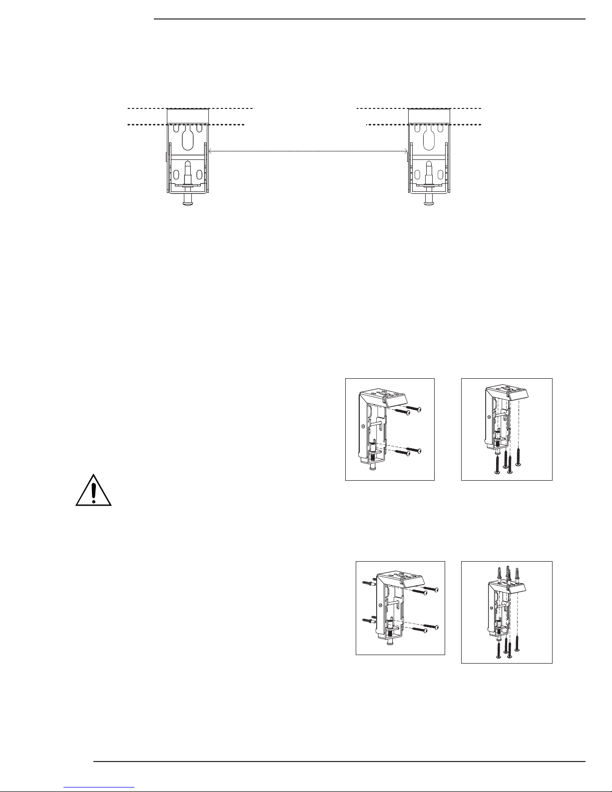
5.1.1. Mounting Brackets
Top of Screen Housing Will Be Here
Top of Brackets Must Be Level
Approximate Distance = Screen Housing Width Minus 8"
The mounting brackets can be attached anywhere on the screen housing, but they should be about 4” from
each end to ensure that vibration or noise is prevented during operation.
1. Measure the width of the Projector Screen Housing (Dim. “B” in Section 12. Dimensions and Weight) and
subtract 8” to estimate the distance the brackets should be mounted apart.
2. Mark the location of one bracket on the mounting surface, then measure to the planned location of the second
bracket. Adjust the general location of each bracket to allow for both to mount securely to wood or concrete.
Be sure that wall-mounted brackets are level before installation.
3. Mark the screw holes for each bracket and install them:
Mounting to Wood Joists or Studs
Use the included mounting screws to secure the projector
mount brackets to the surface.
• No pre-drilling is necessary for most applications.
• Use 4 of the 8 included screws to mount each bracket
as pictured.
Mounting to Concrete Ceiling or Wall
Use the included anchors for the mounting holes and install
the screws into the anchors.
• Use a 7/32” masonry bit to drill a hole for each screw.
• Insert the anchors into the holes until they are ush.
• Do not install anchors into mortar joints.
• Use 4 of the 8 included screws to mount each bracket
as pictured.
Warning! If holes are pre-drilled, use no
larger than a 5/32” bit. Larger holes will not
properly grip the threads, and the projection
screen could fall.
Wall Mount
Wall Mount
Ceiling Mount
Ceiling Mount
5.1. Installing the Brackets
 Loading...