

Dragonfire Group 0018423541 User Manual

Chapter 1 Transceiver
1WCS - Transceiver Manual
1
This guide is intended to provide information on the transceiver component of PickPoint’s Will Call System (WCS). This guide briefly covers it’s intended use, physical features, functional requirements, physical and logical setup and includes a diagram that visually reresents how the transceiver works with the overall system.
Caution:
This user manual shall be used solely for the intent for which it was created; to provide
information on the transceiver used with PickPoint’s WIll Call System (WCS). Any
changes or modifications not expressly approved by the manufacturer - Dragonfire Group
Holdings LTD. - can void the user’s authority to operate the equipment.
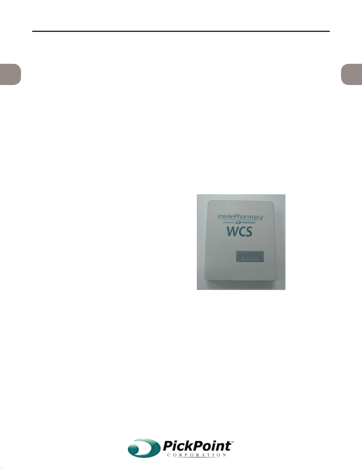
1.1 Description
This is a physical device that shares common
circuitry that allows it to transmit and receive
radio signals within a single housing. See
This device is used to receive commands from
the inteleWare software via a Local Area Net work (LAN) connection in order to transmit the
command to the receiving device; the hanger.
1
At this time this device unidirectionally transmits to the hangers. It does not receive any
signals and therefore does not require use of a
seperate signal range.
1.2 Functional Requirements
This section summarizes requirements and gen-
eral speci
ernet connections.
1.2.1 Power
The transceiver has a power input that re-
quires 250 mA at 3.6 V via an 120 VAC
adapter. See
Figure 1. Transceiver.
Figure 2. Transceiver power supply.
WCS - Transceiver Manual 2
1.2.2 Radio Transmission
111
The following details requirements for the
wireless communication channel.
1.2.2.1 Frequency
This device transmits between 905.5 MHz
and 905.8 MHz.
1.2.2.2 Speed
The wireless data channnel is unidirec
tional and thus acts as a transmitter though
the unit can be con
for collision and error checking purposes.
1.2.2.3 Distance
The data signal transmission range is cur rently set to a capacity of 100 feet with a
clear line of site.
1.2.3 Ethernet
This section covers details on the Ethernet
interface.
1.2.3.1 Speed
The transceiver NIC receives data at 100MB
full duplex via Ethernet cabling.
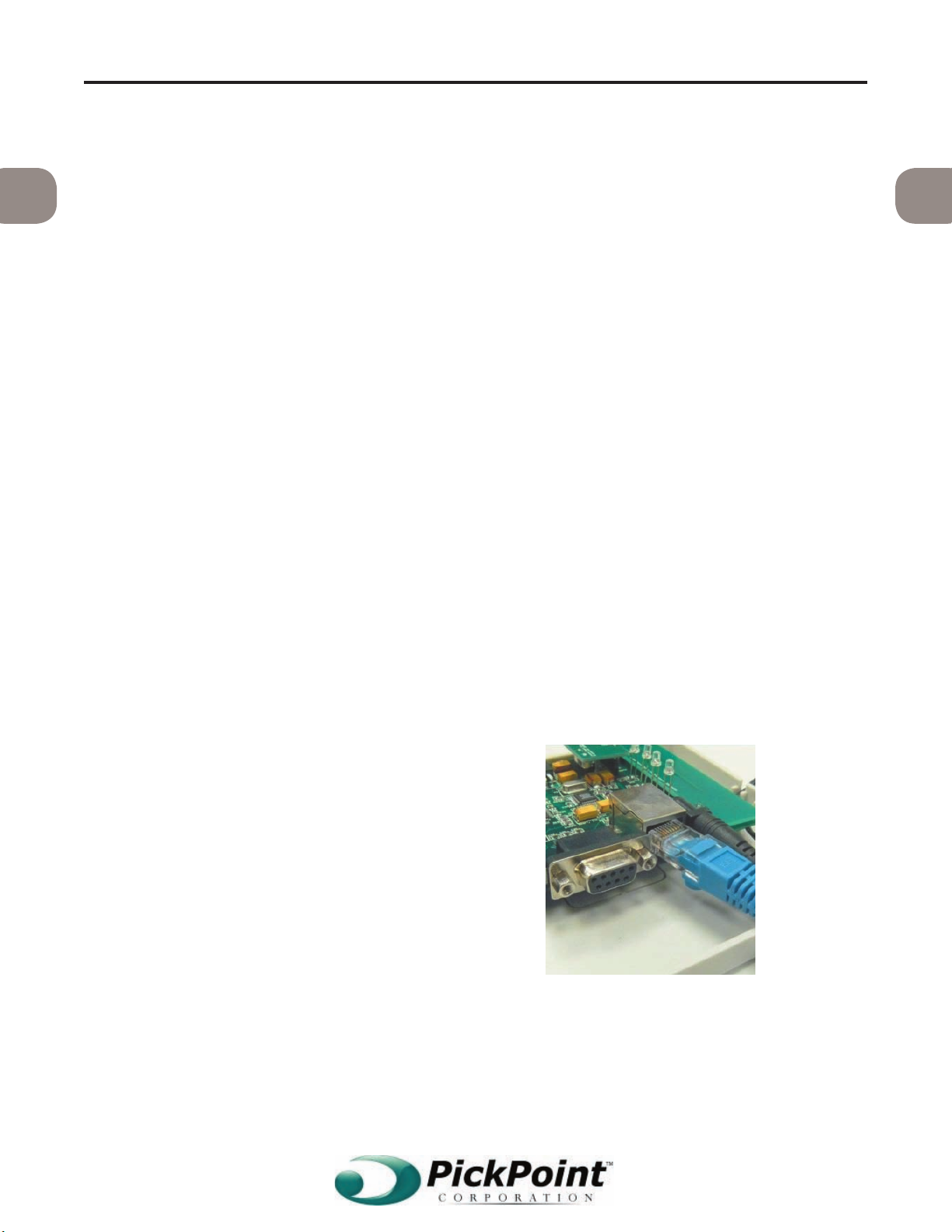
1.2.3.2 Connector
The transceiver uses an RJ45 jack to connect
to the LAN. See Figure 3.
1.2.3.3 Protocol
The transceiver receives data via Ethernet
using the TCP protocol on Port 700.
Figure 3. Transceiver RJ45 jack.
 Loading...