

Page 1

Modification
Sheet
From German Radio Amateur
Jochen Heilemann (DG2IAQ)
© 06.2002 Jochen Heilemann
All rights reserved
Dragon SS-201 Version 1.1
25 - 30 MHz AM/FM/SSB Handheld Transceiver, 4 - 6 Watts
Introduction
The beautiful handheld transceiver came with a very quiet and low modulation. The original FM deviation
was only 1,5 kHz on mine ! With the FM deviation pot on maximum !
Normally you should have a maximum to 2,5 kHz for german cb transmissions or about 5 kHz for amateur
radio use.
Even the modulation sound wasn’t good enough for me. I prefer a loud and clear modulation with a sound
like the original voice.
Also the receiver had to have a more higher sound for recognizing signals in a little loud environments. With
more heights in it, I can better understand poor stations. But that’s your own prefer.
With this modification sheet I had enhanced the transmitting sound, the modulation loudness and the
receiving sound. Only the fm modulation is still a little too dark for me. But I can’t find the fm lowpass filter,
cause the fm part isn’t drawn in the circuit diagram. I only found it in the circuit diagram of the german
version called ALBRECHT AE-201S. But the pcb is difficult at these parts. So with my mod and with original
fm lowpass I get about 2,5 kHz deviation with much more microphone sensitivity.
You mustn’t shout anymore !!!
And with this I mean the original build-in microphone or a external one. You could use preamp mikes of
course, which give even more amplification and loudness. But I would like the handheld to work properly with
the build-in parts cause in some cases you don’t have a preamp mike beside you.
For my mods I only have the circuit diagram of DRAGON SS-201 from:
http://www.mods.dk/mod/other/ss201ed.pdf
and the circuit diagram of ALBRECHT AE-201S form:
http://www.albrecht-online.de/service/Amateurfunk/SS-201/
If someone has a better or more detailed one, maybe with the fm part or with a pcb layout please send it to
me !
- page 1 -
Page 2
Modification
Sheet
From German Radio Amateur
Jochen Heilemann (DG2IAQ)
© 06.2002 Jochen Heilemann
All rights reserved
Dragon SS-201 Version 1.1
25 - 30 MHz AM/FM/SSB Handheld Transceiver, 4 - 6 Watts
General
- page 2 -
Page 3

Modification
Sheet
From German Radio Amateur
Jochen Heilemann (DG2IAQ)
© 06.2002 Jochen Heilemann
All rights reserved
Dragon SS-201 Version 1.1
25 - 30 MHz AM/FM/SSB Handheld Transceiver, 4 - 6 Watts
Transmitter
Position the rig like this. You have to do the changes
on the back of the frontside of the rig.
Unsolder the 4 points of the metal plate and open it to
the top or unsolder all and remove the metal plate.
For the RX mods we have to go to this area.
For the TX mods we have to go to this area.
I removed the electret mike an drilled the mic hole up
to about 3 mm for better an natural sound input. The
original 1 mm hole was to small for my opinion.
Change R472 to 10k –yes, the big one- (more af
output after mic amp. IC412B)
Remove R444 (was parallel fm deviation pot RV401
and reduces the fm modulation)
Change C448 to 68p (the left, brown)
Change R473 to 680k (the right, black)
Gives a higher amplification to the mic amp and
opens its lowpass-filter from 2.8 kHz up to 3.4 kHz).
On mine I only changed C448 yet and let R473 on the
original value of 470k. This works fine. If I think I must
have more preamp gain I will change R473 later.
Change R483 to 10k (the black one)
It’s the internal PTT-Pulldown resistor parallel to the
internal electret mike. This is the reason why the
internal mike is much gentle like a external one.
External mikes mostly have PTT-resistors of approx.
4,7 – 10k. The internal was a 2,2k and reduces mic
sensitivity dramatically.
You maybe also have to change the PTT-Pulldown
resistor of a new external handmike to 10k for
encreasing gain. Some mini-handmikes come also
with only 2,2 – 3,3k.
- page 3 -
Page 4
Modification
Sheet
From German Radio Amateur
Jochen Heilemann (DG2IAQ)
© 06.2002 Jochen Heilemann
All rights reserved
Dragon SS-201 Version 1.1
25 - 30 MHz AM/FM/SSB Handheld Transceiver, 4 - 6 Watts
After this mod I put the fm deviation pot VR401 to the
maximum (I think it was clockwise to the edge, but I’m
not sure. It also can be counter-clockwise.)
On my rig there was another capacitor parallel to
the electret mike and not shown in the circuit
diagram. I removed it and the modulation rised up
significant !
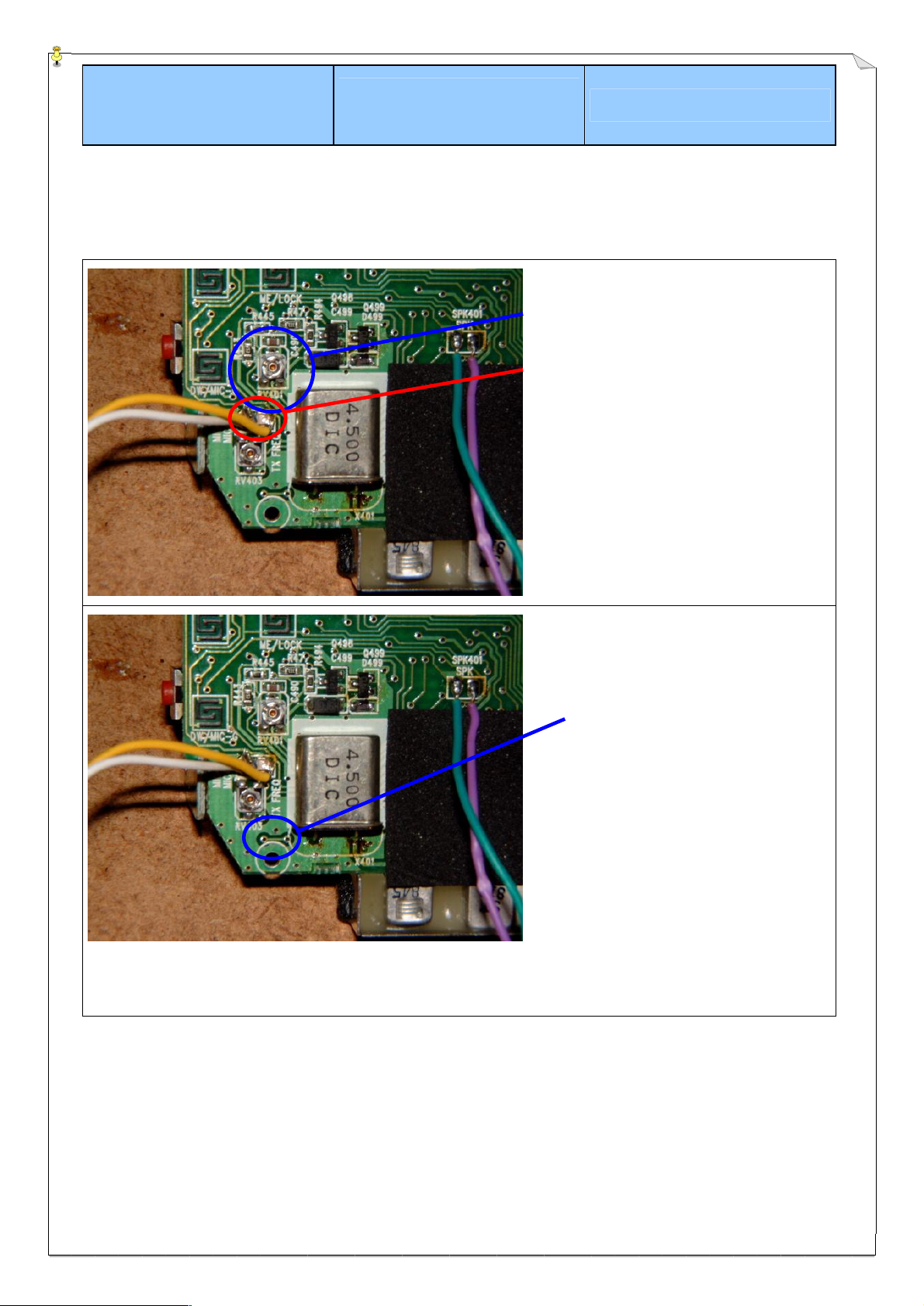
Now I mounted all pcb’s and switch the rig on. I go on
FM and send to a dummy load.
· Center clarifier
· Put a DC meter to this short pcb line
(= measure point)
On receiving you should readout a voltage
of about 1,68 V. The exactly voltage
doesn’t matter, but the clarifier has to be in
the middle position to get the correct
receive voltage.
· Now transmit while recognizing the DC
meter. Adjust RV403 for the same
voltage as in receiving mode. Change
between tx and rx a little bit until the
difference is about max 0,2 V. This is a not
critical tolerance.
Now your rig has the same transmit and receiving
frequency and has no offset or leakage (..like some
cheap ssb export radios in germany...). My SS-201
had a tx voltage of 2,15 V with a receive voltage of
1,68 V !!!
Good DX I say with this good conditions, hi...
- page 4 -
Page 5

Modification
Sheet
From German Radio Amateur
Jochen Heilemann (DG2IAQ)
© 06.2002 Jochen Heilemann
All rights reserved
Dragon SS-201 Version 1.1
25 - 30 MHz AM/FM/SSB Handheld Transceiver, 4 - 6 Watts
After we send and receive now on the same
frequency I checked the total frequency.
T6 T7 T8
AM/FM LSB USB
On AM/FM you could readout the tx signal with a
frequency counter. But my SS-201 worked fine.
On USB + LSB I send with the dummy load and heard
the signal in my exactly amateur radio. Therefore I
used headphones. While transmitting I adjusted T8
for best USB and T7 for best LSB signal sound
without bass swing and without chirp. So when the
signal sounds a little bit like FM or AM sound, the
frequency should be right.
I always aligned my rigs with this method and never
had any problems.
But you must have a exactly reference receiver for
this. without a frequency drift or frequency offset.
Replace C26 with a higher value to give the tx smeter a better average readout.
I tried a 100n and it works fine. If you probably use a
1µ the tx s-meter would work as a P.E.P. power meter
on tx. This might be useful for ssb tx readout.
But 100n was the better choice for me.
- page 5 -
Page 6

Modification
Sheet
From German Radio Amateur
Jochen Heilemann (DG2IAQ)
© 06.2002 Jochen Heilemann
All rights reserved
Dragon SS-201 Version 1.1
25 - 30 MHz AM/FM/SSB Handheld Transceiver, 4 - 6 Watts
Receiver
Remove C407 or change it to 1,2n.
This gives more heights. Af lowpass with original
about max. 500 Hz, after mod at about 2,8 kHz.
Receiving signal is much clearer and louder on all
modes but the fm noise doesn’t raise to much cause
of another af lowpass for fm IF amp.
Solder a 1n – 1,5n (not critical) capacitor between the
both ends of the VOL pot. That means parallel to the
vol pot.
This will also reduce noise over about 3 kHz and
improves the signal noise ratio.
- page 6 -
Page 7

Modification
Sheet
From German Radio Amateur
Jochen Heilemann (DG2IAQ)
© 06.2002 Jochen Heilemann
All rights reserved
Dragon SS-201 Version 1.1
25 - 30 MHz AM/FM/SSB Handheld Transceiver, 4 - 6 Watts
I only had a 1,8n and it works fine.
Now it’s time to also give the rx s-meter a better
average readout.
Locate the three pins of the rx s-meter.
Solder a 100n capacitor from the right (middle) pin to
ground.
So the capacitor is between the cathode of diode D10
and RV1 to ground.
You also can do little experiments by using higher
values. This would give the rx s-meter also some
P.E.P. readout.
But 100n was o.k. for me and the receiving signals
now give more exactly readouts.
- page 7 -
Page 8

Modification
Sheet
From German Radio Amateur
Jochen Heilemann (DG2IAQ)
© 06.2002 Jochen Heilemann
All rights reserved
Dragon SS-201 Version 1.1
25 - 30 MHz AM/FM/SSB Handheld Transceiver, 4 - 6 Watts
I solder a small ceramic type.
For ground connection I used the last pin of the left
pcb (4 pins, the lowest pin has ground contact, you
see it on the pcb)
- page 8 -
Page 9

Modification
Sheet
From German Radio Amateur
Jochen Heilemann (DG2IAQ)
© 06.2002 Jochen Heilemann
All rights reserved
Dragon SS-201 Version 1.1
25 - 30 MHz AM/FM/SSB Handheld Transceiver, 4 - 6 Watts
Alignment
RV1 RX Meter
RV2 Squelch
RV3 TX Meter
RV4 SSB ALC
RV5 AMC (AM Mod)
RV401 FM Deviation
RV403 TX/RX frequency offset must be „0“
T6 AM/FM Carrier
T7 LSB Carrier
T8 USB Carrier
For further informations have a look at
http://members.tripod.com/Malzev/cbrn/ss201.htm
- page 9 -
Page 10

Modification
Sheet
From German Radio Amateur
Jochen Heilemann (DG2IAQ)
© 06.2002 Jochen Heilemann
All rights reserved
Dragon SS-201 Version 1.1
25 - 30 MHz AM/FM/SSB Handheld Transceiver, 4 - 6 Watts
Document History
Version 1.0 10.06.2002 my first hands-on experience
Version 1.1 12.06.2002 open mike hole to 3 mm
tx s-meter average readout
rx s-meter average readout
1,8n parallel vol pot
new „remarks“ page at end of document
- page 10 -
Page 11

Modification
Sheet
From German Radio Amateur
Jochen Heilemann (DG2IAQ)
© 06.2002 Jochen Heilemann
All rights reserved
Dragon SS-201 Version 1.1
25 - 30 MHz AM/FM/SSB Handheld Transceiver, 4 - 6 Watts
Disclaimer · Disclaimer of liability
This modifications mostly need to be done by a electronic profi who had enough practise and who has knowledge in SMD soldering.
You do the modifications on your own risk !
Radio modifications shown here are provided for properly licensed operators only!
The user is solely responsible for making sure that any modifications made to the radio unit must meet all Federal and State
Regulations or the Country of use! Liability of damages to any equipment is the sole responsibility of the user! Downloading , viewing, or
using any information provided on these pages automatically accepts the user to the terms of this agreement! Modifications are
provided for information purposes only!
Although the greatest care has been taken while compiling these documents, we cannot guarantee that the instructions will work on
every radio presented.
Copyright
The author intended not to use any copyrighted material for the publication or, if not possible, to indicate the copyright of the respective
object.
The copyright for any material created by the author is reserved. Any duplication or use of objects such as diagrams, sounds or texts in
other electronic or printed publications is not permitted without the author's agreement.
Some circuit details are passwort-protected because of legal reasons. Please contact me via e-mail.
If your company would like to provide technical information to be featured on this pages please contact me at: dg2iaq@web.de
Jochen Heilemann
P.O. Box 1106
D - 75218 Niefern-Öschelbronn
Germany
e-Mail : DG2IAQ@WEB.DE
Fax : +49 (1212) 5-346-52-897
Callsign : DG2IAQ
DOK : A51 („Die Rassler“)
Locator : JN48JW Latitude 48.917(N) · Longitude 8.783(E)
- page 11 -
Page 12

Modification
Sheet
From German Radio Amateur
Jochen Heilemann (DG2IAQ)
© 06.2002 Jochen Heilemann
All rights reserved
Dragon SS-201 Version 1.1
25 - 30 MHz AM/FM/SSB Handheld Transceiver, 4 - 6 Watts
Remarks
- page 12 -
 Loading...