

Page 1
www.dragino.com
Version
Description
Date
1.0
Release
2019-Dec-8
1.0.1
Improve product photos and network structure
2019-Dec-30
RS485-LN -- RS485 to LoRaWAN Converter User Manual
Document Version: 1.0.1
Image Version: v1.0
RS485 to LoRaWAN Converter User Manual 1 / 29
Page 2

www.dragino.com
1. Introduction .............................................................................................................................. 4
1.1 What is RS485-LN RS485 to LoRaWAN Converter ...................................................................... 4
1.2 Specifications .............................................................................................................................. 5
1.3 Features ...................................................................................................................................... 5
1.4 Applications ................................................................................................................................ 6
1.5 Firmware Change log ................................................................................................................. 7
2. Power ON Device ...................................................................................................................... 7
3. Operation Mode ....................................................................................................................... 8
3.1 How it works? ............................................................................................................................. 8
3.2 Example to join LoRaWAN network ............................................................................................ 8
3.3 Configure Commands to read data .......................................................................................... 11
3.4 Uplink Payload .......................................................................................................................... 14
3.5 Downlink Payload (control RS485 device) ................................................................................ 14
3.6 Buttons ..................................................................................................................................... 17
4. Use AT Command .................................................................................................................... 18
4.1 Access AT Command ................................................................................................................. 18
4.2 Common AT Command Sequence ............................................................................................. 20
4.2.1 Multi-channel ABP mode (Use with SX1301/LG308) ...................................................... 20
4.2.2 Single-channel ABP mode (Use with LG01/LG02) ........................................................... 20
5. FAQ ......................................................................................................................................... 20
5.1 How to upgrade the image? ..................................................................................................... 20
5.2 How to change the LoRa Frequency Bands/Region? ................................................................ 23
5.3 How to set up RS485-LN to work in other 8 channel mode in US915, AU915, CN470 bands? . 24
5.4 How to set up RS485-LN to work with Single Channel Gateway such as LG01/LG02? ............. 25
6. Trouble Shooting ..................................................................................................................... 27
6.1 Downlink doesn’t work, how to solve it? .................................................................................. 27
6.2 Why I can’t join TTN in US915 /AU915 bands? ......................................................................... 27
7. Order Info ............................................................................................................................... 27
RS485 to LoRaWAN Converter User Manual 2 / 29
Page 3

www.dragino.com
8. Packing Info ............................................................................................................................ 27
9. Support ................................................................................................................................... 28
10. Reference ................................................................................................................................ 29
RS485 to LoRaWAN Converter User Manual 3 / 29
Page 4
www.dragino.com
1. Introduction
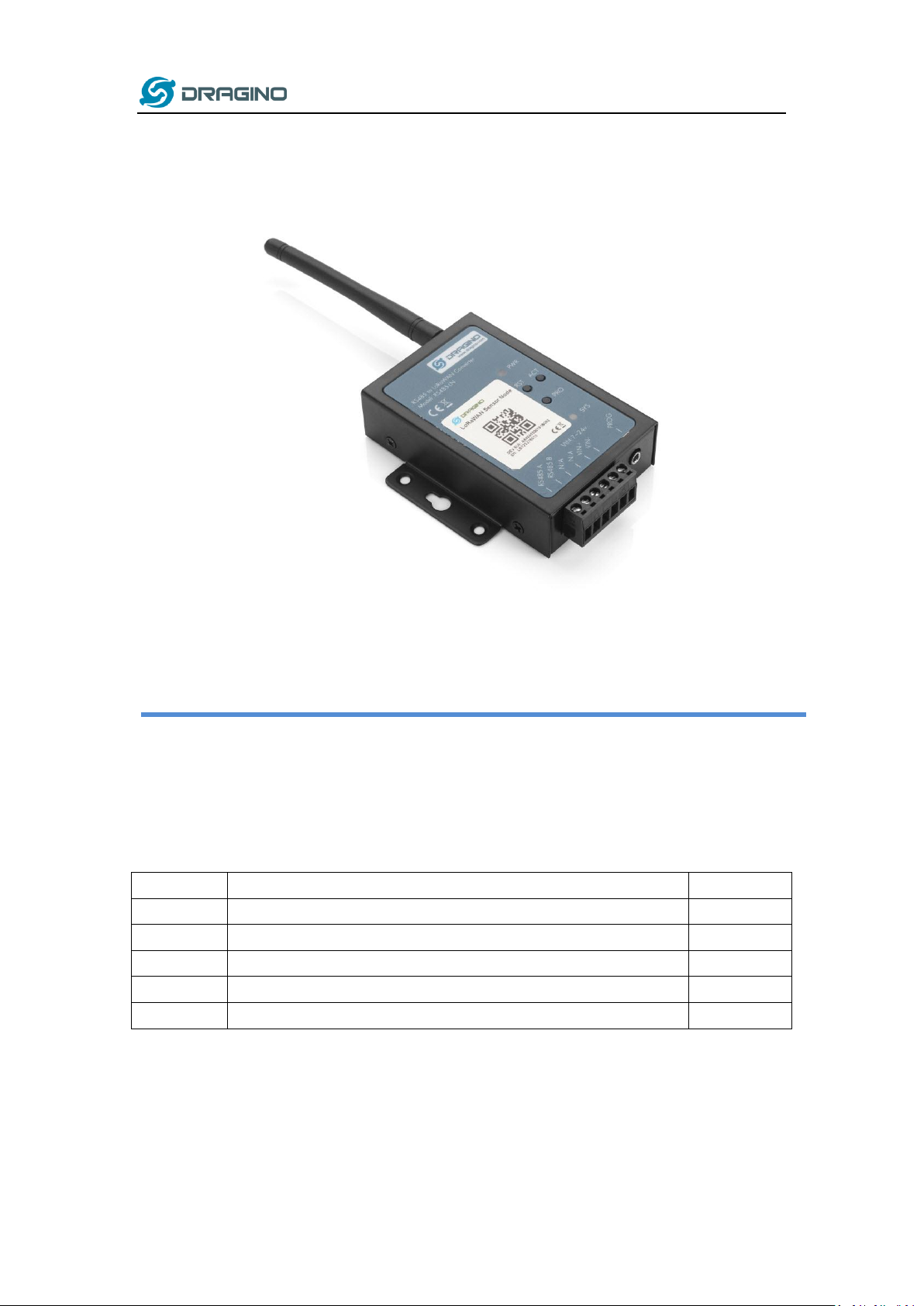
1.1 What is RS485-LN RS485 to LoRaWAN Converter
The Dragino RS485-LN is a RS485 to LoRaWAN Converter. It converts the RS485 signal into
LoRaWAN wireless signal which simplify the IoT installation and reduce the
installation/maintaining cost.
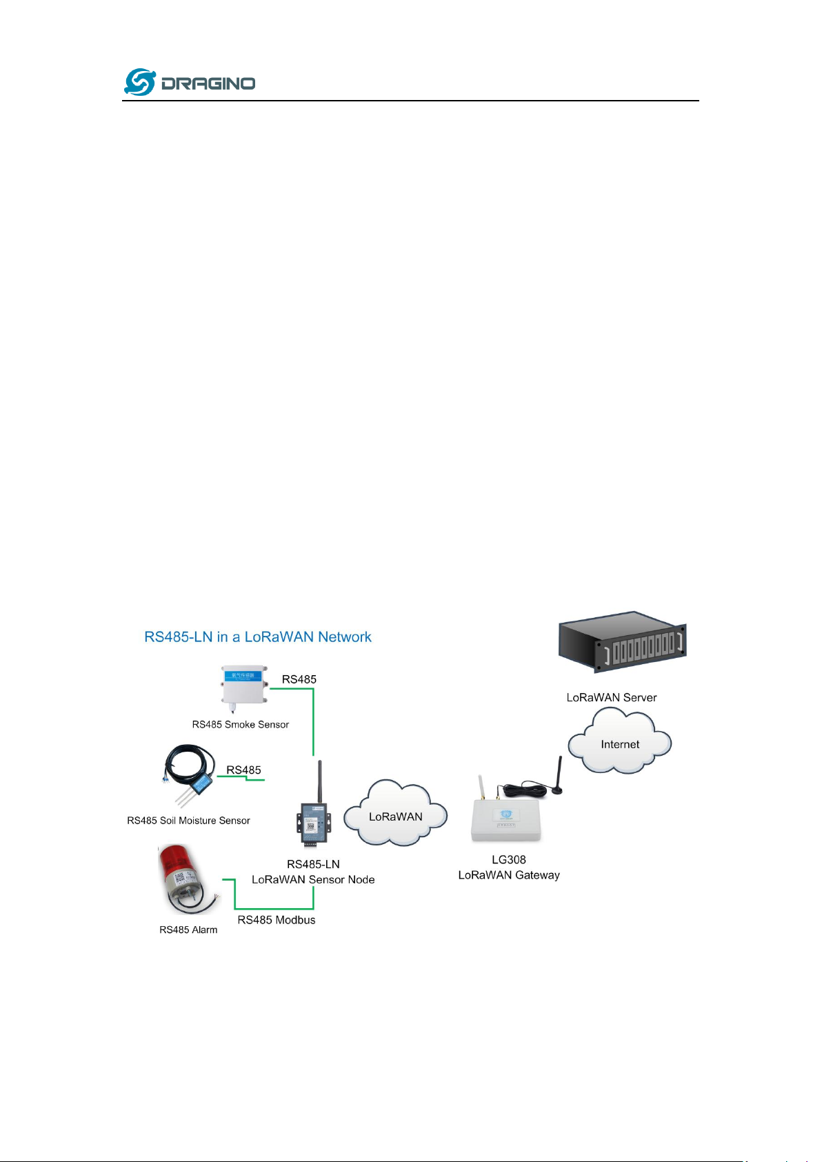
RS485-LN allows user to monitor / control RS485 devices and reach extremely long ranges. It
provides ultra-long range spread spectrum communication and high interference immunity whilst
minimizing current consumption. It targets professional wireless sensor network applications
such as irrigation systems, smart metering, smart cities, smartphone detection, building
automation, and so on.
For data uplink, RS485-LN sends user-defined commands to RS485 devices and gets the return
from the RS485 devices. RS485-LN will process these returns according to user-define rules to get
the final payload and upload to LoRaWAN server.
For data downlink, RS485-LN runs in LoRaWAN Class C. When there downlink commands from
LoRaWAN server, RS485-LN will forward the commands from LoRaWAN server to RS485 devices.
RS485 to LoRaWAN Converter User Manual 4 / 29
Page 5

1.2 Specifications
Hardware System:
STM32L072CZT6 MCU
SX1276/78 Wireless Chip
Power Consumption (exclude RS485 device):
Idle: 32mA@12v
20dB Transmit: 65mA@12v
Interface for Model:
RS485
Power Input 7~ 24V DC.
LoRa Spec:
Frequency Range:
Band 1 (HF): 862 ~ 1020 Mhz
Band 2 (LF): 410 ~ 528 Mhz
168 dB maximum link budget.
+20 dBm - 100 mW constant RF output vs.
+14 dBm high efficiency PA.
Programmable bit rate up to 300 kbps.
High sensitivity: down to -148 dBm.
Bullet-proof front end: IIP3 = -12.5 dBm.
Excellent blocking immunity.
Low RX current of 10.3 mA, 200 nA register retention.
Fully integrated synthesizer with a resolution of 61 Hz.
FSK, GFSK, MSK, GMSK, LoRaTM and OOK modulation.
Built-in bit synchronizer for clock recovery.
Preamble detection.
127 dB Dynamic Range RSSI.
Automatic RF Sense and CAD with ultra-fast AFC.
Packet engine up to 256 bytes with CRC.
www.dragino.com
1.3 Features
LoRaWAN Class A & Class C protocol (default Class C)
Frequency Bands: CN470/EU433/KR920/US915/EU868/AS923/AU915/IN865/RU864
AT Commands to change parameters
Remote configure parameters via LoRa Downlink
Firmware upgradable via program port
Support multiply RS485 devices by flexible rules
Support Modbus protocol
RS485 to LoRaWAN Converter User Manual 5 / 29
Page 6

www.dragino.com
1.4 Applications
Smart Buildings & Home Automation
Logistics and Supply Chain Management
Smart Metering
Smart Agriculture
Smart Cities
Smart Factory
RS485 to LoRaWAN Converter User Manual 6 / 29
Page 7
www.dragino.com
1.5 Firmware Change log
RS485-LN Image files – Download link
Image v1.0
Release
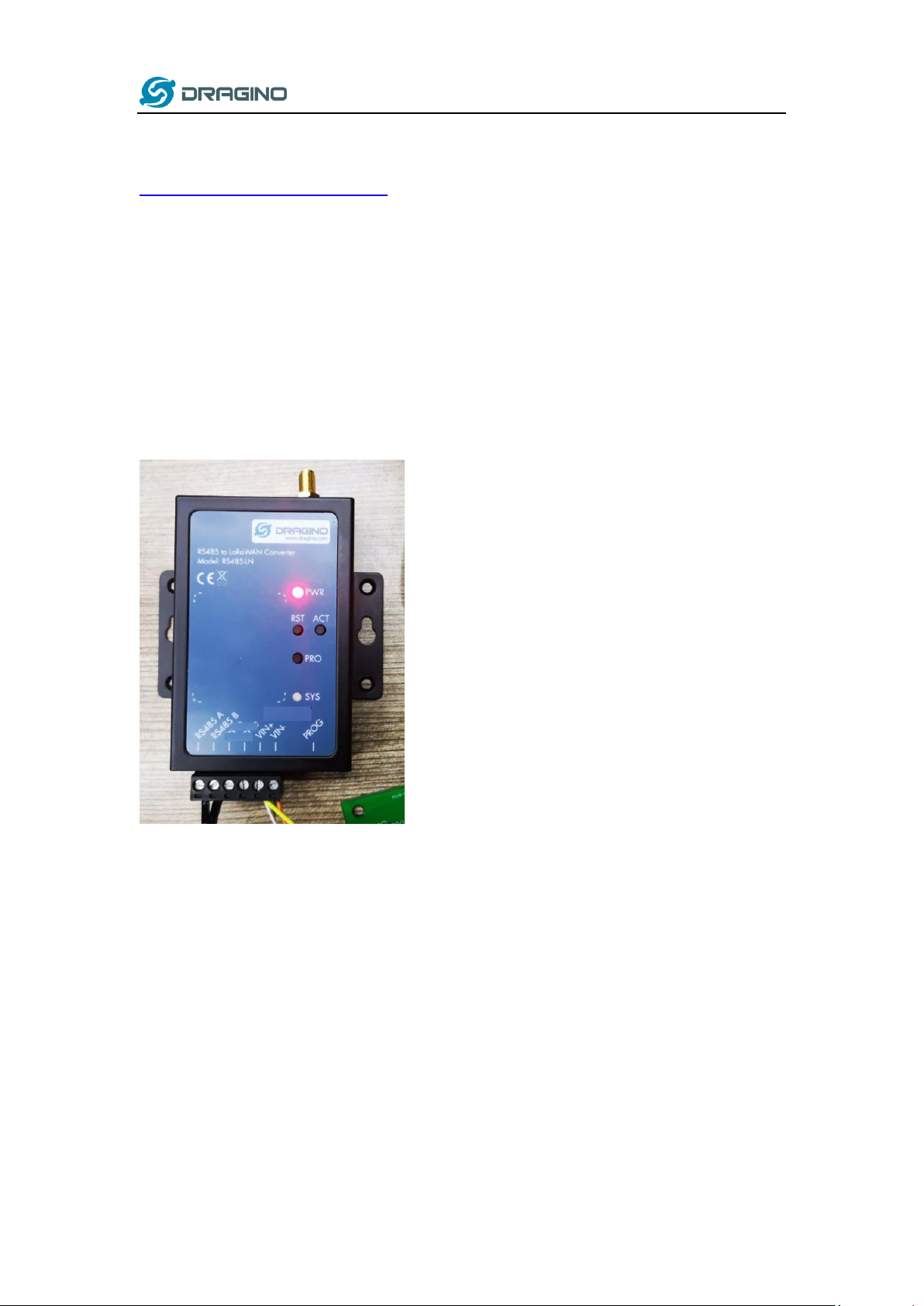
2. Power ON Device
The RS485-LN can be powered by 7 ~ 24V DC power source. Connection as below
Power Source VIN to RS485-LN VIN+
Power Source GND to RS485-LN VIN-
Once there is power, the RS485-LN will be on.
RS485 to LoRaWAN Converter User Manual 7 / 29
Page 8
www.dragino.com
3. Operation Mode
3.1 How it works?
The RS485-LN is configured as LoRaWAN OTAA Class C mode by default. It has OTAA keys to join
network. To connect a local LoRaWAN network, user just need to input the OTAA keys in the
network server and power on the RS485-LN. It will auto join the network via OTAA.
In case user can’t set the OTAA keys in the network server and has to use the existing keys from
server. User can use AT Command to set the keys in the devices.
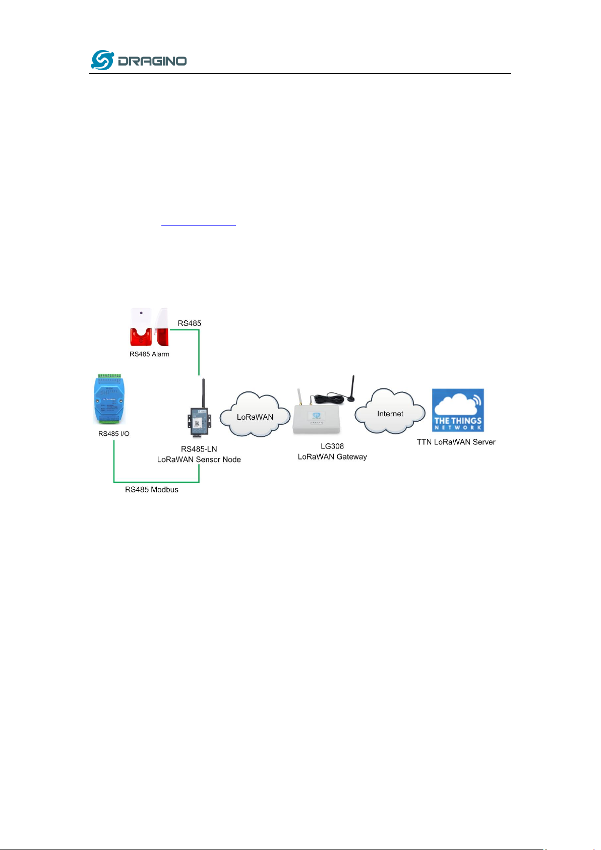
3.2 Example to join LoRaWAN network
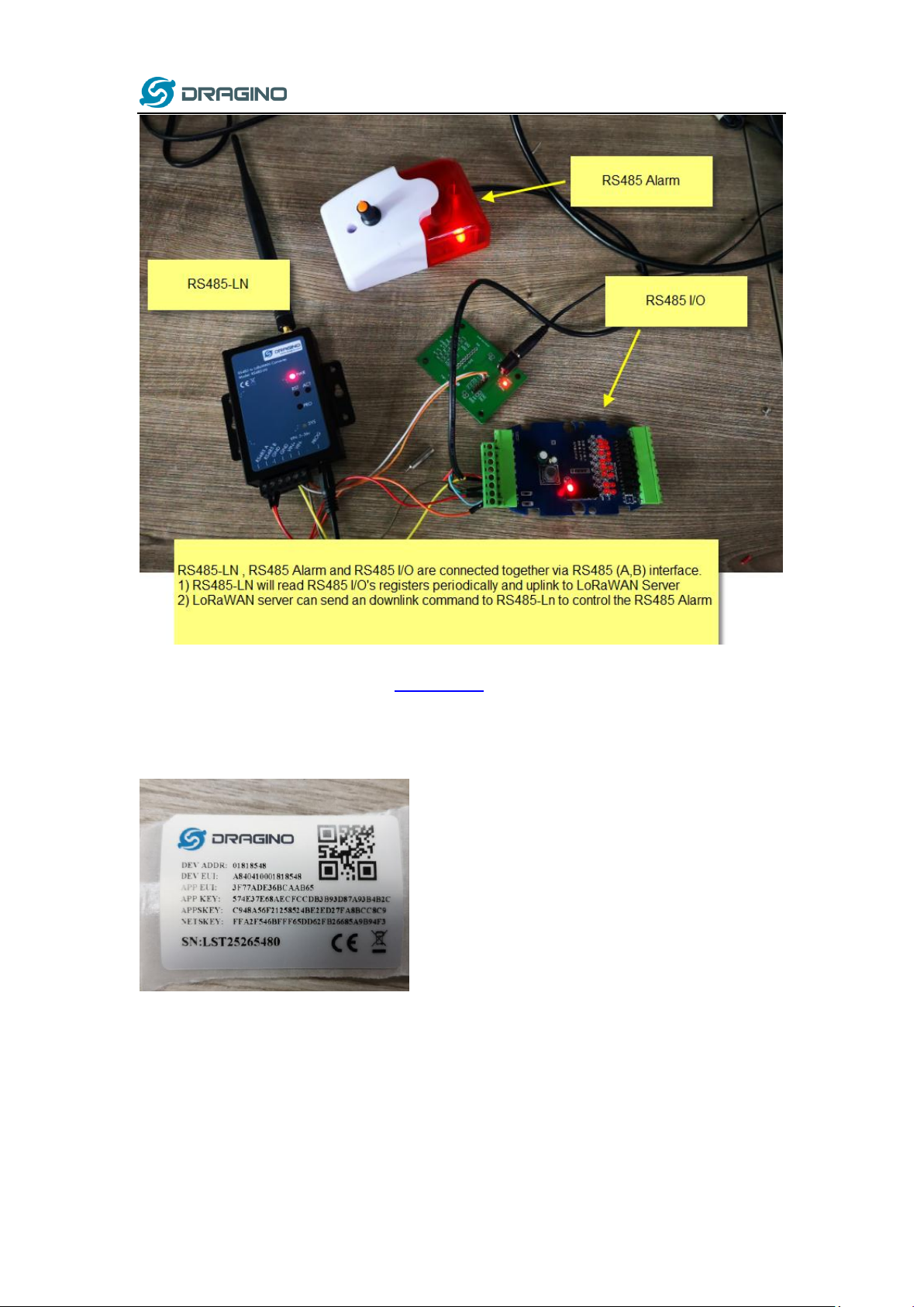
Here shows an example for how to join the TTN Network. Below is the network structure, we use
our LG308 as LoRaWAN gateway here.
The RS485-LN in this example connected to two RS485 devices for demonstration, user can
connect to other RS485 devices via the same method. The connection is as below:
RS485 to LoRaWAN Converter User Manual 8 / 29
Page 9
www.dragino.com
The LG308 is already set to connect to TTN network . So what we need to now is only configure
the TTN:
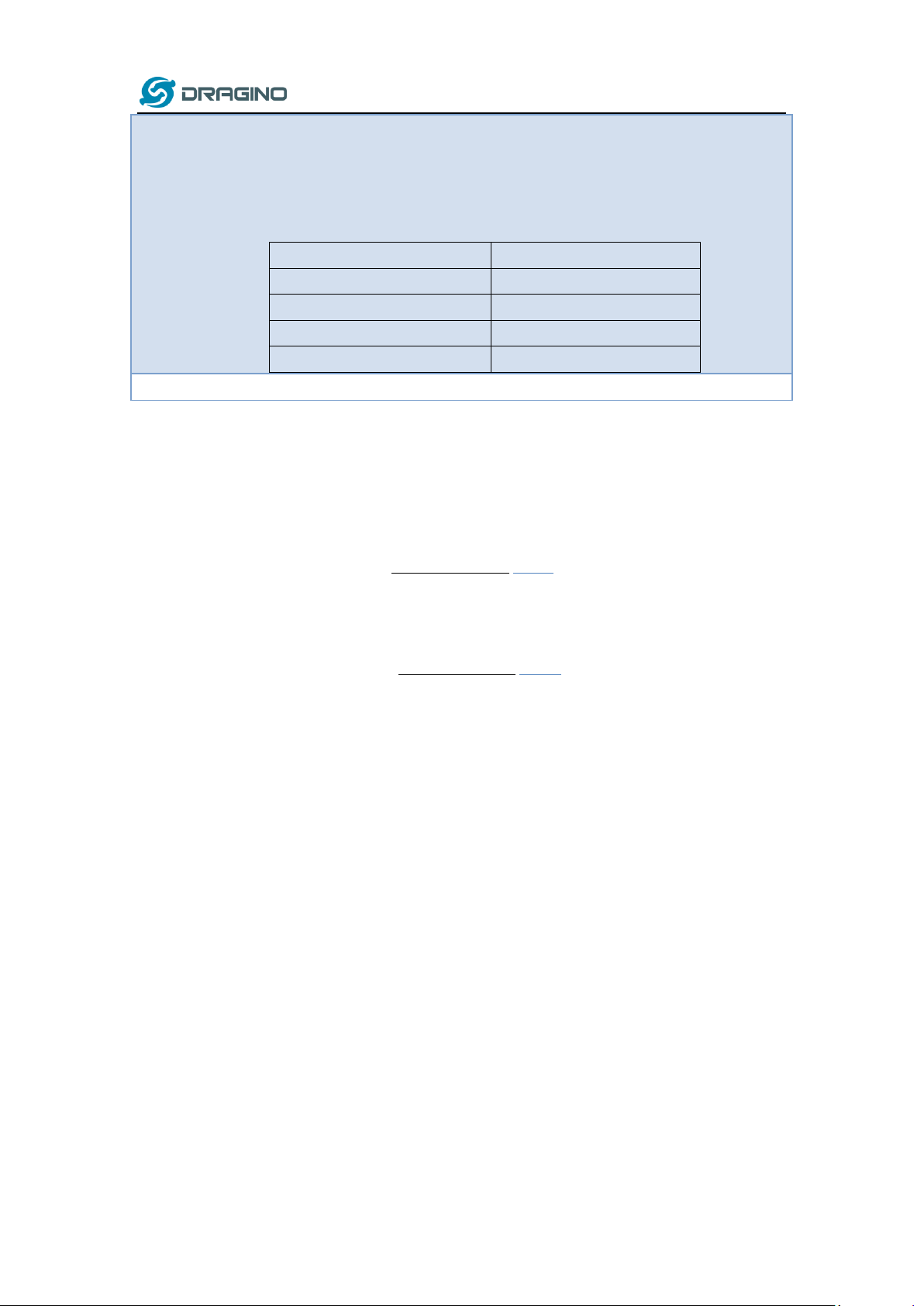
Step 1: Create a device in TTN with the OTAA keys from RS485-LN.
Each RS485-LN is shipped with a sticker with unique device EUI:
RS485 to LoRaWAN Converter User Manual 9 / 29
Page 10

www.dragino.com
User can enter this key in their LoRaWAN Server portal. Below is TTN screen shot:
Add APP EUI in the application.
Add APP KEY and DEV EUI
Step 2: Power on RS485-LN and it will auto join to the TTN network. After join success, it will start
to upload message to TTN and user can see in the panel.
RS485 to LoRaWAN Converter User Manual 10 / 29
Page 11

www.dragino.com
AT Commands
Description
Example
AT+BAUDR
Set the baud rate to communicate with RS485
device. Default Value is: 9600.
AT+BAUDR=9600
Options:
(1200,2400,4800,14400,19200,115200)
AT +CFGDEV
This command is used to configure the RS485
devices; they won’t be used during sampling.
AT+CFGDEV=xx xx xx xx xx xx xx xx xx xx xx xx,m
m: 0: no CRC, 1: add CRC-16/MODBUS in the
end of this command
AT+CFGDEV=xx xx xx xx xx xx xx xx xx xx
xx xx,m
AT+COMMAND1
This command will be sent to RS485 devices
during each sampling.
AT+COMMAND1=xx xx xx xx xx xx xx xx xx xx xx
xx,m
m: 0: no CRC, 1: add CRC-16/MODBUS in the
end of this command
AT+DATACUT1
Get valid data from COMMAND1 return
AT+DATACUT1=a,b,c:
a: total length of return string.
b: start position for valid string.
c: stop position of valid string.
If return1 is:
01 02 01 20 a0 00
AT+DATACUT1=6,4,4 will get the 4th
byte, which is 0x20
AT+COMMAND2
This command will be sent to RS485 devices
during each sampling.
AT+COMMAND2=xx xx xx xx xx xx xx xx xx xx xx
xx,m
m: 0: no CRC, 1: add CRC-16/MODBUS in the
end of this command
AT+DATACUT2
Get valid data from COMMAND2 return
AT+DATACUT2=a,b,c:
a: total length of return string.
b: start position for valid string.
c: stop position of valid string.
If return2 is:
01 01 01 00 a0 00
AT+DATACUT2=6,4,4 will get the 4th
byte, which is 0x20
AT+DATAUP
Connect the result of Command1 and Command2:
AT+DATAUP=x[:pre[:suf]], y[:pre[:suf]]
x,y:valid payload from command x,y
pre: Add prefix
3.3 Configure Commands to read data
There are plenty of RS485 devices in the market and each device has different command to read
the valid data. To support these devices in flexible, RS485-LN supports flexible command set.
User can use AT Commands to configure what commands RS485-LN should send for each
sampling and how to handle the output from RS485 devices.
The AT Commands include:
RS485 to LoRaWAN Converter User Manual 11 / 29
Page 12
suf: Add suffix
If valid payload from command 1 is : EF
If valid payload from command 2 is AB
Then, final payload is:
Command
Final Payload for sampling
AT+DATAUP=1,2
EF AB
AT+DATAUP=1:12,2:56
12 EF 56 AB
AT+DATAUP=1:12:34,2:56:78
12 EF 34 56 AB 78
AT+DATAUP=1::34,2::78
EF 34 AB 78
AT+PAYLOAD
Set PAYLOAD version (size: 1 byte)
Command1 and Command2 will auto run before each uplink.
In this example, we use command1 to get the RS485 IO’s DI status, use command2 to get the
RS485 IO’s DO status.
The RS485 I/O we use here use Modbus RTU to communicate.
The command to get DI status is: 01 02 00 40 00 08 78 18. Where 01 02 00 40 00 08 is the
Modbus command to read the register 00 40 where stored the DI status. The 78 18 is the
CRC-16/MODBUS which calculate manually.
And RS485 I/O will return: 01 02 01 20 a0 00, where 20 here is the value for DI status.
The command to get DO status is: 01 01 00 20 00 08 3C 06. Where 01 01 00 20 00 08 is the
Modbus command to read the register 00 20 where stored the DI status. The 3C 06 is the
CRC-16/MODBUS which calculate manually.
And RS485 I/O will return: 01 01 01 00 51 00, where 00 is the value for DO status.
We want to get the DI status & DO status from RS485 IO and upload to LoRaWAN server, we
might have different RS485-LN to connect to different RS485 devices and upload different
payloads, so it will be good to use different Payload Version to tell the LoRaWAN server what
devices we have connected.
Below are the commands we need to set in RS485-LN:
AT+PAYVER=2 // Set Payload version to 2 (0x02)
AT+COMMAND1=01 02 00 40 00 08,1 // Send 01 02 00 40 00 08 to RS485 network, add
CRC-16/MODBUS at the end.
AT+DATACUT1=6,4,4 // get 6 bytes from the return, and choose the 4th byte as the valid
payload for command 1
AT+COMMAND2=01 01 00 20 00 08,1 // Send 01 01 00 20 00 08 to RS485 network, add
CRC-16/MODBUS at the end.
AT+DATACUT2=6,4,4 // get 6 bytes from the return, and choose the 4th byte as the valid payload
for command 2
AT+DATAUP=1,2 // Link valid payload1 and valid payload2.
www.dragino.com
RS485 to LoRaWAN Converter User Manual 12 / 29
Page 13

www.dragino.com
Final Payload to be uplink will be:
PAYVER + CMD1 VALID RETURN + CMD2 VALID RETURN
RS485 to LoRaWAN Converter User Manual 13 / 29
Page 14

www.dragino.com
Size(bytes)
1
Length depends on the return from the commands
Value
PAYLOAD_VER
If the valid payload is too long and exceed the maximum
support payload length in server, server will show payload not
provided in the LoRaWAN server.
Downlink Control Type
Type Code
Downlink payload
size(bytes)
TDC (Transmit Time Interval)
01 4 RESET
04
2
Poll a uplink
08
2
RS485 control command (Same as AT+CFGDEV)
A8
Not fix
AT+DATAUP=1,2
Example screen shot:
The uplink screen shot is:
3.4 Uplink Payload
3.5 Downlink Payload (control RS485 device)
RS485 to LoRaWAN Converter User Manual 14 / 29
Page 15

www.dragino.com
A8 mm xx xx xx xx xx
mm: 1: add CRC-16/MODBUS ; 0: no CRC
xx: The command want to sent
Set Command1 (Same as AT+COMMAND1)
A9 mm xx xx xx xx xx
mm: 1: add CRC-16/MODBUS ; 0: no CRC
xx: The command1 to be sent.
A9
Not fix
Cut command1 (Same as AT+DATACUT1):
AA mm nn kk
mm: total length nn:start kk:end
AA
4
Set Command2 (Same as AT+COMMAND2)
A9 mm xx xx xx xx xx
mm: 1: add CRC-16/MODBUS ; 0: no CRC
xx: The command1 to be sent.
AB
Not fix
Cut command2 (Same as AT+DATACUT2):
AA mm nn kk
mm: total length nn:start kk:end
AC
4
Cat command (Same as AT+DATAUP)
AD mm nn (3 bytes)
AD mm pre suffix nn prefix suffix (7 bytes)
mm:command number nn:command number
AD
3 or 7
PAYLOAD_VER (Same as AT+PAYVER)
AE kk
KK:version
AE
2
If the payload=0100003C, means to control the END Node’s TDC to 0x00003C=60(S), while type
code is 01.
Example Downlink payload setting in TTN:
Type Code 0x04
If payload = 0x04FF, it will reset the RS485-LN.
Type Code 0x08
If payload = 0x08FF, RS485-LN will immediately send an uplink.
RS485 to LoRaWAN Converter User Manual 15 / 29
Page 16

www.dragino.com
RS485 to LoRaWAN Converter User Manual 16 / 29
Page 17

www.dragino.com
Button
Feature
ACT
If RS485 joined in network, press this button for more than 1 second,
RS485 will upload a packet, and the SYS LED will give a Blue blink
RST
Reboot RS485
PRO
Use for upload image, see How to Update Image
LEDs
Feature
PWR
Always on if there is power
SYS
After device is powered on, the SYS will fast blink in GREEN for 5
times, means RS485-LN start to join LoRaWAN network. If join
success, SYS will be on GREEN for 5 seconds. SYS will blink Blue on
every upload and blink Green once receive a downlink message.
Type Code 0xA8
0xA8 downlink command can be used to control the RS485 devices via LoRaWAN.
For example,
The RS485 Alarm we use here use Modbus RTU to communicate.
The command to active alarm is: 0A 05 00 04 00 01 4C B0. Where 0A 05 00 04 00 01 is the
Modbus command to read the register 00 40 where stored the DI status. The 4C B0 is the
CRC-16/MODBUS which calculate manually.
The command to deactivate alarm is: 0A 05 00 04 00 00 8D 70. Where 0A 05 00 04 00 00 is
the Modbus command to read the register 00 40 where stored the DI status. The 8D 70 is
the CRC-16/MODBUS which calculate manually.
So if user want to use downlink command to control to RS485 Alarm, he can use:
A8 01 0A 05 00 04 00 01 : to activate the RS485 Alarm
A8 01 0A 05 00 04 00 00: to deactivate the RS485 Alarm
A8 is type code and 01 means add CRC-16/MODBUS at the end.
3.6 Buttons
3.7 LEDs
RS485 to LoRaWAN Converter User Manual 17 / 29
Page 18

www.dragino.com
4. Use AT Command
4.1 Access AT Command
RS485-LN supports AT Command set. User can use a USB to TTL adapter plus the 3.5mm Program
Cable to connect to RS485-LN to use AT command, as below.
In PC, User needs to set serial tool(such as putty, SecureCRT) baud rate to 9600 to access to
access serial console of RS485-LN. Below is the output for reference:
RS485 to LoRaWAN Converter User Manual 18 / 29
Page 19

www.dragino.com
More detail AT Command manual can be found at AT Command Manual
RS485 to LoRaWAN Converter User Manual 19 / 29
Page 20

www.dragino.com
4.2 Common AT Command Sequence
4.2.1 Multi-channel ABP mode (Use with SX1301/LG308)
If device has not joined network yet:
AT+FDR
AT+NJM=0
ATZ
If device already joined network:
AT+NJM=0
ATZ
4.2.2 Single-channel ABP mode (Use with LG01/LG02)
AT+FDR Reset Parameters to Factory Default, Keys Reserve
AT+NJM=0 Set to ABP mode
AT+ADR=0 Set the Adaptive Data Rate Off
AT+DR=5 Set Data Rate
AT+TDC=60000 Set transmit interval to 60 seconds
AT+CHS=868400000 Set transmit frequency to 868.4Mhz
AT+RX2FQ=868400000 Set RX2Frequency to 868.4Mhz (according to the result from server)
AT+RX2DR=5 Set RX2DR to match the downlink DR from server. see below
AT+DADDR=26 01 1A F1 Set Device Address to 26 01 1A F1, this ID can be found in the LoRa
Server portal.
ATZ Reset MCU
Note:
1. Make sure the device is set to ABP mode in the IoT Server.
2. Make sure the LG01/02 gateway RX frequency is exactly the same as AT+CHS setting.
3. Make sure SF / bandwidth setting in LG01/LG02 match the settings of AT+DR. refer this
link to see what DR means.
4. The command AT+RX2FQ and AT+RX2DR is to let downlink work. to set the correct
parameters, user can check the actually downlink parameters to be used. As below.
Which shows the RX2FQ should use 868400000 and RX2DR should be 5
5. FAQ
5.1 How to upgrade the image?
RS485 to LoRaWAN Converter User Manual 20 / 29
Page 21

www.dragino.com
The RS485-LN LoRaWAN Controller is shipped with a 3.5mm cable, the cable is used to upload
image to RS485-LN to:
Support new features
For bug fix
Change LoRaWAN bands.
Below shows the hardware connection for how to upload an image to RS485-LN:
Step1: Download flash loader.
Step2: Download the LT Image files.
Step3: Open flashloader; choose the correct COM port to update.
Hold down the PRO button and then momentarily press the RST reset button and the SYS led will change from
OFF to ON, While SYS LED is RED ON, it means the RS485-LN is ready to be program.
RS485 to LoRaWAN Converter User Manual 21 / 29
Page 22

www.dragino.com
Board detected
HOLD PRO then press the
ON, then click next
RST button, SYS will be
RS485 to LoRaWAN Converter User Manual 22 / 29
Page 23

www.dragino.com
Notice: In case user has lost the program cable. User can hand made one from a 3.5mm cable.
The pin mapping is:
5.2 How to change the LoRa Frequency Bands/Region?
User can follow the introduction for how to upgrade image. When download the images, choose
the required image file for download.
RS485 to LoRaWAN Converter User Manual 23 / 29
Page 24

www.dragino.com
CHE
US915 Uplink Channels(125KHz,4/5,Unit:MHz,CHS=0)
0
ENABLE Channel 0-63
1
902.3
902.5
902.7
902.9
903.1
903.3
903.5
903.7
Channel 0-7
2
903.9
904.1
904.3
904.5
904.7
904.9
905.1
905.3
Channel 8-15
3
905.5
905.7
905.9
906.1
906.3
906.5
906.7
906.9
Channel 16-23
4
907.1
907.3
907.5
907.7
907.9
908.1
908.3
908.5
Channel 24-31
5
908.7
908.9
909.1
909.3
909.5
909.7
909.9
910.1
Channel 32-39
6
910.3
910.5
910.7
910.9
911.1
911.3
911.5
911.7
Channel 40-47
7
911.9
912.1
912.3
912.5
912.7
912.9
913.1
913.3
Channel 48-55
8
913.5
913.7
913.9
914.1
914.3
914.5
914.7
914.9
Channel 56-63
Channels(500KHz,4/5,Unit:MHz,CHS=0)
903
904.6
906.2
907.8
909.4
911
912.6
914.2
Channel 64-71
5.3 How to set up RS485-LN to work in other 8 channel mode in US915, AU915,
CN470 bands?
By default, the frequency bands US915, AU915, CN470 works in 8~15 (CHE=2) frequencies. User
can set to the frequencies to work in other channels, by using the AT+CHE command.
For example, in US915 band, the frequency table is as below. By default, end node will use all
channels (8~15) for OTAA Join process. After OTAA JOINED, end node will use these channels
(8~15) to send uplink packets.
When user uses the TTN network, the US915 frequency bands use are:
903.9 - SF7BW125 to SF10BW125
904.1 - SF7BW125 to SF10BW125
904.3 - SF7BW125 to SF10BW125
904.5 - SF7BW125 to SF10BW125
904.7 - SF7BW125 to SF10BW125
904.9 - SF7BW125 to SF10BW125
905.1 - SF7BW125 to SF10BW125
905.3 - SF7BW125 to SF10BW125
904.6 - SF8BW500
If user want to hopping is all channels. , user can access the device via AT Command and run:
AT+CHE=0
ATZ
to set the end node to work in all 72 channel mode.
RS485 to LoRaWAN Converter User Manual 24 / 29
Page 25

www.dragino.com
CHE
AU915 Uplink Channels(125KHz,4/5,Unit:MHz,CHS=0)
0
ENABLE Channel 0-63
1
915.2
915.4
915.6
915.8
916
916.2
916.4
916.6
Channel 0-7
2
916.8
917
917.2
917.4
917.6
917.8
918
918.2
Channel 8-15
3
918.4
918.6
918.8
919
919.2
919.4
919.6
919.8
Channel 16-23
4
920
920.2
920.4
920.6
920.8
921
921.2
921.4
Channel 24-31
5
921.6
921.8
922
922.2
922.4
922.6
922.8
923
Channel 32-39
6
923.2
923.4
923.6
923.8
924
924.2
924.4
924.6
Channel 40-47
7
924.8
925
925.2
925.4
925.6
925.8
926
926.2
Channel 48-55
8
926.4
926.6
926.8
927
927.2
927.4
927.6
927.8
Channel 56-63
Channels(500KHz,4/5,Unit:MHz,CHS=0)
915.9
917.5
919.1
920.7
922.3
923.9
925.5
927.1
Channel 64-71
AU915 is similar. Below is the AU915 Uplink Channels.
5.4 How to set up RS485-LN to work with Single Channel Gateway such as
LG01/LG02?
In this case, users need to set RS485-LN to work in ABP mode & transmit in only one frequency.
Assume we have a LG02 working in the frequency 868400000 now , below is the step.
Step1: Log in TTN, Create an ABP device in the application and input the network session key
(NETSKEY), app session key (APPSKEY) from the device.
Note: user just need to make sure above three keys match, User can change either in TTN or Device to make then
match. In TTN, NETSKEY and APPSKEY can be configured by user in setting page, but Device Addr is generated by
TTN.
RS485 to LoRaWAN Converter User Manual 25 / 29
Page 26

www.dragino.com
Step2: Run AT Command to make LT work in Single frequency & ABP mode. Below is the AT
commands:
AT+FDR Reset Parameters to Factory Default, Keys Reserve
AT+NJM=0 Set to ABP mode
AT+ADR=0 Set the Adaptive Data Rate Off
AT+DR=5 Set Data Rate (Set AT+DR=3 for 915 band)
AT+TDC=60000 Set transmit interval to 60 seconds
AT+CHS=868400000 Set transmit frequency to 868.4Mhz
AT+DADDR=26 01 1A F1 Set Device Address to 26 01 1A F1
ATZ Reset MCU
As shown in below:
RS485 to LoRaWAN Converter User Manual 26 / 29
Page 27

www.dragino.com
6. Trouble Shooting
6.1 Downlink doesn’t work, how to solve it?
By default, LT will open two RX windows to get downlink message after uplink. If the server’s
radio parameter is not match with the radio parameters in downlink, the downlink message
won’t arrive. And in UART access to LT, user will see below message:
txDone
rxTimeout
rxTimeout
If user see below output:
txDone
rxDone
rxTimeout
It means the downlink message arrive but not parse. In this case, user need to set FPORT=2 in the
server side for downlink message.
6.2 Why I can’t join TTN in US915 /AU915 bands?
It is about the channels mapping. Please see this link for detail.
7. Order Info
Part Number: RS485-LN-XXX
XXX:
EU433: frequency bands EU433
EU868: frequency bands EU868
KR920: frequency bands KR920
CN470: frequency bands CN470
AS923: frequency bands AS923
AU915: frequency bands AU915
US915: frequency bands US915
IN865: frequency bands IN865
CN779: frequency bands CN779
8. Packing Info
Package Includes:
RS485-LN x 1
Stick Antenna for LoRa RF part x 1
Program cable x 1
RS485 to LoRaWAN Converter User Manual 27 / 29
Page 28

www.dragino.com
Dimension and weight:
Device Size: 13.5 x 7 x 3 cm
Device Weight: 105g
Package Size / pcs : 14.5 x 8 x 5 cm
Weight / pcs : 170g
9. Support
Support is provided Monday to Friday, from 09:00 to 18:00 GMT+8. Due to different
timezones we cannot offer live support. However, your questions will be answered as soon
as possible in the before-mentioned schedule.
Provide as much information as possible regarding your enquiry (product models, accurately
describe your problem and steps to replicate it etc) and send a mail to
support@dragino.com
RS485 to LoRaWAN Converter User Manual 28 / 29
Page 29

www.dragino.com
10. Reference
Product Page
Image Download
AT Command Manual
Hardware Source
RS485 to LoRaWAN Converter User Manual 29 / 29
 Loading...