

Page 1
Technical Service Manual
Fabius GS
Inhalation Anesthesia Machine
Emergency Care • Perioperative Care • Critical Care • Perinatal Care • Home Care
Revision 3.0
5330.500
9036095
Because you care
Page 2

Page 3

Contents
General
1 Notes 3
1.1 Symbols and Definitions ......................................................................................................... 4
Function Description
1 General Information about the Fabius GS 7
2 Function diagram of Fabius GS 12
3 Battery backup 14
4 Fabius GS piping diagram 14
5 Function description of gas box 15
6 SORC (Sensitive Oxygen Ratio Controller) 16
7 Cosy 2 breathing system 18
7.1 Ventilation mode ................................................................................................................... 22
7.2 Function description: Manual ventilation .............................................................................. 23
7.3 Function description: Spontaneous breathing ...................................................................... 27
7.4 Function description: Volume/pressure control ventilation mode ......................................... 31
7.5 Cosy 2 absorber ................................................................................................................... 35
8 Ventilator 35
8.1 Safety valve .......................................................................................................................... 38
8.2 Auxiliary air valve ................................................................................................................. 38
9 Pneumatics 39
9.1 PEEP/Pmax valve control .................................................................................................... 39
9.2 APL bypass valve control ..................................................................................................... 40
All rights reserved. Copyright reserved.
K5330500IECIVZ.fm 10.11.05
I
Page 4

Contents
10 Electrical block diagram 41
11 Function description: Control PCB 41
12 Control panel assembly 42
13 FiO2 Measurement 44
14 Respiratory Flow Measurement 45
15 Gas flow rate measurement 46
16 Anesthetic vaporizer(s) 47
17 Leak test 49
17.1 System leak test ................................................................................................................... 49
17.2 Patient leak test .................................................................................................................... 49
Annex
Parts catalog
Technical Information
All rights reserved. Copyright reserved.
K5330500IECIVZ.fm 10.11.05
II
Page 5

General
1
Page 6

2
Page 7

Fabius GS General
1Notes This Technical Documentation conforms to the IEC 60601-1 standard.
Read each step in every procedure thoroughly before beginning any test.
Always use the proper tools and specified test equipment. If you deviate from
the instructions and/or recommendations in this Technical Documentation,
the equipment may operate improperly or unsafely, or the equipment could
be damaged.
Use only original Dräger parts and supplies.
The maintenance procedures described in this Technical Documentation may
be performed by qualified service personnel only. These maintenance
procedures do not replace inspections and servicing by the manufacturer.
The information in this manual is confidential and may not be disclosed to
third parties without the prior written consent of the manufacturer.
Strictly follow the Instructions for Use manual / Operating
Instructions! This Technical Documentation does not replace the
Instructions for Use manual / Operating Instructions. Any use of the
product requires full understanding and strict observation of the
product-specific Instructions for Use manual/ Operating Instructions.
Reference is hereby made to the observance of the relevant safety
provisions, for example in Germany, the Medical Product Law (MPG), the
Medical Device Operator Ordinance (MPBetreibV), the Pressure Container
Ordinance (Druckbehälterverordnung), the Technical Rules for Pressurized
Gases (Technische Regeln Druckgase), or the Occupational Health and
Safety Provisions (Unfallverhütungsvorschriften).
Unless otherwise stated, reference is made to laws, regulations or
standards (as amended) applicable in the Federal Republic of Germany.
Follow the laws and regulations applicable in your country.
Observe protection mark DIN 34. Copyright reserved.
Version 2.0_ Released_Printed on_10.11.05_K5330500_General.fm
5330.500
3
Page 8

General Fabius GS
1.1 Symbols and
Definitions
This symbol indicates a warning.
This symbol indicates tips and useful information.
This symbol is used to alert against unsafe practices when handling
electrostatic sensitive devices (ESD).
Definitions according to German standard DIN 31051:
Inspection = examination of actual condition
Maintenance = measures to maintain specified condition
Repair = measures to restore specified condition
Servicing = inspection, maintenance, and repair
Version 2.0_ Released_Printed on_10.11.05_K5330500_General.fm
Observe protection mark DIN 34. Copyright reserved.
4
5330.500
Page 9

Function Description
5
Page 10

6
Page 11
Fabius GS Function description
1 General Information
about the Fabius GS
The Fabius GS comprises the following assemblies:
– Display and Control Panel
– Flowmeter assembly
– Gas box: Gas Inlet Assembly and related items
– Breathing system
– Pneumatic assembly
– Ventilator
– Vaporizers
– Trolley
Monitoring, electrical connections and gas connections as shown in Figure 1,
Figure 2, Figure 3, and Figure 4.
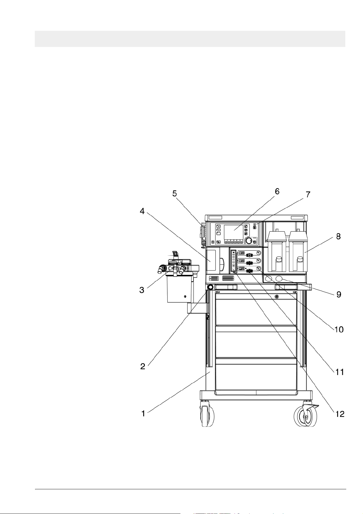
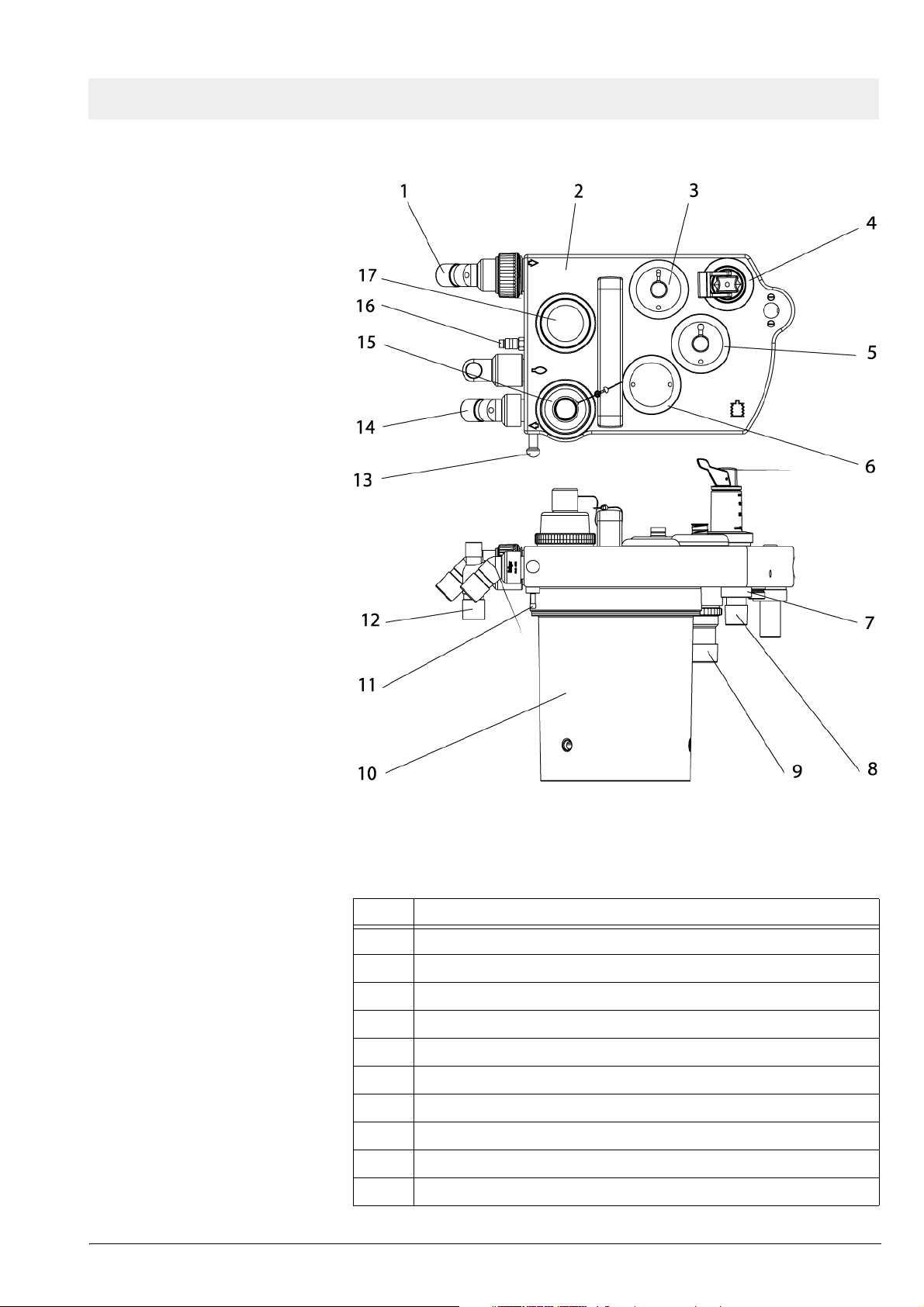
Figure 1 Front view of Fabius GS anesthesia system, for legend see Table
1
All rights reserved. Copyright reserved.
Version 1.0_ Released_Printed on_10.11.05_F5330500_Function_Description.fm
5330.500
7
Page 12

Function description Fabius GS
Table 1 Legend to Figure 1
No. Name
1 Trolley
2 O2 flush
3 Cosy 2 breathing system
4 Ventilator
5 Oxygen flowmeter (auxiliary)
6 Display
7 Control panel
8 Vaporizers
9 Cylinder Pressure Gauges
10 Pipeline Pressure Gauges
11 Flow Control Valves
12 Total fresh gas flowmeter
Version 1.0_ Released_Printed on_10.11.05_F5330500_Function_Description.fm
All rights reserved. Copyright reserved.
8
5330.500
Page 13
Fabius GS Function description
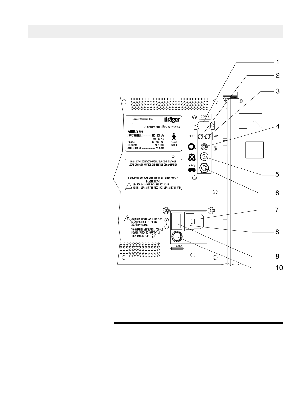
Figure 2 Rear view showing interface panel and power entry, for legend
see Ta b l e 2
Table 2 Legend to Figure 2
No. Name
1 Serial communication ports (only one is shown)
2 Tube connection for PEEP valve
3 Tube connection for APL bypass valve
4 O2 sensor connection
5 Airway pressure connection
6 Spirolog sensor connection
7 Power entry
8 Cover for power fuses (2x 2.5 A)
All rights reserved. Copyright reserved.
Version 1.0_ Released_Printed on_10.11.05_F5330500_Function_Description.fm
5330.500
9
Page 14
Function description Fabius GS
No. Name
9 ON/OFF switch
10 Battery fuse
10
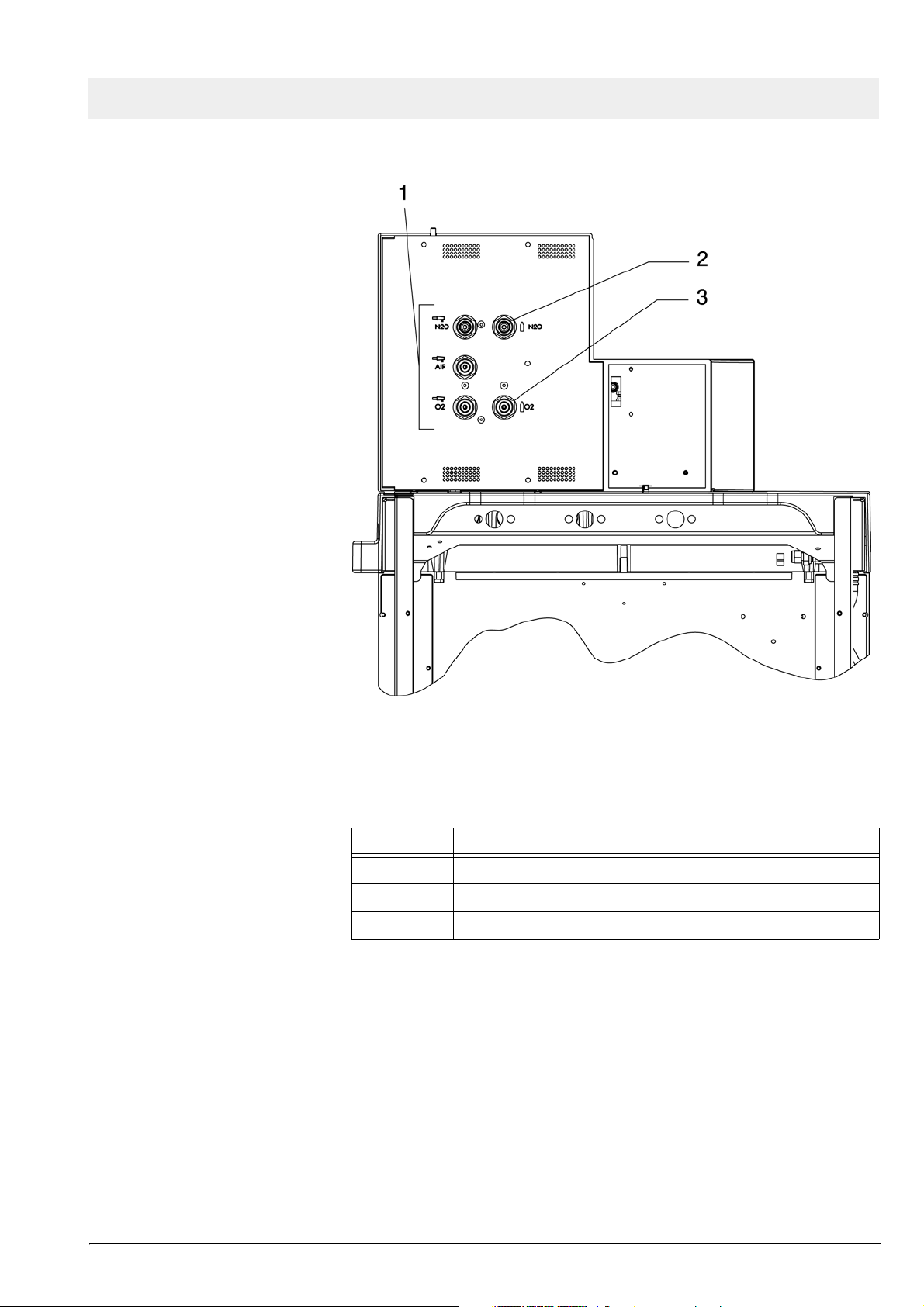
Figure 3 Rear view showing gas pipeline and PIN index cylinder connec-
tions, for legend see Ta b l e 3
Table 3 Legend to Figure 3
No. Name
1 Pipeline tube connections
2 N2O or AIR PIN index cylinder connections
3 O2 PIN index cylinder connection
4 O2 PIN index cylinder connection
5330.500
Version 1.0_ Released_Printed on_10.11.05_F5330500_Function_Description.fm
All rights reserved. Copyright reserved.
Page 15
Fabius GS Function description
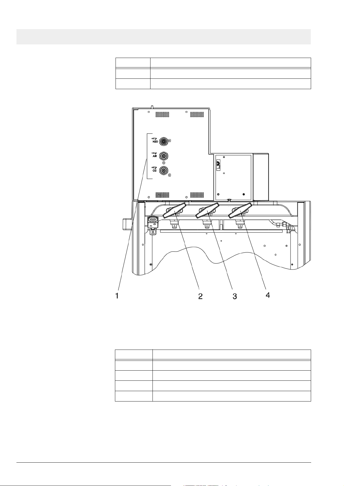
Figure 4 Rear view showing gas pipeline and cylinder connections (units
without PIN index cylinder connections), for legend see Table 4
Table 4 Legend to Figure 4
No. Name
1 Pipeline tube connections
2 N2O cylinder connection
3 O2 cylinder connection
All rights reserved. Copyright reserved.
Version 1.0_ Released_Printed on_10.11.05_F5330500_Function_Description.fm
5330.500
11
Page 16
Function description Fabius GS
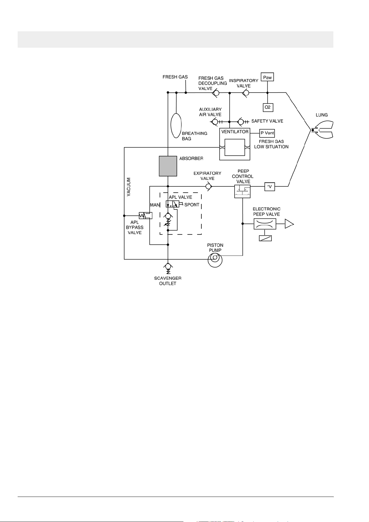
2 Function diagram of
Fabius GS
Figure 5 Function diagram of Fabius GS - Cosy 2 breathing system
12
5330.500
Version 1.0_ Released_Printed on_10.11.05_F5330500_Function_Description.fm
All rights reserved. Copyright reserved.
Page 17
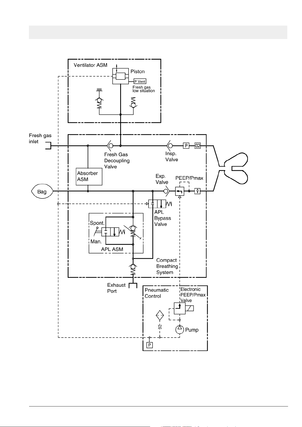
Fabius GS Function description
Figure 6 Function diagram of Fabius GS - Cosy 2.5 (2.6) breathing system
All rights reserved. Copyright reserved.
Version 1.0_ Released_Printed on_10.11.05_F5330500_Function_Description.fm
5330.500
13
Page 18
Function description Fabius GS
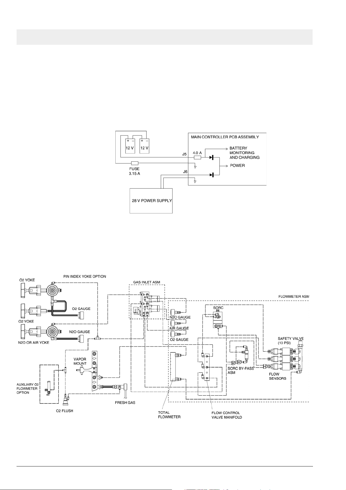
3 Battery backup Fabius GS backup power is provided by two series-connected 12 V recharge-
able batteries. These batteries remain on charge as long as the machine is
plugged into an active AC outlet. Should power supply fail while the machine
is in operation, the batteries will allow the machine to continue operating for a
minimum of 45 minutes, provided that the batteries are fully charged.
The batteries are accessible by opening the ventilator compartment. The
3.15A battery fuse is located at the back of the control box.
4 Fabius GS piping
diagram
Figure 7 Battery backup arrangement
Figure 8 Fabius GS piping diagram
14
5330.500
Version 1.0_ Released_Printed on_10.11.05_F5330500_Function_Description.fm
All rights reserved. Copyright reserved.
Page 19
Fabius GS Function description
5 Function descrip-
tion of gas box
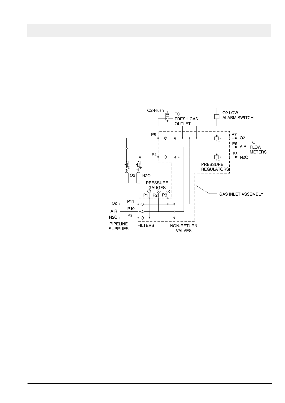
The supply gases flow through the filters and non-return valves in the gas
inlet assembly. Pipeline supply pressures are indicated on pipeline pressure
gauges located on the flowmeter assembly. Cylinder pressure gauges are
located on the trolley assembly. The pressures of O2 and N2O delivered to
the flowmeter assembly are set by regulators on the gas inlet assembly.
Should the O2 supply fail or if its pressure decrease below a certain limit, the
O2 low alarm switch signals an alarm.
Figure 9 Gas box function diagram, part 1
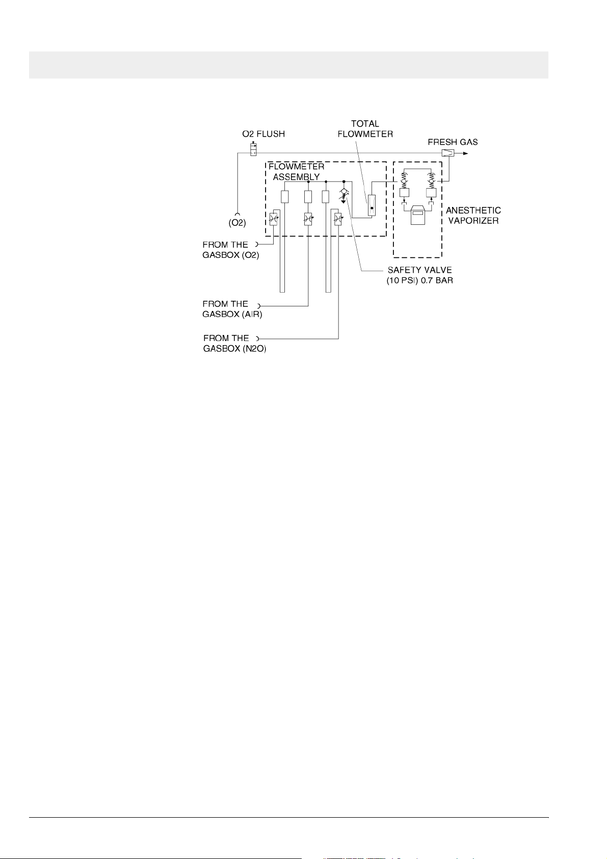
If the O2 flush button is pressed, oxygen is delivered to the fresh-gas outlet.
The fresh-gas ejector prevents the fresh gas from flowing back into the anesthetic vaporizer. This avoids an increase in the anesthetic gas concentration.
All rights reserved. Copyright reserved.
Version 1.0_ Released_Printed on_10.11.05_F5330500_Function_Description.fm
5330.500
15
Page 20
Function description Fabius GS
6 SORC (Sensitive
Oxygen Ratio Controller)
Figure 10 Gas box function diagram, part 2
The SORC is a control element that functions like an N2O shut-off device and
ensures a vital O2 concentration in the fresh gas. In the event of an O2 shortage, the SORC limits the N2O flow such that the O2 concentration in the
fresh gas does not decrease below 21 vol.%.
If the O2 flow control valve is closed or if the O2 flow is lower than or equal to
200 mL/min, the SORC interrupts the N2O flow.
N2O can be added as of an O2 flow of approx. 300 mL/min. In this case, the
SORC also prevents O2 concentrations below 21 vol.%.
The SORC bypass allows O2 to bypass the restrictor in the SORC when O2
flows above 10 L/min are needed.
16
5330.500
Version 1.0_ Released_Printed on_10.11.05_F5330500_Function_Description.fm
All rights reserved. Copyright reserved.
Page 21
Fabius GS Function description
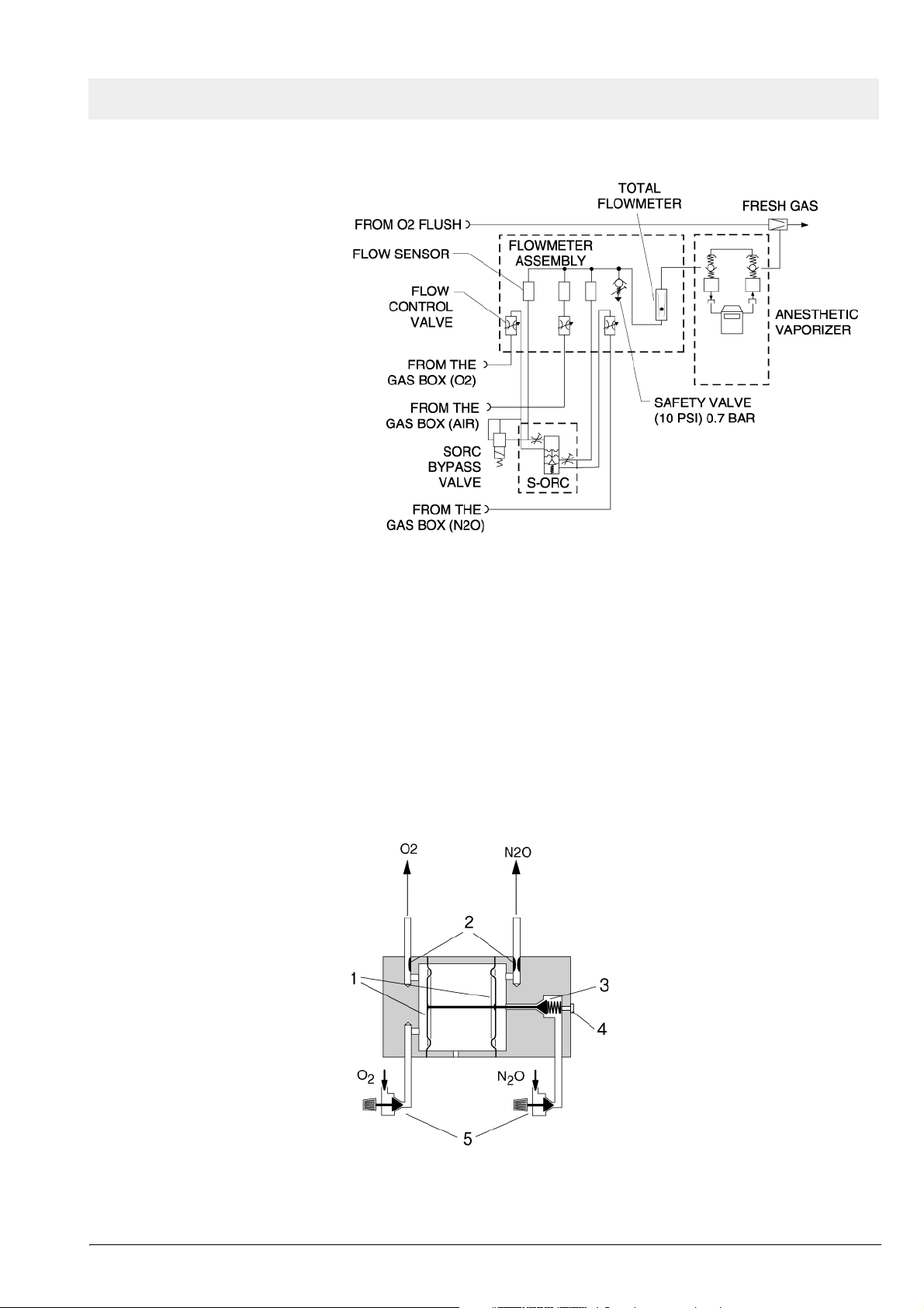
Figure 11 SORC function diagram, part 1
The O2 and N2O flows are adjusted with the flow control valves.
Restrictors located at the outlets of the SORC generate back-pressures.
These back-pressures exert a force on the control diaphragms of the SORC.
The O2 back-pressure opens the SORC. The N2O back-pressure closes the
SORC. The pressure ratio at the control diaphragm affects the N2O flow.
The resistors and the spring force are dimensioned such that a minimum concentration of 21 vol.% of O2 is always ensured. The maximum O2 flow is
approx. 12 L/min.
Figure 12 SORC function diagram, part 2, for legend see Tab le 5
All rights reserved. Copyright reserved.
Version 1.0_ Released_Printed on_10.11.05_F5330500_Function_Description.fm
5330.500
17
Page 22

Function description Fabius GS
Table 5 Legend to Figure 12
No. Name
1 Control diaphragms
2 Restrictors
3 N2O non-return valve
4 Operating-point adjusting screw
5 Flow control valves
7 Cosy 2 breathing
system
The Cosy 2 breathing system allows three modes of patient ventilation:
– Manual ventilation and spontaneous breathing
– Volume controlled ventilation
– Pressure controlled ventilation
The APL valve (adjustable pressure limiting valve), lever type, has a selector
switch which can be used to toggle between “MAN” and “SPONT”.
On APL valves with control knob, switching from “IPPV/SPONT” to “MAN” is
carried out by turning the knob.
In the “MAN” position, the breathing system is closed to atmosphere. This
position is used for manual ventilation of the patient. The APL valve opening
pressure can be adjusted from 5 to 70 cmH2O (mbar).
In the “SPONT” position the APL valve is open to atmosphere. This position
is used for spontaneous breathing.
Using the control box and the PEEP Pmax valve, the pressure limit (Pmax)
can also be adjusted during volume control from 15 cmH2O (mbar) to
70 cmH2O (mbar) via the membrane keypad.
18
5330.500
Version 1.0_ Released_Printed on_10.11.05_F5330500_Function_Description.fm
All rights reserved. Copyright reserved.
Page 23
Fabius GS Function description
Figure 13 Cosy 2 breathing system, for legend see Tabl e 6
Table 6 Legend to Figure 13
No. Name
1 Expiratory connection
2 Flow sensor (Spirolog) (not shown)
3 PEEP/Pmax valve
4 MAN/SPONT APL valve
5 APL Bypass valve
6 Fresh-gas decoupling valve
7 Fresh-gas port
8 Ventilator port
9 Anesthetic gas scavenging port
10 Absorber
All rights reserved. Copyright reserved.
Version 1.0_ Released_Printed on_10.11.05_F5330500_Function_Description.fm
5330.500
19
Page 24

Function description Fabius GS
No. Name
11 Pressure sensor connection
12 Breathing bag terminal and standby holder for Y-piece
13 Breathing bag hook
14 Inspiratory connection
15 Inspiratory valve and O2 sensor connection
16 Anesthesia monitor return line (only for systems outside the USA)
17 Expiratory valve
20
Figure 14 Cosy 2.5 (2.6) breathing system, for legend see Table 7
Table 7 Legend to Figure 14
No. Name
1 Expiratory connection
2 Flow sensor (Spirolog) (not shown)
5330.500
Version 1.0_ Released_Printed on_10.11.05_F5330500_Function_Description.fm
All rights reserved. Copyright reserved.
Page 25

Fabius GS Function description
No. Name
3 PEEP/Pmax valve
4 Anesthesia monitor return line (only for systems outside the USA)
5 MAN/SPONT APL valve
6 APL Bypass valve
7 Fresh-gas decoupling valve
8 Fresh-gas port
9 Ventilator port
10 Anesthetic gas scavenging port
11 Absorber
12 Pressure sensor connection
13 Breathing bag terminal and standby holder for Y-piece
14 Breathing bag hook
15 Inspiratory connection
16 Inspiratory valve and O2 sensor connection
17 Expiratory valve
All rights reserved. Copyright reserved.
Version 1.0_ Released_Printed on_10.11.05_F5330500_Function_Description.fm
5330.500
21
Page 26

Function description Fabius GS
7.1 Ventilation mode
Figure 15 Functional diagram of the ventilation mode, for legend see Table
8
Table 8 Legend to Figure 15, Figure 16, Figure 17, Figure 18, Figure
19, Figure 20, Figure 21, Figure 22, Figure 23, Figure 24, Fig-
ure 25, Figure 26, Figure 27
No. Name
1 Breathing bag
2 Fresh gas inlet
3 Fresh-gas decoupling
4 Ventilator
5 Inhalation valve
6 Pressure sensor
7 Oxygen sensor
8 Inspiratory tube
9Y-piece
10 Lung
22
11 Expiratory tube
5330.500
Version 1.0_ Released_Printed on_10.11.05_F5330500_Function_Description.fm
All rights reserved. Copyright reserved.
Page 27

Fabius GS Function description
No. Name
12 Flow sensor
13 PEEP/Pmax valve
14 Expiratory valve
15 APL bypass valve
16 APL valve
17 Exhaust valve
18 Absorber
7.2 Function description: Manual ventilation
Manual ventilation: General
Manual ventilation: Inspiration
During manual ventilation, the APL valve is set to the “MAN” position. The
safety valve of the ventilator is activated. The piston of the ventilator is in the
upper end position in order to reduce the volume of the ventilator.
The position numbers mentioned in this chapter refer to Figure 16 and Figure
17.
During inspiration, expiratory valve 14 remains closed. When the operator
compresses the breathing bag 1 the gas mixture (expiratory gas and fresh
gas 2) flows through the fresh-gas decoupling valve 3, the inspiratory valve 5,
the O2 sensor 7, the inspiratory hose 8, and the Y-piece 9 into the patient’s
lung 10. The pressure sensor 6 measures the airway pressure. The ventilation pressure is limited by the APL valve 16. Any excess amount of the gas
mixture flows through the APL valve and the non-return valve 17 to the anesthetic gas scavenging system.
All rights reserved. Copyright reserved.
Version 1.0_ Released_Printed on_10.11.05_F5330500_Function_Description.fm
5330.500
23
Page 28

Function description Fabius GS
Figure 16 Manual ventilation (inspiration) - Cosy 2 breathing system; for
legend see Tab l e 8
24
5330.500
Version 1.0_ Released_Printed on_10.11.05_F5330500_Function_Description.fm
All rights reserved. Copyright reserved.
Page 29

Fabius GS Function description
Manual ventilation: Expiration – Cosy 2 breathing
system
Figure 17 Manual ventilation (inspiration) - Cosy 2.5 (2.6) breathing sys-
tem; for legend see Table 8
During expiration, the inspiratory valve remains closed thus preventing the
expiratory gas from flowing back into the inspiratory branch.
The position numbers mentioned in this chapter refer to Figure 18.
After releasing the breathing bag 1, the expiratory gas from the lung 10 flows
through the expiratory hose 11, the flow sensor 12, the PEEP/Pmax valve 13,
the expiratory valve 14, and through the absorber 18 into the breathing bag.
At the same time, new fresh gas 2 flows into the breathing bag.
All rights reserved. Copyright reserved.
Version 1.0_ Released_Printed on_10.11.05_F5330500_Function_Description.fm
5330.500
25
Page 30

Function description Fabius GS
Manual ventilation: Expiration – Cosy 2.5 (2.6)
breathing system
Figure 18 Manual ventilation (expiration) - Cosy 2 breathing system; for leg-
end see Table 8
During expiration, the inspiratory valve remains closed thus preventing the
expiratory gas from flowing back into the inspiratory branch.
The position numbers mentioned in this chapter refer to Figure 19.
After releasing the breathing bag 1, the expiratory gas from the lung 10 flows
through the expiratory hose 11, the flow sensor 12, the PEEP/Pmax valve 13,
the expiratory valve 14, into the breathing bag and through the absorber 18.
At the same time, new fresh gas 2 flows into the breathing bag.
26
5330.500
Version 1.0_ Released_Printed on_10.11.05_F5330500_Function_Description.fm
All rights reserved. Copyright reserved.
Page 31

Fabius GS Function description
7.3 Function description: Spontaneous
breathing
Spontaneous breathing:
General
Spontaneous breathing:
Inspiration
Figure 19 Manual ventilation (expiration) - Cosy 2.5 (2.6) breathing system;
for legend see Tab l e 8
A prerequisite for spontaneous breathing is that the patient is supplied with a
sufficient amount of fresh gas. The APL valve selector must be set to the
“SPONT” position. No gas pressure builds up in the compact breathing system.
During inspiration, the expiratory valve remains closed thus preventing
rebreathing of expiratory gas containing CO2.
The position numbers mentioned in this chapter refer to Figure 20 and Figure
21.
The patient inhales the gas mixture (expiratory gas and fresh gas 2) from the
breathing bag 1. The gas mixture flows through the fresh-gas decoupling
valve 3, the inspiratory valve 5, the O2 sensor 7, the inspiratory hose 8, and
through the Y-piece 9 into the lung 10. The pressure sensor 6 measures the
airway pressure.
All rights reserved. Copyright reserved.
Version 1.0_ Released_Printed on_10.11.05_F5330500_Function_Description.fm
5330.500
27
Page 32

Function description Fabius GS
Figure 20 Spontaneous (inspiration) - Cosy 2 breathing system; for legend
see Tab l e 8
28
5330.500
Version 1.0_ Released_Printed on_10.11.05_F5330500_Function_Description.fm
All rights reserved. Copyright reserved.
Page 33

Fabius GS Function description
Spontaneous breathing:
Expiration – Cosy 2
breathing system
Figure 21 Spontaneous (inspiration) - Cosy 2.5 (2.6); breathing system; for
legend see Table 8
During expiration, the inspiratory valve remains closed thus preventing the
expiratory gas from flowing back into the inspiratory branch.
The position numbers mentioned in this chapter refer to Figure 22.
The APL valve 16 is open, irrespective of its pressure setting.
The expiratory gas flows from the lung 10 through the expiratory hose 11, the
flow sensor 12, the PEEP control valve 13, the expiratory valve 14, and
through the absorber 18 into the breathing bag 1. At the same time, new fresh
gas 2 flows into the breathing bag.
When the breathing bag is full, any excess gas mixture flows through the
non-return valve 17 into the anesthetic gas scavenging system.
The CO2 is scrubbed from the expiratory gas by the soda lime contained in
the absorber. The fresh gas replaces the anesthetic and the oxygen taken up
by the patient.
All rights reserved. Copyright reserved.
Version 1.0_ Released_Printed on_10.11.05_F5330500_Function_Description.fm
5330.500
29
Page 34

Function description Fabius GS
Spontaneous breathing:
Expiration – Cosy 2.5 (2.6)
breathing system
Figure 22 Spontaneous (expiration) - Cosy 2 breathing system; for legend
see Tab l e 8
During expiration, the inspiratory valve remains closed thus preventing the
expiratory gas from flowing back into the inspiratory branch.
The position numbers mentioned in this chapter refer to Figure 23.
The APL valve 16 is open, irrespective of its pressure setting.
The expiratory gas flows from the lung 10 through the expiratory hose 11, the
flow sensor 12, the PEEP control valve 13, the expiratory valve 14, the
breathing bag 1 and through the absorber 18. At the same time, new fresh
gas 2 flows into the breathing bag.
When the breathing bag is full, any excess gas mixture flows through the
non-return valve 17 into the anesthetic gas scavenging system.
30
5330.500
Version 1.0_ Released_Printed on_10.11.05_F5330500_Function_Description.fm
All rights reserved. Copyright reserved.
Page 35

Fabius GS Function description
7.4 Function description: Volume/pressure control
ventilation mode
Volume control ventilation
mode: General
Volume/pressure control
ventilation mode: Inspiration
Figure 23 Spontaneous (expiration) - Cosy 2.5 (2.6); breathing system; for
legend see Table 8
A prerequisite for volume control ventilation is that the patient is supplied with
a sufficient amount of fresh gas.
The APL bypass valve opens in volume ventilation mode, allowing excess
gas to be vented to the scavenging system regardless of the MAN/SPONT
valve setting.
The safety valve of the ventilator makes sure that no pressures greater than
75 cmH2O (mbar) build up in the system.
During ventilation, the pressure limit (Pmax) can adjusted at the user interface.
During inspiration, the PEEP Pmax valve remains closed. The control pressure present at the PEEP Pmax valve varies with the set pressure limit
(Pmax).
All rights reserved. Copyright reserved.
Version 1.0_ Released_Printed on_10.11.05_F5330500_Function_Description.fm
5330.500
31
Page 36

Function description Fabius GS
The position numbers mentioned in this chapter refer to Figure 24 and Figure
25.
The pressure generated by the piston 4 of the ventilator closes the fresh-gas
decoupling valve 3. The gas mixture (expiratory gas and fresh gas 2) flows
through the inspiratory valve 5, the O2 sensor 7, the inspiratory hose 8, and
the Y-piece 9 into the lung 10. The pressure sensor 6 measures the airway
pressure. The ventilation pressure cannot exceed the pressure limit (Pmax)
set on the control box because the PEEP/Pmax valve 13 opens. The fresh
gas fills the breathing bag 1.
Any excess fresh-gas flows through the open APL valve 15, and the nonreturn valve 17 into the anesthetic gas scavenging system.
32
Figure 24 Volume control ventilation (inspiration) - Cosy 2 breathing sys-
tem; for legend see Tab l e 8
5330.500
Version 1.0_ Released_Printed on_10.11.05_F5330500_Function_Description.fm
All rights reserved. Copyright reserved.
Page 37

Fabius GS Function description
Volume/pressure control
ventilation mode: Expiration
Figure 25 Volume control ventilation (inspiration) - Cosy 2.5 (2.6); breathing
system; for legend see Table 8
During expiration, the inspiratory valve remains closed thus preventing
rebreathing into the inspiratory branch.
The position numbers mentioned in this chapter refer to Figure 26 and Figure
27.
The expiratory gas from the lung 10 flows through the expiratory hose 11, the
flow sensor 12, the PEEP/Pmax valve 13, the expiratory valve 14, and the
absorber 18 back into the breathing bag 1 mixing with fresh gas 2 also flow-
ing into the breathing bag.
The ventilator’s piston 4 moves back drawing the gas mixture needed for the
next inspiration into the piston space.
Any excess fresh-gas flows through the open APL valve 15, and the nonreturn valve 17 into the anesthetic gas scavenging system.
All rights reserved. Copyright reserved.
Version 1.0_ Released_Printed on_10.11.05_F5330500_Function_Description.fm
5330.500
33
Page 38

Function description Fabius GS
Figure 26 Volume control ventilation (expiration) - Cosy 2 breathing sys-
tem; for legend see Tab l e 8
34
5330.500
Version 1.0_ Released_Printed on_10.11.05_F5330500_Function_Description.fm
All rights reserved. Copyright reserved.
Page 39

Fabius GS Function description
Figure 27 Volume control ventilation (expiration) - Cosy 2.5 (2.6); breathing
system; for legend see Table 8
7.5 Cosy 2 absorber The absorber canister is filled with fresh soda lime. The CO2 is scrubbed
from the expiratory gas by the soda lime.
Expired soda lime changes its color. The soda lime must be replaced when
two thirds of the soda lime in the absorber canister is discolored.
8 Ventilator The ventilator is located in a swing-out compartment at the left side of the
Fabius GS. The ventilator is connected to the Cosy 2 via a tube. Fresh gas is
delivered to the patient by a piston that is driven by a motor and ball-screw
arrangement. A sight window on the compartment allows the operator to verify movement of the piston.
Two diaphragms (upper and lower) form a bag-type rolling seal that surrounds the piston. The pneumatic assembly generates a vacuum between
the seal and the cylinder, to ensure proper operation of the upper seal during
piston movement.
During inspiration the ventilator delivers fresh gas at a given volume, pressure and frequency. These parameters are set at the control panel. Refer to
the Operator’s Manual for details on ventilator settings, displays and controls.
During expiration, the bag-type rolling seal fills with expired gas from the
All rights reserved. Copyright reserved.
Version 1.0_ Released_Printed on_10.11.05_F5330500_Function_Description.fm
patient and with fresh gas stored in the breathing bag.
5330.500
35
Page 40

Function description Fabius GS
The ventilator motor is controlled by the Control PCB. A light barrier on the
ventilator signals the Control PCB when the piston reaches its lower limit. An
incremental encoder on the motor shaft determines the number of revolutions
and provides piston travel information to the control PCB.
The ventilator pressure is monitored by a Paw pressure sensor on the Control
PCB. When the auxiliary air valve on the patient system opens, a fresh-gas
low alarm is generated if it has been enabled in the service mode.
The ventilator pressure sensor is the same type as the one used for measuring airway pressure. The ventilator pressure is picked up at the ventilator
cover. This sensor allows the software to detect a fresh-gas low situation.
The threshold value used by the software for this condition is listed in the
table below. In normal use the primary cause for this condition is an insufficient amount of reserve gas in the breathing bag. The operator is alerted
when this condition exists, with a medium priority “FRESH GAS LOW” alarm.
This alarm can be disabled in service mode.
Table 9 Threshold
Software version Threshold
US units with SW >1.20 -8 mbar (cmH20)
US units with SW 1.20 -3 mbar (cmH20)
Non-US units with SW d1.20 -3 mbar (cmH20)
Non-US units with >SW 1.20 -8 mbar (cmH20)
36
5330.500
Version 1.0_ Released_Printed on_10.11.05_F5330500_Function_Description.fm
All rights reserved. Copyright reserved.
Page 41

Fabius GS Function description
Figure 28 Ventilator (piston shown in ‘down’ position), for legend see Tab le
10
Table 10 Legend to Figure 28
No. Name
1 Cylinder
2 Safety valve
3 Auxiliary air valve
4 Ventilator pressure sensor line
5 Vacuum line to the pneumatic assembly
6 Upper diaphragm
7Piston
8 Lower diaphragm
9 Motor/ballscrew assembly
10 Incremental encoder
11 Light barrier
All rights reserved. Copyright reserved.
Version 1.0_ Released_Printed on_10.11.05_F5330500_Function_Description.fm
5330.500
37
Page 42

Function description Fabius GS
The top of the ventilator assembly (patient system) contains two valves:
8.1 Safety valve If the pressure limit control fails, the ventilator's safety valve limits the gas
pressure. This valve is set to open at approximately 75 cmH2O (mbar).
Figure 29 Sectional view of the safety valve, for legend see Tab l e 11
Table 11 Legend to Figure 29
No. Name
1Screw
2Spring
3 Washer
4 Valve disc
8.2 Auxiliary air valve The auxiliary air valve allows the patient to spontaneously breathe ambient
air should the medical gas supply and/or Fabius GS fail. The opening pressure of this valve is listed in the table below.
Table 12 Threshold
Software version Threshold
US units with SW >1.20 -8 mbar (cmH20)
US units with SW 1.20 -3 mbar (cmH20)
38
Non-US units with SW d1.20 -3 mbar (cmH20)
Non-US units with >SW 1.20 -8 mbar (cmH20)
5330.500
Version 1.0_ Released_Printed on_10.11.05_F5330500_Function_Description.fm
All rights reserved. Copyright reserved.
Page 43

Fabius GS Function description
Figure 30 Sectional view of the auxiliary air valve, for legend see Table 13
Table 13 Legend to Figure 30
No. Name
1 Threaded ring
2 Valve seat
3 Valve disc
4 Valve cross with spring
9Pneumatics The pneumatic assembly provides pressure for the PEEP valve control, and
also provides vacuum for the ventilator bag-type rolling seals and the APL
bypass valve control.
9.1 PEEP/Pmax valve
control
When the Fabius GS is operating in the automatic mode, the pump on the
pneumatic assembly is running, and the electronic PEEP valve is actuated by
the Control PCB. The current supplied to the coil of the electronic PEEP valve
is proportional to the set PEEP value, and controls the position of the diaphragm within the electronic PEEP valve. This then determines the control
pressure applied to the proportional PEEP valve in the breathing system,
which maintains the desired amount of PEEP during patient expiration. The
V1 reservoir smooths out pressure variations caused by the pump. See Fig-
ure 31.
All rights reserved. Copyright reserved.
Version 1.0_ Released_Printed on_10.11.05_F5330500_Function_Description.fm
5330.500
39
Page 44

Function description Fabius GS
9.2 APL bypass valve
control
Figure 31 Pneumatic control system schematic
When the Fabius GS is operating in the automatic mode, the pneumatic
assembly provides a vacuum signal to hold open the APL bypass valve in the
breathing system. The V2 reservoir and filter provide noise damping, and the
variable restrictor is used to set the vacuum level in the range of –150 to –240
cmH2O (mbar).
When the machine is operating in the Manual mode, the pump on the pneumatic assembly (and the ventilator) is stopped, and the spring-loaded APL
bypass valve in the breathing system closes, directing exhaled gas through
the APL valve.
40
5330.500
Version 1.0_ Released_Printed on_10.11.05_F5330500_Function_Description.fm
All rights reserved. Copyright reserved.
Page 45

Fabius GS Function description
10 Electrical block dia-
gram
11 Function descrip-
tion: Control PCB
All rights reserved. Copyright reserved.
Version 1.0_ Released_Printed on_10.11.05_F5330500_Function_Description.fm
5330.500
Figure 32 Electrical block diagram
The Control PCB contains the following functions:
– Motor control and monitoring
– Measurement of O2 and flow parameters
– Provision of one or two serial interfaces
– Evaluation of the O2 low signal
– Measurement and display of fresh-gas parameters
– PEEP valve control
– Pump control
– Front panel display control
– Evaluation of keypad and rotary encoder
– The required supply voltages are supplied by the power supply unit.
41
Page 46

Function description Fabius GS
Figure 33 Controller functional block diagram
12 Control panel
assembly
The control panel consists of a 320 x 240 pixel graphical display, a table lamp
with six LEDs, a membrane keypad, rotary encoder and speaker.
Data and power for the display comes from the Control PCB via a 20-conductor ribbon cable. The keypad interface is connected to the Control PCB by a
30-conductor ribbon cable. A block diagram of the control panel assembly is
shown in the following illustration.
42
5330.500
Version 1.0_ Released_Printed on_10.11.05_F5330500_Function_Description.fm
All rights reserved. Copyright reserved.
Page 47

Fabius GS Function description
Figure 34 Control panel block diagram
Figure 35 Fabius GS control panel (“Standby” screen shown), for legend
see Table 14
Table 14 Legend to Figure 35
Item Function
1 Selects volume control ventilation mode.
Refer to Instructions for Use manual
2 Selects pressure control ventilation mode.
Refer to Instructions for Use manual
3 Reserved for future functions (Pressure Support)
4 Reserved for future functions (SIMV)
5 Controls table lamp: Off/On
6 Places the ventilator in MAN/SPONT mode
Refer to Instructions for Use manual
All rights reserved. Copyright reserved.
Version 1.0_ Released_Printed on_10.11.05_F5330500_Function_Description.fm
5330.500
43
Page 48

Function description Fabius GS
Item Function
7 Soft keys: activate the corresponding function that appears on
screen above the key
8 For setting alarm limits
Refer to Instructions for Use manual
9 Setup key: activates sub-screens for monitoring functions.
Refer to Instructions for Use manual
10 Home key: returns display to main screen shown before standby
11 Rotary encoder: moves the cursor on the screen; confirms selec-
tion when pressed
12 Alarm Status indicators:
Flashing Red: Warning; Flashing Yellow: Caution; Solid Yellow:
Note
13 Alarm Silence key: silences all active alarms for two minutes
14 Power ON indicator: lighted when machine is plugged into an
active AC outlet
15 Switches the unit back to standby mode.
13 FiO2 Measurement The O2 sensor measures the O2 concentration in the respiratory gas (FiO2).
The O2 sensor contains a capsule with alkaline electrolyte, a lead anode, two
gold cathodes, and a Teflon membrane. The spatial separation of the two
gold cathodes allows to carry out a voltage comparison.
The O2 sensor is an electrochemical cell that generates a voltage from the
ion current.
44
Figure 36 O2 sensor, for legend see Table 15
5330.500
Version 1.0_ Released_Printed on_10.11.05_F5330500_Function_Description.fm
All rights reserved. Copyright reserved.
Page 49

Fabius GS Function description
Table 15 Legend to Figure 36
No. Name
1 Teflon membrane
2 Gold cathode A
3 Lead anode
4 Temperature compensation resistors
5 Alkaline electrolyte
6 Gold cathode B
The O2 to be measured diffuses through the Teflon membrane, undergoes a
chemical reaction at the gold cathodes (negative) and produces lead oxide
and water at the lead anode (positive). During this chemical process, a voltage is generated that is proportional to the O2 partial pressure.
The internal resistance of the cell is determined by the surface of the gold
cathodes, the O2 diffusion velocity, and the distance between the gold cathodes and the lead anode. This resistance is approximately 700 ohms.
14 Respiratory Flow
Measurement
The chemical process is temperature-sensitive. Therefore, thermistors are
connected in parallel to the O2 sensor. These resistors and the internal resistor of the O2 sensor correct the measuring voltage. Since two cathodes are
used in the O2 sensor cell, two different voltages are generated. These voltages are compared with each other. If their difference exceeds a certain
value, the machine prompts the operator to check the cell.
If the O2 sensor fails, the control box will indicate an error on the graphics
display.
The flow sensor functions according to the constant temperature hot-wire
anemometer principle. Respiratory gas flows past a thin platinum wire. This
platinum wire (A) is located in a measuring tube and is electrically heated.
The platinum wire is held at a constant temperature. Gas flow removes heat
from the hot wire. The higher the gas flow rate, the greater the heat removal.
The amount of electrical current needed to maintain a constant platinum wire
temperature is thus proportional to the gas flow rate.
A second platinum wire (B) in the measuring tube is used to compensate for
interferences from different gases present in the respiratory gas. The heat
removed from the second platinum wire is measured during inspiration when
the gas flow is zero.
The different gases present in the respiratory gas have a different thermal
conductivity. The amount of heat removed from the second platinum wire is
thus an indicator of respiratory gas composition.
Internal calibration tables for O2/N2O mixtures, Air and 100% O2 are used to
linearize the measured flow.
All rights reserved. Copyright reserved.
Version 1.0_ Released_Printed on_10.11.05_F5330500_Function_Description.fm
5330.500
45
Page 50

Function description Fabius GS
Figure 37 Respiratory flow sensor, for legend see Table 16
Table 16 Legend to Figure 37
No. Name
“A” Platinum wire “A”
15 Gas flow rate mea-
surement
“B” Platinum wire “B”
The gas flow sensors operate on the principle of specific heat for individual
gases. In each sensor, as the gas flows through a heated chamber the gas
molecules carry away a certain amount of heat relative to the specific heat
index for that gas.
A known amount of electrical current is required to maintain the temperature
in the heated chamber. The higher the gas flow rate, the more heat is
removed from the chamber and more current is required to maintain the temperature in the chamber. This current is then scaled and displayed as liters
per minute flow rate for each gas.
46
Figure 38 Details of the flow sensor, for legend see Table 17
5330.500
Version 1.0_ Released_Printed on_10.11.05_F5330500_Function_Description.fm
All rights reserved. Copyright reserved.
Page 51

Fabius GS Function description
Table 17 Legend to Figure 38
No. Name
1 Tube connector
2 Electronic components
3 Electrical connection
4 Gas outlet port (to manifold)
5 Mounting pole
6 Heated chamber
7 Gas inlet assembly
16 Anesthetic vapor-
izer(s)
All rights reserved. Copyright reserved.
Version 1.0_ Released_Printed on_10.11.05_F5330500_Function_Description.fm
Figure 39 Gas flow through sensors, for legend see Table 18
Table 18 Legend to Figure 39
No. Name
1 from the oxygen flow control valve
2 from the Air flow control valve
3 from the N2O flow control valve
4 Fresh-gas flow to the total fresh-gas flowmeter
5 Fresh-gas manifold
Refer to separate technical documentation of the anesthetic vaporizer.
5330.500
47
Page 52

Function description Fabius GS
48
5330.500
Version 1.0_ Released_Printed on_10.11.05_F5330500_Function_Description.fm
All rights reserved. Copyright reserved.
Page 53

Fabius GS Function description
17 Leak test The leak test menu screen instructs the user how to begin the leak test.
After preparing the machine, the user initiates the test.
If the size of the leak is outside the tolerance range, an appropriate message
is displayed to tell the user that the system leak test has failed.
With sidestream monitoring, seal off the sampling tube from the Y-piece, otherwise there will be an additional leak rate of 150 to 200 mL/min.
17.1 System leak test 1. The leak test menu prompts the user to plug the Y-piece and to flip the
Man/Spont valve to “Man” (with the pressure set to 40 to 50 mbar).
2. The motor control then moves the piston upward. Then the user activates
the O2 flush to increase the system pressure to a value between 15 and
30 mbar.
3. The software monitors the airway pressure.
4. If the airway pressure is in range, the airway pressure is then allowed to
drop for 15 seconds or by 1.5 mbar. If no appreciable pressure drop
occurred in 15 seconds, the leak test is considered “passed”.
5. If the pressure has decreased significantly (up to 1.5 mbar), the piston will
move upward until the airway pressure has increased 2 mbar, or the piston has moved upward a specific volume of 160 mL, whichever comes
first.
6. The upward piston movement in mL, divided by the increase in airway
pressure yields the system compliance value. This compliance value is
used when calculating the system leak rate only. The system compliance
is calculated in the next step upon completion of the system leak test.
7. The total time that elapsed between the start of the piston movement and
the transition pressure drop by 1.5 mbar is the time base for the leak calculation.
17.2 Patient leak test The patient leak test is done in a similar way to the system leak test:
1. The PEEP/Pmax valve is used to close off the expiratory part of the pneumatic circuit. Only the patient circuit is tested.
2. The test begins by opening the PEEP valve and checking where the current piston position is.
3. If the piston is above the desired starting position the piston is servoed
downward.
4. If the piston is below the desired starting position the piston is servoed
upward.
5. Then the PEEP valve is closed and the piston is moved upward.
6. When the airway pressure has reached 30 mbar, the piston is paused at
that position and maintained there by the servo function.
7. Once the pressure has stabilized, the state changes to “waiting for leak.”
8. When the airway pressure and ventilator pressure have dropped 1 mbar
or the elapsed waiting time exceeds 20 seconds, the state changes to
calculation of the leak in mL and leak rate in mL/min.
9. The software detects that the completion state has gone to “pass” or “fail”
and will then display the leak test results on the leak test screen (or display an appropriate error message, if the completion state is one of the
All rights reserved. Copyright reserved.
Version 2.0_ Released_Printed on_10.11.05_F5330500_Leaktest.fm
error conditions).
5330.500
49
Page 54

Function description Fabius GS
The result of the “patient leak test” is displayed after each test.
The result of the “system leak test” is displayed only if the value is outside the
tolerance range.
Otherwise only OK will be displayed.
50
5330.500
Version 2.0_ Released_Printed on_10.11.05_F5330500_Leaktest.fm
All rights reserved. Copyright reserved.
Page 55

Annex
Parts catalog
Technical Information
51
Page 56

52
Page 57

Parts catalog
Fabius GS
Emergency Care - Perioperative Care - Critical Care - Perinatal Care - Home Care
Revision: 2005-09-14 09:18:30
5330.500
Because you care
Page 58

2
Page 59

Suction hoses
A
A
A
A
Parts catalog
Item
Part No. Description Qty.
No.
1 M35015
2 M33297
3 M33298
4 M33299
GS-SCAVANGER HOSE 0,5M 1.000 St
GS-SCAVANGER HOSE 1,5M 1.000 St
GS-SCAVANGER HOSE 3M
GS-SCAVANGER HOSE 5M 1.000 St
1.000
Qty.u
nit
St
Remark
Items that are shown in the illustration but are not listed below the illustration are not available as spare parts
5330.500
Revision: 2005-09-14 09:18:30
3
Page 60

Plugs
A
A
Parts catalog
Item
Part No. Description Qty.
No.
1 G60580
2 G60495
GSS PROBE/STRAIGHT-TYPE1/ EN 1.000 St
GSS ANGLE PROBE / TYPE 1 / EN 1.000 St
Qty.u
nit
Remark
Items that are shown in the illustration but are not listed below the illustration are not available as spare parts
5330.500
Revision: 2005-09-14 09:18:30
4
Page 61

Plugs
A
Parts catalog
Item
Part No. Description Qty.
No.
3 G60440
NAESTH.WASTE GAS PROBE 45 1.000 St
Qty.u
nit
Remark
Items that are shown in the illustration but are not listed below the illustration are not available as spare parts
5330.500
Revision: 2005-09-14 09:18:30
5
Page 62

ventilator
Parts catalog
Item
Part No. Description Qty.
No.
2 2600650 DIAPHRAGM,CUP 1.000 St
5 8604319 patient assembly
10 2M08777 O-RING SEAL
1.000 St
1.000
Qty.u
nit
St
Remark
5330.500
Items that are shown in the illustration but are not listed below the illustration are not available as spare parts
Revision: 2005-09-14 09:18:30
6
Page 63

absorber
A
A
A
Parts catalog
Item
Part No. Description Qty.
No.
1 M29320
2 M29999
3 M29994
BSORBER CICERO 1.000 St
BSORBER INSERT 1.000 St
BSORBER POT
1.000
Qty.u
nit
St
Remark
Items that are shown in the illustration but are not listed below the illustration are not available as spare parts
5330.500
Revision: 2005-09-14 09:18:30
7
Page 64

Fabius GS
Assembly Description Part No.
Parts catalog
absorber
ABSORBER CICERO M29320
ABSORBER INSERT M29999
ABSORBER POT M29994
AGGS-System
AGS CONTAINER M33292
AGS-SYSTEM, BASIC UNIT M33300
FILTER M33294
AIR
AIR CONNECTING HOSE 3M (BLACK) M29241
AIR CONNETING HOSE 1,5M(BLACK) M29281
AIR-CONNECTING HOSE 1,5M M29279
AIR-CONNECTING HOSE 5M M29259
AIR-CONNECTING HOSE 5M (BLACK) M29261
AIR-HOSE NIST 1,5M DIN PROBE M34407
AIR-HOSE NIST 3M DIN PROBE M34408
AIR-HOSE NIST 5M DIN PROBE M34409
AIR-ZV-HOSE 1,5M NIST EN-COLOR 8602519
AIR-ZV-HOSE 3M NIST EN-COLOR 8602520
AIR-ZV-HOSE 5M NIST EN-COLOR 8602521
AIR/O2
02/AIR-CONNECTING HOSE 3M M29243
AIR/O2-ZV-HOSE 1,5M NIST EN-C. 8602525
AIR/O2-ZV-HOSE 3M NIST EN-COL. 8602526
AIR/O2-ZV-HOSE 5M NIST EN-COL. 8602527
O2/AIR-HOSE NIST 1,5MDIN PROBE M34410
O2/AIR-HOSE NIST 3M DIN PROBE M34411
O2/AIR-HOSE NIST 5M DIN PROBE M34412
O2-AIR CONNECT.HOSE 3M(BLACK) M29245
O2-AIR CONNECT.HOSE 5M (BLACK) M29265
O2-AIR CONNECTING HOSE 1,5M M29283
O2-AIR CONNECTING HOSE 5M M29263
O2-AIR-CONNECT.HOSE 1,5(BLACK) M29285
Basic Unit
AGS-SYSTEM, BASIC UNIT M33300
breathing system COSY2
Membrane Asm 8604406
5330.500
Revision: 2005-09
8
Page 65

Fabius GS
Assembly Description Part No.
Parts catalog
Central Air distributor
AIR-DISTRIBUTOR 1,5M M28963
AIR-DISTRIBUTOR 1,5M (BLACK) M29866
AIR-DISTRIBUTOR 1,5M DIN PROBE M34561
AIR-DISTRIBUTOR 3M M30709
AIR-DISTRIBUTOR 3M (BLACK) M30711
AIR-DISTRIBUTOR 3M DIN-PROBE M34562
AIR-DISTRIBUTOR 5M M30710
AIR-DISTRIBUTOR 5M (BLACK) M30712
AIR-DISTRIBUTOR 5M DIN-PROBE M34563
AIR-ZV-DISTRIB.1,5M NIST EN-C. 8602531
AIR-ZV-DISTRIB.3M NIST EN-COL. 8602532
AIR-ZV-DISTRIB.5M NIST EN-COL. 8602533
Central O2 distributor
DIAPHRAGM SEPARATION M34492
O2-DISTR.1,5M DIN-ST.NIST-FN M34941
O2-HOSE NIST 5M DIN PROBE M34403
O2-ZV-DISTRIB.1,5M DIN BLUE 8602534
O2-ZV-DISTRIB.1,5M DIN BLUE 8602534
O2-ZV-DISTRIB.1,5M NIST EN-C. 8602528
O2-ZV-DISTRIB.3M DIN BLUE 8602535
O2-ZV-DISTRIB.3M DIN BLUE 8602535
O2-ZV-DISTRIB.3M NIST EN-COLOR 8602529
O2-ZV-DISTRIB.5M DIN BLUE 8602536
O2-ZV-DISTRIB.5M DIN BLUE 8602536
O2-ZV-DISTRIB.5M NIST EN-COLOR 8602530
Clutch adapter
Adapter AIR DIN/DIN-coupling M28031
Adapter AIR NIST/DIN-coupling M35058
ADAPTOR N20 NIST/DIN-COUPLING M35057
ADAPTOR O2 NIST/DIN-COUPLING M35056
N2O-COUPLING HOSE 0,15M M23875
O2-COUPLING HOSE 0,15M M23874
Hose DIN, device NIST
ADAPTER O2 (DIN/NIST) M32366
ADAPTOR AIR (DIN/NIST) M32368
ADAPTOR AIR/O2 (DIN/NIST) M32370
ADAPTOR N2O (DIN/NIST) M32367
ADAPTOR VAC (DIN/NIST) M32369
5330.500
Revision: 2005-09
9
Page 66

Fabius GS
Assembly Description Part No.
Parts catalog
Hose DISS, device NIST
ADAPTOR-AIR,DISS-NIST M34877
ADAPTOR-N2O,DISS-NIST M34876
ADAPTOR-O2,DISS-NIST M34875
ADAPTOR-VAC,DISS-NIST M34878
Hose NIST, device DIN
ADAPTOR AIR (NIST/DIN) M32495
ADAPTOR AIR/O2 (NIST/DIN) M32497
ADAPTOR N2O (NIST/DIN) M32494
ADAPTOR O2 (NIST/DIN) M32493
ADAPTOR VAC (NIST/DIN) M32496
5330.500
Revision: 2005-09
10
Page 67

Fabius GS
Assembly Description Part No.
Parts catalog
Instructions for Use
AGS A-Gas Awayline hu/cz 9038239
AGS A-Gas Awayline ru/pl 9038207
AGS A-Gas Awayline sv/no 9038206
AGS A-Gas Awayline zh/jp 9038208
GA Fabius GS 2.n en gb 9037933
GA Fabius GS cs 9037794
GA Fabius GS de 9037780
GA Fabius GS en 9037781
GA Fabius GS enUS 9037796
GA Fabius GS es 9037784
GA Fabius GS fr 9037782
GA Fabius GS it 9037785
GA Fabius GS ja 9037783
GA Fabius GS nl 9037791
GA Fabius GS no 9037786
GA Fabius GS pl 9037792
GA Fabius GS pt 9037788
GA Fabius GS ro 9037795
GA Fabius GS ru 9037787
GA Fabius GS sv 9037793
GA Fabius GS zh 9037789
IfU Fabius GS 2.n cs 9037946
IfU Fabius GS 2.n de 9037932
IfU Fabius GS 2.n en us 9037948
IfU Fabius GS 2.n es 9037936
IfU Fabius GS 2.n fr 9037934
IfU Fabius GS 2.n hu 9037942
IfU Fabius GS 2.n it 9037937
IfU Fabius GS 2.n ja 9037935
IfU Fabius GS 2.n nl 9037943
IfU Fabius GS 2.n no 9037938
IfU Fabius GS 2.n pl 9037944
IfU Fabius GS 2.n pt 9037940
IfU Fabius GS 2.n ro 9037947
IfU Fabius GS 2.n ru 9037939
IfU Fabius GS 2.n sv 9037945
IfU Fabius GS 2.n zh 9037941
INSTRUCTIONS FOR USE AGS DA/IT 9029425
Instructions for Use AGS de/en 9029327
INSTRUCTIONS FOR USE AGS FR/ES 9029426
INSTRUCTIONS FOR USE AGS FR/NL 9037424
KIT AGS Adapter
MODIF.AGS-ADAPTER TITUS/SA2 M32976
5330.500
Revision: 2005-09
11
Page 68

Fabius GS
Assembly Description Part No.
Parts catalog
Maintanance Parts/Service Sets
FILTER M33294
maintenance parts/Service kits
CAPSULE FOR O2-DETECTOR (DW) 6850645
HOSE 4X1,5-SI 50 SH A NF 1190520
Hose Asm-PEEP/Pmax-APL Byp LFT 8604875
Hose Asm-PEEP/Pmax-APL Byp RHS 8604874
Set of 5 Spirolog sensors 8403735
VALVE DISK M23225
Manuals Tiro
IfU Fabius Tiro 2.n de 9038131
lfU Fabius Tiro 2.n en 9038132
lfU Fabius Tiro 2.n enUS 9038147
lfU Fabius Tiro 2.n es 9038135
lfU Fabius Tiro 2.n fr 9038133
lfU Fabius Tiro 2.n it 9038136
lfU Fabius Tiro 2.n nl 9038142
TD Fabius Tiro de 9036220
TD Fabius Tiro en 9036221
TD Fabius Tiro es 9036222
TD Fabius Tiro fr 9036223
N2O
N2O-CONNECT.HOSE 1,5M (BACK) M29277
N2O-CONNECT.HOSE 3M (BLACK) M29237
N2O-CONNECT.HOSE 5M (BLACK) M29257
N2O-CONNECTING HOSE 1,5M M29275
N2O-CONNECTING HOSE 5M M29255
N2O-CONNECTION HOSE 3M M29235
N2O-HOSE NIST 1,5M DIN PROBE M34404
N2O-HOSE NIST 3M DIN PROBE M34405
N2O-HOSE NIST 5M DIN PROBE M34406
N2O-ZV-HOSE 1,5M NIST EN-COLOR 8602516
N2O-ZV-HOSE 3M NIST EN-COLOR 8602517
N2O-ZV-HOSE 5M NIST EN-COLOR 8602518
5330.500
Revision: 2005-09
12
Page 69

Fabius GS
Assembly Description Part No.
Parts catalog
O2
O2-CONNECT.HOSE 1,5M (BLACK) M29273
O2-CONNECT.HOSE 3M (BLACK) M29233
O2-CONNECT.HOSE 5M (BLACK) M29253
O2-CONNECTING HOSE 1,5M M29271
O2-CONNECTING HOSE 5M M29251
O2-CONNECTION HOSE 3M M29231
O2-HOSE NIST 1,5M DIN-PROBE M34401
O2-HOSE NIST 3M DIN PROBE M34402
O2-HOSE NIST 5M DIN PROBE M34403
O2-ZV-HOSE 1,5M NIST EN-COLOR 8602513
O2-ZV-HOSE 5M NIST EN-COLOR 8602515
O2-ZV-HOSE3M NIST EN-COLOR 8602514
Plugs
AGSS ANGLE PROBE / TYPE 1 / EN G60495
AGSS PROBE/STRAIGHT-TYPE1/ EN G60580
ANAESTH.WASTE GAS PROBE 45 G60440
RS AGS- Schienenklaue
Lever-type clamp M25739
MODIFICATION AGS-RAIL CLAMP M32967
Suction hoses
AGS-SCAVANGER HOSE 0,5M M35015
AGS-SCAVANGER HOSE 1,5M M33297
AGS-SCAVANGER HOSE 3M M33298
AGS-SCAVANGER HOSE 5M M33299
VAC
VAC.-CONNECT.HOSE 1,5M(BLACK) M29289
VAC.-CONNECT.HOSE 3M (BLACK) M29249
VAC.-CONNECT.HOSE 5M (BLACK) M29269
VAC-HOSE NIST 1,5M DIN PROBE M34413
VAC-HOSE NIST 3M DIN PROBE M34414
VAC-HOSE NIST 5M DIN PROBE M34415
VACUUM-CONNECTION HOSE 1,5M M29287
VACUUM-CONNECTION HOSE 3M M29247
VACUUM-CONNECTION HOSE 5M M29267
VAC-ZV-HOSE 1,5M NIST EN-COLOR 8602522
VAC-ZV-HOSE 3M NIST EN-COLOR 8602523
VAC-ZV-HOSE 5M NIST EN-COLOR 8602524
Valve
5330.500
CAP 1,BLACK M24597
Revision: 2005-09
13
Page 70

Fabius GS
Assembly Description Part No.
Parts catalog
ventilator
DIAPHRAGM,CUP 2600650
O-RING SEAL 2M08777
patient assembly 8604319
Without plug, color EN 739
AIR-DISTRIBUTOR 5M,NO PLUG M34564
CS-HOSE N2O,5M,NO PLUG M34417
CS-HOSE AIR 5M, NO PROBE M34418
CS-HOSE AIR-O2,5M,NO PLUG M34420
CS-HOSE O2 5M, NO PROBE M34416
CS-HOSE VAC,5M,NO PLUG M34419
O2-DISTRIBUTOR 5M,NO PLUG M34565
Without plug, no color
AIR-DISTRIB.NIST 5M,BL,N.PROBE M32677
AIR-HOSE 5M NIST BL., NO PROBE M32039
N2O-HOSE 5M,NIST,BL.,NO PROBE M32038
O2/AIR HOSE 5M NIST,BL.,NO PR. M32047
O2-DISTRIB.NIST 5M,BL,N.PROBE M32679
O2-HOSE 5M NIST BL., NO PROBE M32037
VAC.HOSE 5M,NIST,BL.,NO PROBE M32046
5330.500
Revision: 2005-09
14
Page 71

Technical Information
2005-11-03
Technical Documentation for Fabius GS / Fabius Tiro
according to EMC standard IEC/EN 60601-1-2: 2001
General Information
The EMC conformity includes the use of following external cables, transducers and accessories:
Designation Order no.
Data cable 1 m Sub-D9 f/m 1:1 8601565
Data cable 2 m Sub-D9 f/m 1:1 8601474
Data cable 3 m Sub-D9 f/m 1:1 8601528
The Fabius GS / Fabius Tiro should not be used adjacent to or stacked with other equipment. If adjacent or
stacked use is inevitable, the Fabius GS / Fabius Tiro should be observed to verify normal use in the
configuration in which it will be used.
Other equipment which can be used adjacent to or stacked with the Fabius GS / Fabius Tiro are listed in the
Instructions for Use manual, in the Accessories List / Family Drawing.
Page 1 of 4
Page 72

Electromagnetic Emissions
Electromagnetic Emissions
The Fabius GS / Fabius Tiro is intended for use in the electromagnetic environment specified below. The
user should assure that is used in such an environment.
Emissions Compliance
according to
RF emissions (CISPR 11) Group 1 The Fabius GS / Fabius Tiro uses RF energy only for its
Class B The Fabius GS / Fabius Tiro is suitable for use in all
Harmonic emissions
(IEC 61000-3-2)
Voltage fluctuations / flicker
(IEC 61000-3-3)
Information re electromagnetic emissions (IEC 60101-1-2: 2001, table 201)
Class A N/A
Complies N/A
Electromagnetic environment
internal function. Therefore, its RF emissions are very low
and are not likely to cause any interference in nearby
electronic equipment.
establishments including domestic establishments and
those directly connected to the public low-voltage power
supply network that supplies buildings used for domestic
purposes.
Page 2 of 4
Page 73

Electromagnetic Immunity
c
Electromagnetic Immunity
The Fabius GS / Fabius Tiro is intended for use in the electromagnetic environment specified below. The
user should assure that is used in such an environment.
Immunity against IEC 60601-1-2 test level Compliance
level (of this
equipment)
electrostatic
discharge, ESD
contact discharge: ± 6 kV
air discharge: ± 8 kV
± 6 kV
± 8 kV
(IEC 61000-4-2)
electrical fast
transients / bursts
(IEC 61000-4-4)
surges on AC
mains lines
power supply lines: ± 2 kV
longer input / output lines: ±
1 kV
common mode: ± 2 kV
differential mode: ± 1 kV
± 2 kV
± 1 kV
± 2 kV
± 1 kV
(IEC 61000-4-5)
power frequency
3 A/m 3 A/m In close vicinity to the Fabius GS /
magnetic field
50/60 Hz
(IEC 61000-4-8)
voltage dips and
short interruptions
on AC mains input
lines
dip >95%, 0.5 periods
dip 60%, 5 periods
dip 30%, 25 periods
dip >95%, 5 seconds
>95%, 0.5 per.
60%, 5 per.
30%, 25 per.
>95%, 5 sec.
(IEC 61000-4-11)
radiated RF
(IEC 61000-4-3)
RF coupled into
lines
(IEC 61000-4-6)
80 MHz – 2.5 GHz: 10 (3)
V/m
150 kHz – 80 MHz: 10 (3)
V within
3 V outside ISM bands
ISM bands,
X2
10 V/m Recommended separation distance
10 V
3 V
Electromagnetic environment
Floors should be wood, concrete or
ceramic tile. If floors are covered with
synthetic material, the relative humidity
should be at least 30%.
Mains power quality should be that of a
typical commercial or hospital
environment.
Mains power quality should be that of a
typical commercial or hospital
environment.
Fabius Tiro, no equipment with
extraordinary power frequency magneti
fields (power transformers, etc.) should
be operated.
Mains power quality should be that of a
typical commercial or hospital
environment. If user requires continued
operation during power mains
interruptions, it is recommended to
power the Fabius GS / Fabius Tiro from
an uninterruptible supply or a battery.
from portable and mobile RF
transmitters with transmission power
P
to the Fabius GS / Fabius Tiro
EIRP
including its lines: 1.84 m * √P
EIRP
X1
Recommended separation distance
from portable and mobile RF
transmitters with transmission power
P
to the Fabius GS / Fabius Tiro
EIRP
including its lines: 1.84 m * √P
EIRP
X1
Information re electromagnetic immunity (IEC 60601-1-2: 2001, tables 202, 203, 204)
X1
: For P
the highest possible "equivalent isotropic radiated power" of the adjacent RF transmitter has
EIRP
to be inserted (value in Watt). Also in the vicinity of equipment marked with the symbol
interference may occur. Field strengths from fixed, portable or mobile RF transmitters at the
location of the Fabius GS / Fabius Tiro should be less than 3 V/m in the frequency range from 150
kHz to 2.5 GHz and less than 1 V/m above 2.5 GHz.
X2
:ISM bands in this frequency range are: 6.765 MHz - 6.795 MHz, 13.553 MHz - 13.567 MHz, 26.957
MHz - 27.283 MHz, 40.66 MHz - 40.70 MHz.
Page 3 of 4
Page 74

Recommended separation distances
Recommended separation distances between portable and mobile RF telecommunication
devices and the Fabius GS / Fabius Tiro
P
max.
EIRP
(W)
3 V/m
distance*
(m)
1 V/m
distance*
(m)
Note
0.001 0.06 0.17
0.003 0.10 0.30
0.010 0.18 0.55
0.030 0.32 0.95 e.g. WLAN 5250 / 5775 (Europe)
0.100 0.58 1.73 e.g. WLAN 2440 (Europe), Bluetooth
0.200 0.82 2.46 e.g. WLAN 5250 (not in Europe)
0.250 0.91 2.75 e.g. DECT devices
1.000 1.83 5.48
e.g. GSM 1800- / GSM 1900- / UMTS- mobiles,
WLAN 5600 (not in Europe)
2.000 2.60 7.78 e.g. GSM 900 mobiles
3.000 3.16 9.49
Information re separation distances (IEC 60601-1-2: 2001, tables 205 and 206)
* 3 V/m distance to transmitters with frequencies from 150 kHz to 2.5 GHz, otherwise 1 V/m distance.
Page 4 of 4
Page 75

Page 76

Manufacturer:
Dräger Medical AG & Co. KG
Moislinger Allee 53 – 55
D-23542 Lübeck
Germany
Phone: (++49) (0) 1805-3723437
Fax: (++49) 451/882 - 3779
Subject to change without notice
Will not be replaced in the event of modifications.
© Copyright by Dräger Medical AG & Co. KG, Lübeck, Germany.
The warranty and liability conditions of the general terms and conditions for business transactions of
Dräger Medical AG & Co. KG are not extended by this Technical Documentation.
 Loading...