

Page 1

HHC USER MANUAL
Handheld Controller
Version 2.1
Page 2

Operator Notice
The responsibility to operate in a safe manner, prevent injury to persons or damage to
property, and to take no unnecessary risks falls upon the owner and those whom the
owner authorizes to pilot and operate the Draganflyer helicopter.
Furthermore the onus is upon each owner/authorizer/pilot to comply with all regulations
pertinent to the use of the Draganflyer helicopter and associated components at the
location of operation with regards to the use of airspace as well as radio
communications.
Draganfly Innovations Inc. does not accept any responsibility for damages or financial
compensations which may arise as the result of an owner/authorizer/pilot failing to
comply with any regulations which would lead to a claim against the user.
Page 1
Page 3

Warning
The Draganflyer aircraft is a precision machine that is vulnerable to misuse and can
prove to be dangerous if not properly maintained or used in an inappropriate manor.
Special notice:
Throughout this manual, look for and pay special attention to these information
boxes for tips, tricks, safety information, or serious warnings and risks,
associated with this product.
Helicopters by their nature are not positively stable. Although the Draganflyer can
maintain an attitude and a position relative to wind movement without constant control
input; operators should always be aware of its position and be able to take immediate
control of the helicopter to recover from an unwanted position and avoid any mishaps.
Please completely read and understand all Draganflyer aircraft instructional information
before attempting to fly the Draganflyer system.
To provide optimum performance, a Lithium Polymer battery powers your Draganflyer
aircraft and controllers. The same properties that make these batteries extremely
powerful and lightweight also make them dangerous if handled incorrectly. Please read
and understand all information pertaining to the battery before attempting to use or
charge it.
IF MISUSED THIS AIRCRAFT IS CAPABLE OF CAUSING SERIOUS BODILY HARM
TO THE OPERATOR AND SPECTATORS AS WELL AS PROPERTY DAMAGE. ANY
DAMAGE OR INJURY OCCURRING DUE TO MISUSE OF THIS PRODUCT IS
SOLELY THE OPERATOR’S RESPONSIBILITY.
Page 2
Page 4

DO NOT PLACE YOUR HANDS OR ARMS IN CLOSE PROXIMITY TO THE ROTORS
OR ATTEMPT TO STOP SPINNING ROTORS WITH YOUR HANDS AS SERIOUS
INJURY COULD RESULT FROM CONTACT.
THIS PRODUCT CONTAINS CHEMICALS WHICH ARE KNOWN BY THE STATE OF
CALIFORNIA TO CAUSE CANCER, BIRTH DEFECTS AND/OR OTHER
REPRODUCTIVE HARM.
Many common materials such as metals, plastics, glues, lubricants and other coatings
contain chemicals in varying amount and concentrations which will cause harm if
introduced into the human body. For further information on toxic or dangerous
chemicals please refer to California’s Health and Safety Codes Sections 25249.5-13
Special notice:
Please out of curiosity do not disassemble the aircraft. If you ever have a
system problem do not hesitate to contact us and we’ll be more than
happy to assist you or get the system serviced. Meanwhile enjoy the
helicopter, the amazing performance, and let your imagination soar with
this incredible aerial tool.
- Understand there is no need to lubricate the motors and if you do, there
is a strong possibility you will damage them.
- Please also understand that each motor is coded to a specific position on
the aircraft so don’t move or swap motors. The motors must remain in their
assigned position.
If you are experiencing a problem with the aircraft please call our support
line at 1-800-979-9794 or drop us an e-mail to support@draganfly.com.
Page 3
Page 5

Safety Precautions
As the pilot in command you are responsible for the safety of yourself and others
whether it be in the immediate takeoff and landing area, or the general flight path area.
Please take safety very seriously.
• Always wear protective eyewear.
• Do not use batteries other than those specifically designed for the Draganflyer
aircraft; doing so may cause erratic flight performance and void warranty.
• Do not fly the Draganflyer aircraft in excessive winds.
• Do not fly the aircraft system in rain.
• Do not fly near people on the ground or objects in the air.
• Do not fly near pets or other animals.
• Do not fly near high-tension lines, electrical substations, high structures or
communication facilities.
• Be careful where you place the controller and aircraft during flight
preparations, be sure that they will not be dropped or suffer a fall as this may
cause serious damage.
• Never fly this aircraft where damage to property or injury to persons may
result if loss of control occurs.
• Never leave the Draganflyer system unattended with the battery connected.
Make it a habit to always disconnect the battery when not flying.
• When possible fly with a spotter or observer
Page 4
Page 6

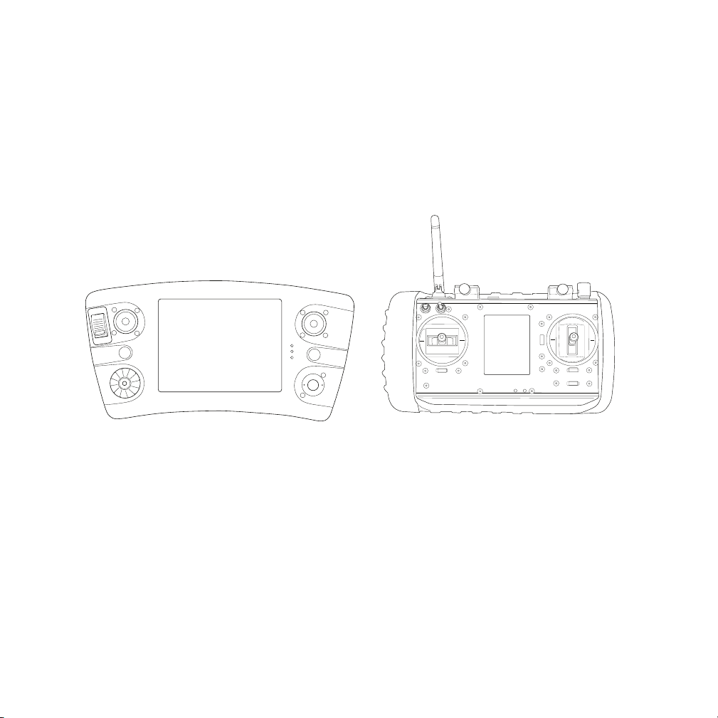
Meet your Draganflyer HHC
This is the original Draganfly Handheld Controller with special attention paid to the
ergonomic layout of switches, controls, the feel, and overall balance of the controller.
The rubber grip and feel reinforces control of the aircraft while the direct sunlight
viewable OLED display, provides easy to read, real-time, aircraft telemetry.
Below you see/learn more about the HHC layout and controls.
Motor engage and
disengage switch
Throttle/Yaw
Yaw trim
Flight mode
control
SD flight log
memory
Camera shutter
Camera tilt
Pitch/Roll
Pitch/Roll trim
Camera zoom
Power on/off
Page 5
Page 7

Along the backside of the controller within easy reach is the spring loaded trainer switch
and the battery charger connections. As the name implies the trainer switch is used in
conjunction with another handheld controller connected using a wireless link between
instructor and student. When the instructor depresses the switch, it instantly passes the
instructor designated controls over to the student. Letting go of the switch immediately
resumes instructor control.
The HHC battery is a 3 cell LiPo that is easily charged using the balance port and main
power charge plugs. Later in this manual charging is discussed in more detail.
Below you see the backside components and connectors.
Datalink
antenna
Spring loaded
trainer switch
LiPo balance
connector
Main LiPo battery
charge plug
Page 6
Page 8
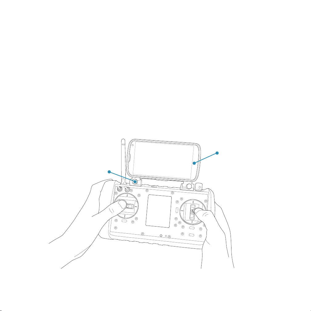
The HHC can be used as a standalone controller or it can be fitted with a Nexus digital
display. The display can be used as a handheld device by your observer, client, or if you
prefer having the display attached it quickly locks into the HHC using two 1/4 turn spring
loaded pins.
The Nexus display is used in conjunction with Draganfly digital video downlink payloads,
digital base station, and comes pre-configured with the DraganView Lite APP.
The APP and network are set-up and configured at the factory so all you need to
remember is that when you’re out flying, you always turn-on the base station first to
establish a network, then power-on the helicopter, controller and Nexus. For more
detailed set-up instructions for the digital video downlink network, refer to the “Digital
Video Downlink” manual.
Nexus digital
Display is attached using 1/4 turn
spring loaded plungers or it can be
used as a handheld display by
your observer or client.
video display
Page 7
Page 9

Contents
Chapter 1: Understanding the HHC
This is one of the more interesting and important chapters
because we’ll go over each and every screen that makes up
the handheld controller. It’s technical, in-depth, and we’ll do
our best to make it fun too.
Chapter 2: Battery Safety and Charging
The HHC is powered by a Lithium Polymer battery so please
take time to read this chapter. Lithium Polymer (LiPo) battery
technology has improved greatly over the years; but if not
cared for properly, the batteries can be very dangerous.
Chapter 3: Ready for flight
At this point you know where all the switches are, what they
do, and you’re more than ready to get out flying so wait no
more; in this chapter we’ll run through preparation for your
first flight and a typical mission scenario.
Chapter 4: HHC technical data
Here you’ll find the specifications and technical data
required to answer many of the questions asked by your
agency responsible for the National Air Space (NAS) or
neighbor down the street.
Page 8
Page 10

Chapter 1
Page 9
Page 11

Understanding the HHC
Acquire New
Config
SN 0x7ACFG436790B1C
TX
Battery
Looking for
Draganflyer
The standard handheld controller (HHC) might not look as fancy or as sophisticated as
the Draganfly GCS, but there is no question that over the years, it has proven to be an
excellent, simple, and reliable flight controller.
The sunlight viewable OLED screen is easy to read, features touch screen navigation
and provides real-time, easy to read, aircraft and system telemetry data. The user
interface is simple and the controller provides fine, precise control over the aircraft and
payload system.
And although the HHC looks different
than the GCS, the HHC is capable of
flying all the Draganfly series aircraft
and wirelessly pairing to work in
conjunction with the GCS. The HHC is
often paired with the GCS or another
HHC for flight training or combined
mission work when an observer or
dedicated camera operator is required.
Keep in mind the HHC operates on a
three cell LiPo battery so make sure to
set your charger correctly. Also keep in
mind that when powering off the
system, you need to hold the HHC
power button for “four” seconds to
power off the controller.
To get started, please power-up the
HHC by pressing the red “power”
button.
When the HHC boots-up
youʼll here it beep and youʼll
be presented with either the
Start Screen as seen here or
the HHC “Home Screen”.
To power on, momentarily
press power switch until
you hear the HHC beep
and let go.
Page 10
Page 12

Screen navigation and hierarchy:
Acquire New
Config
SN 0x7ACFG436790B1C
TX
Battery
Looking for
Draganflyer
To get things started we’ll take you through the screens and functionality of the standard
handheld controller (HHC). As we step through the screens we request that you remove
all the props from your helicopter and power-on the aircraft.
Special notice:
For safety reasons, please remove all props from the aircraft now.
On power-up the aircraft is looking to make a connection with the last controller it was
connected to. So for example, if your GCS or another HHC had been connected earlier
to the aircraft, the aircraft is busy looking for the same GCS or HHC. To get connected
you’ll have to force the aircraft to “acquire a new” controller.
In this example when the new HHC is powered on, it won’t automatically connect to the
aircraft because another controller had been flying the
helicopter. When you tap the screen with your finger to
select “Acquire New”, a screen will pop-up to
acknowledge the new connection and you’ll be taken
to the controller config screen. From there tap “Views”
to be presented with the HHC home screen.
And let’s say that for the next week you’ll be flying the
helicopter with the same HHC. When the system is
powered on, you’ll briefly see this screen for about 10
seconds and then be automatically connected with the
aircraft.
The only time you’ll really have to use this screen when
the aircraft is powered off or has been flown using
another controller.
Page 11
Page 13

Home Screen
00.0
TX
Battery
Basic Inertia GPS
Heli
Battery
Data
Link
GPS
SVs
GPS
PDOP
Altitude m Climb Rate m/s Speed m/s
0.0 0.0
+000 +000
NN
12.2
V
0
V N/A 0 99.9
Time: 00:00
Flight: 00:00
Heading Bearing
Views
Config
The vast majority of your time flying the aircraft will be using the primary HHC home
screen.
This screen provides essential real-time graphical aircraft and system status. And
although the HHC will provide audio alerts to status changes and critical warnings, it’s
always a good idea to develop the habit of visually scanning the screen on a regular
basis during flight.
Always takes you
back to the HHC
“Home Screen”
This section of the screen
contains real-time aircraft
performance information
Aircraft heading
and bearing
symbol
Detailed aircraft
flight data
Detailed aircraft
sensor information
Navigate to the
HHC configuration
screen
Aircraft telemetry and
HHC information
Detailed aircraft
GPS data
Page 12
Page 14

Let’s take a few minutes to describe screen navigation, the information being displayed
and how it’s used.
Starting at the top of the screen we have two navigation buttons that when touched, will
take you to the Configuration set-up and control screens or return you to the main
“View” or more commonly called the HHC Home Screen.
On the home screen we see:
Time: GMT received by the helicopter. To have the time reflect the proper time in your
area, under the Configuration section you need to enter the proper GMT offset in hours
difference.
Flight: What you see displayed is the actual flight time of the aircraft. The flight timer
starts when the aircraft executes an automated takeoff and stops when the aircraft lands
and the motors are disengaged. The time value is actually stored on the aircraft so what
this means, is the time value will not be reset to zero until the helicopter is powered off.
And this is a good thing because for example, you pop-up for a quick flight and let’s say
you log 4 minutes flight time taking still photos. You come back into land, disengage
motors and quickly switch the camera to shoot video. To takeoff again you engage
motors and execute an automated takeoff, starting the flight timer again. The time on the
timer indicates time the aircraft is in the air.
Heading and Bearing: This is a multi-function display that can be very useful with digital
readouts on either side. A helicopter has the ability to be pointed one direction, but fly a
completely different direction. For example, the aircraft can be pointed north, but fly
sideways in an easterly direction. Unlike an airplane, the heading and bearing can be
wildly different.
The center aircraft canopy symbol indicates the heading of the aircraft in relationship to
true North. A directional arrow will become visible when the aircraft is moving to indicate
the bearing, or direction the aircraft is actually moving. Using the same example from
above, if the aircraft is pointed north and flying sideways east, a small arrow will be
visible pointing east on the dial.
Page 13
Page 15

Altitude, Climb rate and Speed: The readouts are real-time and are a good size so they
00.0
TX
Battery
Basic Inertia GPS
Heli
Battery
Data
Link
GPS
SVs
GPS
PDOP
Altitude m Climb Rate m/s Speed m/s
0.0 0.0
+000 +000
NN
12.2V0
V N/A 0 99.9
Time: 00:00
Flight: 00:00
Heading Bearing
Views
Config
0.0
Heli 0.0V TX 12.2V Link N/A
Basic Inertia GPS
Attitude
Time: 00:00
Flight: 00:00
Views
Config
0.0
0.0
0.0
0.0 0.0
Magnetometer Velocity m/s
0
0
00
0
Temperature Throttle
Roll Right North
Pitch Forward East
Yaw Down Down
Time: 00:00
Flight: 00:00
Views
Config
0.0
Lattitude GPS Altitude
0.0
GPS Accuracy Position Errors
Vertical:
---
Heli 0.0V TX 12.2V Link N/A
Basic Inertia GPS
Longitude Barometric Altitude
Horizontal:
North:
East:
Down:
GPS Quality
Satellites:
PDOP:
0.0 0.0
---
---
---
---
---
---
are easy to read. More times than not you’ll develop a trained eye to quickly scan and
check the aircraft altitude and because you’re operating a direct line-of-sight aircraft,
most often you’ll have a good sense of climb rate and speed by just watching the
aircraft.
Live telemetry data: We found that is was very easy and effective to simply view a color
bargraph and get a good idea of aircraft performance. The colors range from Green
(good) to Red (bad) complimented by a digital readout value of the item being measured.
Develop good habits from the start and regularly “scan” this screen to check the health
of the aircraft during a flight and unless you have a very good reason, please don’t
“push” the boundaries. For example, some people will drive around in their car even
when the fuel tank indicates empty. In a car running out of fuel simply means the car will
stop driving but in an aircraft, it means the aircraft is coming down.
Please always scan your telemetry console, watch your controller battery, helicopter
battery, datalink and when it’s time to change a battery, or stop to charge your controller
please take the time to do it.
Different views: Almost 100% of the time you’ll be watching the Basic Home Screen but
if you need to see real-time aircraft sensor, or GPS information, this is where you find it.
Below you see the three “views”.
Page 14
Page 16

Configuration Screen
Views Config
Basic
Config
Flight
Timer
Find New
Helicopter
Helicopter
Calibration
Trainer
Setup
Video
Setup
Time: 00:00
Flight: 00:00
Transmitter Firmware Version 0.9.8e
The configuration screen provides access to a series of six other screens used to set-up
the system.
Please note that helicopter calibration functions have since been automated to set
aircraft magnetometer declination and inclination. As a result, the adjustment and
customer calibration is no longer required.
Most of the screens are very intuitive and will be described in more detail on the
following pages.
Another layer of six setup
screens to adjust LED
brightness, time zone, camera
tilt, display units, transmitter
setup and altitude limit. More
detail is provided in the
following pages.
Basic flight timer to sound
an alarm at the preset
time.
Always takes you
back to the HHC
“Home Screen”
Used to connect
the HHC with a
new helicopter
No longer required
for use in the field
Navigate to the
HHC configuration
screen
If the HHC is configured with a
video receiver, this screen sets
the “receive” channel. To receive
analog video, make sure both
the video Tx and receiver Rx are
set to the same channel
Defines the HHC trainer
mode similar to the GCS
setting up the primary or
secondary controller
Page 15
Page 17

Views Config
Heli LED
Brightness
Time Zone
Setup
Camera Tilt
Setup
Altitude
Limit
Transmitter
Setup
Display
Units
Time: 00:00
Flight: 00:00
Basic Configuration
You’ll find that there are settings
Set Done
Acquire New
Searching for Draganflyer
Draganflyer
Vehicle
Make sure your vehicle is
turned on.
Set
Done
Flight Timer
20.00
The transmitter will issue
a warning after this many
minutes of flight.
you change once and leave them
alone, and there are others that
you change on a regular basis.
For example, unless you’re doing
a lot of traveling, Time Zone is
typically set once while depending
on the project, you might change
the Helicopter LED Brightness,
Camera Tilt and Altitude Limit
much more often.
During daylight hours we
recommend that you have
navigation LED brightness set at
100%. If you’re flying near sunset
or later in the evening they might
be too bright. For late night flying
try a 10% or 20% setting.
Sets a flight timer alarm value. The
timer starts when the aircraft takes
off and sounds an alarm when
time expires.
Some people will use this timer to
alert them when a predetermined
time has passed. For example,
alert me when 10 minutes has
expired or in the case illustrated
above 20 minutes.
There are two different ways to get
connected with a helicopter. Most
often you’re making a connection
at initial system power-up and you
will be prompted at that time to
establish a connection as
described earlier on page 10.
If for some reason you skipped
over the initial start-up screen and
still need to get connected with
the helicopter, you can either
navigate to this screen to make
the connection or power off the
HHC and start over.
Page 16
Page 18

Auto
Done
Always On Always Off
Video Mode Setup
Receiver Channel
1 234567
Audio Settings
Power Settings
If your HHC is equipped with a
Done
Off Master Slave
Trainer Mode Setup
OK
Cancel
You must read and understand the
calibration section of the manual
before proceeding. Incorrect
calibration may adversely affect
flight performance.
WARNING
dual diversity analog video receiver
this screen is used to set the video
receive channel, video audio, and
Rx power management.
And it’s kind’a tricky because on
the Tx we start from “0” so on the
Tx CH 0-6 corresponds to Rx CH
1-7.
The video transmitter and receiver
must be set to the same channel
number to receive a signal and the
audio setting is either on or off.
The default power setting is “Auto”
unless you have a specific reason
to change it, we recommend that
you keep it at this setting.
In the auto setting, the receiver is
only powered-on when a video
output device is connected to the
controller such as video glasses,
video recorder or external display.
A more detailed explanation of the
trainer mode setup is provided
later in the manual but it’s this
screen that is used to setup the
relationship between the
controllers.
Over the years terminology has
changed where in the newer GCS
the terms Primary and Secondary
controller are used because they
more appropriately describe the
relationship.
The dual controllers can be used
for flight training and they are very
commonly used to enable a
separate camera operator. By
splitting the functionality the pilot
can focus on flying the aircraft
while the camera operator focuses
their attention to getting the
photos or video required.
Any screen that starts out with a
warning will always get your
attention. And as it turns out over
the years the team at Draganfly
have eliminated these tricky
adjustments, and that’s a good
thing.
You can disregard the need to try
and make these adjustments
because based on the current
GPS position of the aircraft, the
autopilot is automatically
calibrating the helicopter,
magnetometer declination and
inclination for you.
If you really want to see what’s
behind this screen contact
Draganfly for more information to
gain access.
Page 17
Page 19
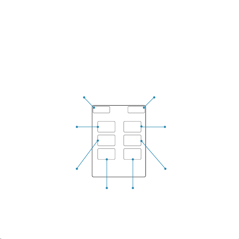
Basic Configuration Screen
Views Config
Heli LED
Brightness
Time Zone
Setup
Camera Tilt
Setup
Altitude
Limit
Transmitter
Setup
Display
Units
Time: 00:00
Flight: 00:00
Basic Configuration
The basic configuration screen provides access to a series of six other screens used to
set-up the system.
Please note that with camera tilt, if you are using a payload gimbal with gyro stabilization
the lower and upper tilt range values must be set at 511 with rate control disabled for
the payload to function properly.
Most of the screens are very intuitive and will be described in more detail on the
following pages.
Used to adjust navigation
LED brightness from 0 to
100% illumination
Always takes you
back to the HHC
“Home Screen”
From this screen you
enter your GMT offset
time value
Sets camera tilt
limits and rate of
speed
Sets a hard
ceiling for the
aircraft
Navigate to the
HHC configuration
screen
Sets your preference for
either Metric or Imperial
measurements used for all
readouts.
Learn the different
sounds and tones
used by the controller
Page 18
Page 20
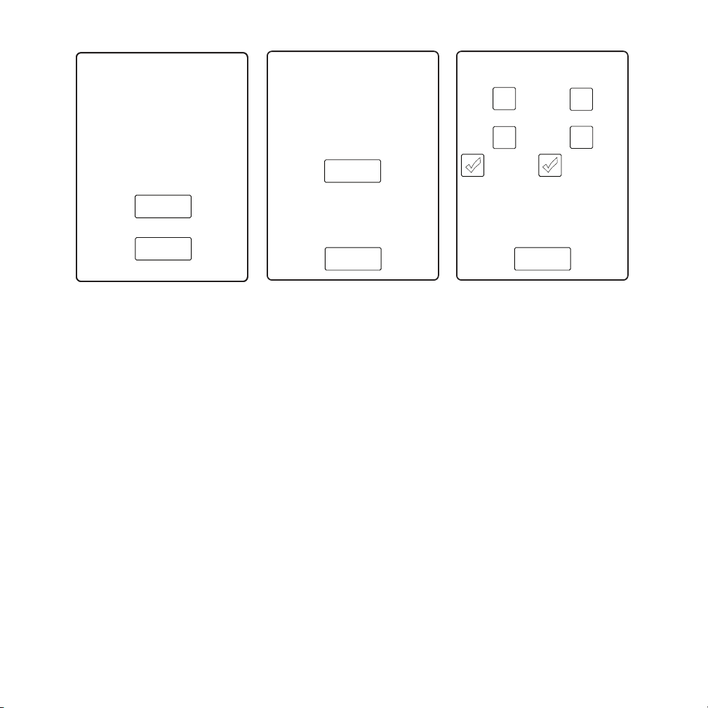
Set
Done
Helicopter LED
Brightness
85%
The screen itself and others are
Set
Done
Time Zone
-6.0
This is the GMT offset of
your local time zone
Done
Tilt Setup
-511
Lower Limit
Upper Limit
356
Reverse
Disable Rate
Control
-
-
+
+
very simple and intuitive. It’s
always a good idea to make setting
changes while the helicopter is on
the ground because when the
helicopter is in the air, your
attention should be focused on
flying.
Experiment with different settings
because everyone has a different
preference. Typically in daylight
hours 100% is the standard setting
but flying indoors or later in the
evening or night, the LEDs may be
distracting, blinding and lower
brightness settings might be more
appropriate.
The system gets it’s time from the
GPS onboard the helicopter as
Greenwich Mean Time (GMT).
For example, during daylight
savings time the offset for
California, in the United States is a
value of -7. A standard time offset
for this same area is a value of -8.
If your area doesn’t observe
daylights saving time, you set this
value once otherwise if you want
the time to be correct you will need
to change this value during
standard and daylight time zone
changes.
If you are flying a gyro stabilized
payload both the upper and lower
limits must be set at 511 for the
payload to work properly with rate
control disabled.
If you are flying a standard payload
you can control the end point limits
of travel and by enabling rate
control, set the speed the camera
tilts between the two end points.
For example, you’re shooting video
and you want the camera to rotate
slowly from looking down to up 30
degrees. You can set the speed
and limits before the flight and
then while flying through the
scene, simply “spin” the camera
tilt knob from one extreme to
another and let the camera slowly
pan up as you focus on flying.
Page 19
Page 21
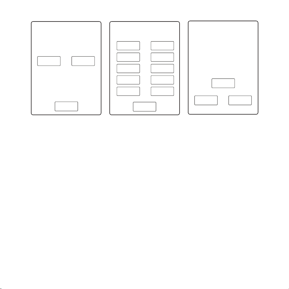
Done
Metric
Imperial
Units
This is typically a screen you use
Done
Use these buttons to learn the
sounds made by the transmitter
Transmitter Sounds
Trim
Adjust
Vehical
Acquired
Vehical
Armed
Low
Battery
GPS
Okay
Trim
Centered
Vehicle
Found
Low TX
Signal
Alarm /
Warning
GPS
Loss
A warning will be issued if the
vehicle reaches this altitude (AGL).
Set this to your provided altitude
limit or 0 to disable.
Altitude Limit
Set
OK
Cancel
70
once after receiving your
equipment to setup your preferred
units of measure.
Setting the system to either Metric
or Imperial will affect every unit of
measure used throughout the
system.
From this screen you can sample
the different warning sounds the
controller will make when it
encounters a status change or
serious warning.
Keep in mind that most warnings
are accompanied by a warning
screen. The warning screens
essentially “take-over” the screen
and must be dismissed by
touching the screen.
The warning screen will only
appear once, but the warning
sound will be repeated until the
situation is resolved.
For example, a low battery will
sound an alarm and bring up a
warning screen. You dismiss the
warning screen, but the alarm will
continue to sound at a regular
interval until you land.
The altitude limit sets an altitude
ceiling limit above ground.
This feature can come in handy
when flying indoors to help
prevent flying too close to the
ceiling in the room or when out
flying a project under a structure
such as a bridge or overhang.
Page 20
Page 22

Primary and Secondary controller setup
Off Master
Trainer Mode Setup
Slave
CH 1-4 CH 5-8 Done
Throttle
Roll
Pitch
Yaw
Off Master
Trainer Mode Setup
Slave
CH 1-4 CH 5-8 Done
Shutter
Ascent
Zoom
Tilt
Hold
The Draganfly system architecture operates over a well defined network and as a result,
we can “invite” other devices to “join” into the network. In this example we powered on
the helicopter and the primary controller. The two have connected and we’ll allow
another controller into the network. Even better, we can define what controls will be
active on the master controller, and when the training switch is depressed, what controls
will be passed over to the secondary controller.
This is an ideal setup for flight
training because as you see
in this example to the right,
we are “passing over” control
of the roll, pitch, yaw and
position hold flight controls
along with camera controls
for shutter, zoom, and tilt.
The controls are “passed
over” when the “training
switch” located on the top left
of the HHC is depressed.
Once the master or primary
controller has been setup,
please turn on the other controller. We want to get the secondary controller connected to
the primary controller so select the “config” button and then select “trainer setup”.
When the Trainer Mode Setup screen is displayed select, “Slave” and then select
“Acquire” connecting the secondary controller to the master controller.
At this point three devices have been connected. The helicopter to the master controller,
and the secondary controller is connected through the network to the master controller.
Page 21
Page 23

With everything connected it’s all very easy to use. Unless the trainer switch is
depressed the primary (master) controller has full control of the aircraft. It’s only when
the trainer button is depressed, that selected controls will be passed over to the
secondary controller.
During flight training the instructor can pass one control over at-a-time until eventually
the student has pitch, roll, yaw and throttle in their control. If at anytime the instructor
needs to resume control, the instructor simply “lets go” of the trainer switch and full
control is instantly restored to the primary controller.
Please note: If for some reason the secondary controller is powered off or gets
disconnected for some reason from the network, the master controller will sound an
alarm tone and all control will be restored to the master controller.
Page 22
Page 24
Chapter 2
SEL
SEL
MODE
MODE
ENT/
ENT/
STOP
STOP
+
-
INC
INC
DEC
DEC
LiPo Charge[sel]
LiPo Charge[sel]
4sPACK C=3.00A
4sPACK C=3.00A
Page 23
Page 25

Battery Charging System
SEL
MODE
ENT/
STOP
+
-
INC
DEC
LiPo Charge[sel]
4sPACK C=3.00A
Please fully read and understand the Lithium battery safety instructions and
warnings section at the end of this chapter before using or charging your batteries.
The operator assumes full responsibility for all risks associated with the use of this
product.
AC power
cord
DC power
cord
Balance plug
Main battery charge plug
Page 24
Page 26

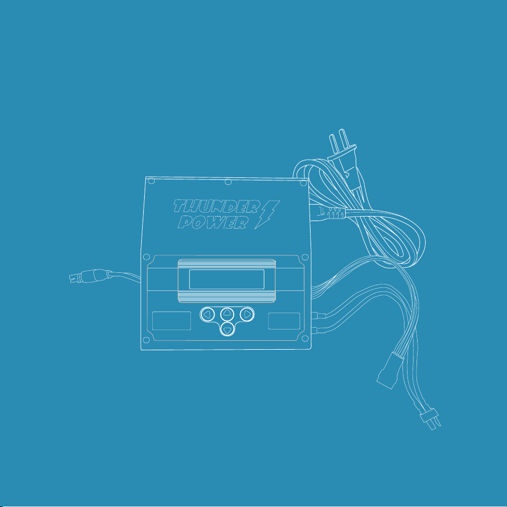
Your Draganflyer system comes equipped with a complete charging kit for the helicopter
and controller batteries used with the aircraft system. The charging system has been
designed for ease of use, portability, safety, and convenience, to keep your systems
charged and flying.
Included with the Draganflyer aircraft charging system is:
! 1 – TP610ACDC single port battery charger (users manual included)
! 1 – 6 wire balancer cable
! 1 – 2 wire charging cable
! 1 – Fire retardant battery charging pouch
"
Setup and Operation
Your charger can be powered from a 110-240 volt AC wall outlet or an 11-18 volt DC
power source such as a car battery. If using an AC wall outlet, remove the cable from the
case, connect it to the power input of the charger, and plug the cable into an AC outlet.
If you are using a 12V battery (car battery), connect the DC cable provided to the
charger. After connecting the cable to the charger first, then connect the alligator clips to
the terminals of your 12V battery (red clip to positive, black clip to negative). When
power is applied, the charger will automatically turn on.
When the charger is powered on, the + and – buttons allow you to scroll up/down
through menus before and during battery charging/discharging. These buttons also
allow you to change values/settings for options after they have been selected (typically
when flashing after pressing the ENTER button).
The SEL/MODE button functions only when you’re not charging or discharging a
battery. Pressing the MODE button will allow you to scroll between the three available
modes:
Page 25
Page 27

• Charge/Discharge/Cycle/Storage Modes
SEL
MODE
ENT/
STOP
+
-
INC
DEC
LiPo Charge[sel]
4sPACK C=3.00A
• Setting Data Mode
• Data View Mode
The ENT/STOP button allows you to select and validate values/settings for options that
can be changed (using the +/– buttons to change) before and during charging/
discharging. Pressing and holding the ENTER button also allows you to start and stop
charging/discharging.
After powering on the charger by default it’s set to ‘Charge Mode’ as illustrated above.
Before shipping your system, your charger was preset by our team for charging the
helicopter flight battery pack, with a setting of 4 cell charging at 3 amps.
Charging the Handheld Controller batteries
Included with your system is the handheld Ground Control System (GCS) and a standard
handheld controller. The GCS is powered by a smaller capacity 4 Cell LiPo battery and
the standard handheld controller (HHC) is powered by a 3 Cell LiPo battery.
Page 26
Page 28

Charging these batteries is just as simple as charging your helicopter battery. The
SEL
MODE
ENT/
STOP
+
-
INC
DEC
LiPo Charge[sel]
4sPACK C=1.70A
connections are the same using the balancer cable and main power charge plug but you
always need to remember that when charging the standard controller, you need to
change the charger cell count from 4 to 3, and reduce your charge current.
Charging the GCS
The GCS is a 4 cell battery and compared to a
helicopter flight pack, charges at a lower current
setting of 1.70Amps.
Connect the balance port connector and the
main battery charge cable to the GCS. The
charge connectors are located and clearly
labeled on the bottom of the GCS.
With the cables connected and the charger powered on, briefly press the ENT button to
step through the display until you select the current setting. When you stop there, the
current setting will be flashing, meaning the charger, charge current value is ready to be
changed.
Press the “-” or (dec) button repeatedly until you step (each time button is pressed the
value will change) the current setting down to 1.70Amps. When you see 1.70 Amps
press the ENT button and the 1.70A value will stop blinking.
The charger should now read 4sPack C=1.70A. If this is correct, “press and hold” the
ENT button and once charging begins let go. The battery is now charging and you will
be notified when charging is complete.
Page 27
Page 29

Charging the HHC
SEL
MODE
ENT/
STOP
+
-
INC
DEC
LiPo Charge[sel]
3sPACK C=1.70A
The standard handheld controller uses a smaller
battery pack with a lower cell count so to charge
this controller you will need to change both the
cell count values as well as the charge current
values.
Connect the balance port connector and the
main battery charge cable to the GCS. The
charge connectors are located on the backside of the HHC.
With the cables connected and the charger powered on, briefly press the ENT button to
step through the display until you select the cell PACK setting. When you stop there, the
cell PACK setting will be flashing, meaning the charger, cell count value is ready to be
changed.
Press the “-” or (dec) button once and the reading will change from 4sPack to 3sPACK.
When you see 3sPACK press the ENT button until you step over to the current setting to
confirm the value is 1.70A. If not, when the value is flashing adjust either the “+” INC or
“-” DEC buttons to create the 1.70A setting.
The charger should now read 3sPack C=1.70A. If this is correct, “press and hold” the
ENT button and once charging begins let go. The battery is now charging and you will
be notified when charging is complete.
Page 28
Page 30
Summary:
The battery charger provided has been preset at the factory to charge the helicopter
LiPo battery pack. The charger connects to the batteries or controllers using two cables.
One cable is a cell balancer cable, and the other is the main charge cable.
When charging the GCS you need a lower charge current setting and with the standard
HHC, both the cell count and the charge current must be adjusted.
Handheld Ground Control System (GCS)
Charger setting = 4sPACK @1.7 Amps
Standard Handheld Controller (HHC)
Charger setting = 3sPACK @1.7 Amps
Standard and maximum charger settings:
• Helicopter battery pack = 4sPACK C=3.00A - maximum current C=5.45A
• Handheld GCS = 4sPACK C=1.70A - maximum current C=2.70A
• Handheld HHC - 3sPACK C=1.70A - maximum current C=2.10A
For additional instructions on your battery charger please refer to the TP610ACDC
battery charger operator’s manual included in your package
Page 29
Page 31

Things you need to know
Special notice:
You might think that we’re exaggerating the issue but no, LiPo battery safety
is something to be taken seriously. If you want to see examples of what can
go wrong just search YouTube for LiPo fire examples. It’s common to think
“this will never happen to me” but that’s why they call them accidents, so
please take battery safety very seriously and here are some tips to consider:
1. When charging your controllers, they won’t fit in a fire proof LiPo bag so
place them on a fireproof surface and monitor them during charging.
2. After charging is complete, always remove/disconnect both cables from
the controller.
3. Keep your controllers out of direct sunlight or high heat conditions. For
example don’t set them on the dashboard of your car. You want to keep the
controllers protected, cool and safe.
4. Some people think “more is better” but no, not with a LiPo battery.
Please only charge the controllers at the prescribed cell count and current
ratings. Trying to “over fill” a battery will result in damage.
5. If you suspect a battery issue with your controller DO NOT disassemble
the controller. Contact Draganfly to get instructions for further testing,
evaluation and/or return to have the battery replaced at the factory.
Page 30
Page 32

Lithium Battery Safety Instructions and
Warnings
Please read and fully understand all of the instructions and warnings below before using
or charging your lithium polymer batteries. Lithium Polymer (LiPo) batteries are
volatile; improper use or failure to follow these instructions and warnings may
result in fire, personal injury and/or damaged property. Draganfly Innovations and its
affiliates assume no liability for the improper use of this battery, or failure to comply with
these instructions and warnings.
General Guidelines and Warnings
• Your batteries are not fully charged
upon receiving them, the batteries
must be charged before use.
• Never leave charging batteries
unattended. When charging LiPo
batteries you must constantly
monitor the charging process and
be there to react to any undesired
results.
• Before charging, press the battery
test button on your flight battery to
check the status and voltage level.
One or more of the status LED’s
should turn on and remain on while
the button is held. Any other
flashing pattern on the status LED’s
may indicate damage to the
battery; please contact Draganfly
Innovations Technical support.
• When selecting the cell count or
voltage for charging, ensure to
select the cell count and/or voltage
that appears on the controller
battery label. Selecting an incorrect
cell count or voltage may result in a
fire.
• Do not exceed the maximum
charge rate current listed on the
controller battery label.
Page 31
Page 33

• Always connect the balance cable
between the controller and charger
while charging or discharging.
permanent damage and premature
deterioration of the battery internal
to the controller.
• Only use a good quality charger
rated for LiPo batteries, such as
the charger including in your
Draganflyer system. A low quality
charger may damage the controller
battery and result in fire.
Storage & Transport:
• Never ship or transport a damaged
LiPo battery.
• Store controllers at room
temperature between 4.5 degrees
C (40 F) and 21 degrees C (70 F).
• Do not store controllers in a vehicle
even if in a flame retardant
container.
• Do not store or expose controllers
to direct sunlight for extended
periods of time.
• Do not expose controllers to
temperatures in excess of 76
degrees C (170 F). Exposure for
longer than 2 hours may cause fire.
• Before travelling with LiPo powered
devices always check with your
airline for their policies and
regulations regarding
transportation of LiPo batteries.
• If shipping the controllers, always
discuss safe packaging and
shipping procedures with the
courier.
• Do not store controllers near a
source of heat.
• Exposing either the GCS or HHC to
temperatures in excess of 65
degrees C (150 F) may cause
Page 32
Page 34

Disposal:
If you believe there is a problem with the battery in the GCS or HHC controllers contact
Draganfly to get more information. Do not attempt to disassemble the controller to
remove the battery.
Special notice:
Never disassemble the handheld controllers to remove the battery, inspect
battery or dispose of the battery. If you suspect a problem contact Draganfly
Innovations.
Page 33
Page 35

Chapter 3
Page 34
Page 36

Ready for flight
In the helicopter manual we describe flying a photo shoot and focus more on the flying
than the actual mechanics of using the HHC to launch and control the aircraft. In this
manual we will cover HHC specific information to:
Get in the air:
• get connected with the aircraft
• arming motors
• engage motors
• initiate an automatic takeoff
What to do when you’re up there:
• GPS position hold
• shooting photos
Landing and shutdown:
• landing
• disengage motors
• disarm motors
• disconnect from the aircraft
Post flight data:
• archive mission log
• archive photos and video
Page 35
Page 37

Get in the air:
Earlier in this manual we had you remove your props and if for some reason they’re back
on the aircraft, please take a minute to remove them. Whenever you’re trying something
new, doing some experiments, or just want the system powered on to check some
settings, it’s a good idea to remove the props to prevent any possible accidents.
Special notice: Please remove all the props from the aircraft now. Only run
motors for very short periods without props or they will overheat.
With the props removed we’ll quickly run through the connecting, arming and engage
motor sequence. The idea is to get you comfortable with the routine and most
importantly comfortable with turning the motors off once you’re on the ground. There is
nothing worse than making a perfect landing only to make a mistake later and flip it over
or do some damage.
Throttle:
Before we actually start the motors it’s important to understand the throttle has a dual
purpose. As illustrated below when the motors are not powered on, the throttle is used
to arm and disarm the motors. Once the motors are running it takes on a new
Lower-left corner
disarms motors
Motors not running
Lower-right corner
arms motors
Yaw le ft
Execute auto take-off
and increase altitude
Decrease altitude
Motors powered on
Yaw right
Page 36
Page 38
personality used to initiate an automatic takeoff and once the aircraft is up in the air, it
behaves just as you might imagine. So basically the throttle control has three different
personalities:
1. arm and disarm the motors
2. initiate an automatic take off and control altitude and yaw
3. control altitude and yaw only
Get connected:
For this exercise make sure the props have been removed from the helicopter, install a
battery and power-up the aircraft.
Power-up the HHC and after booting, if the HHC had been connected with the the
helicopter it will simply “reconnect”. If not, acquire the helicopter to get connected.
Once connected the HHC will update the on-screen aircraft telemetry data and
we’re ready to arm and engage the motors.
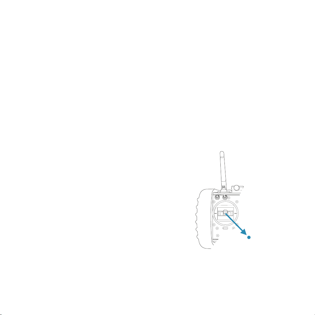
Arming the motors:
With the props removed for this test, move the throttle
down and to the lower right corner of travel. Hold it
there until you hear the HHC series of tones indicating
the motors are armed and also notice, the helicopter
navigation LEDs stopped blinking. When you see
the aircraft with navigation lights on steady it
means - stay away - because the motors are
armed and ready to start spinning at anytime.
With the motors armed make sure to keep your
hands, children and pets away from the motors.
The next step is to engage the motors.
Lower-right corner arms
motors
Page 37
Page 39
Engage the motors:
When you engage the motors it just gets them spinning at a moderate speed. The thrust
is low enough where you don’t have to worry about the aircraft taking off but it’s very
important at this step of the process to make sure that all of the motors are running. As
part of your pre-flight, before initiating an auto-takeoff you must always check to make
sure all aircraft motors are running.
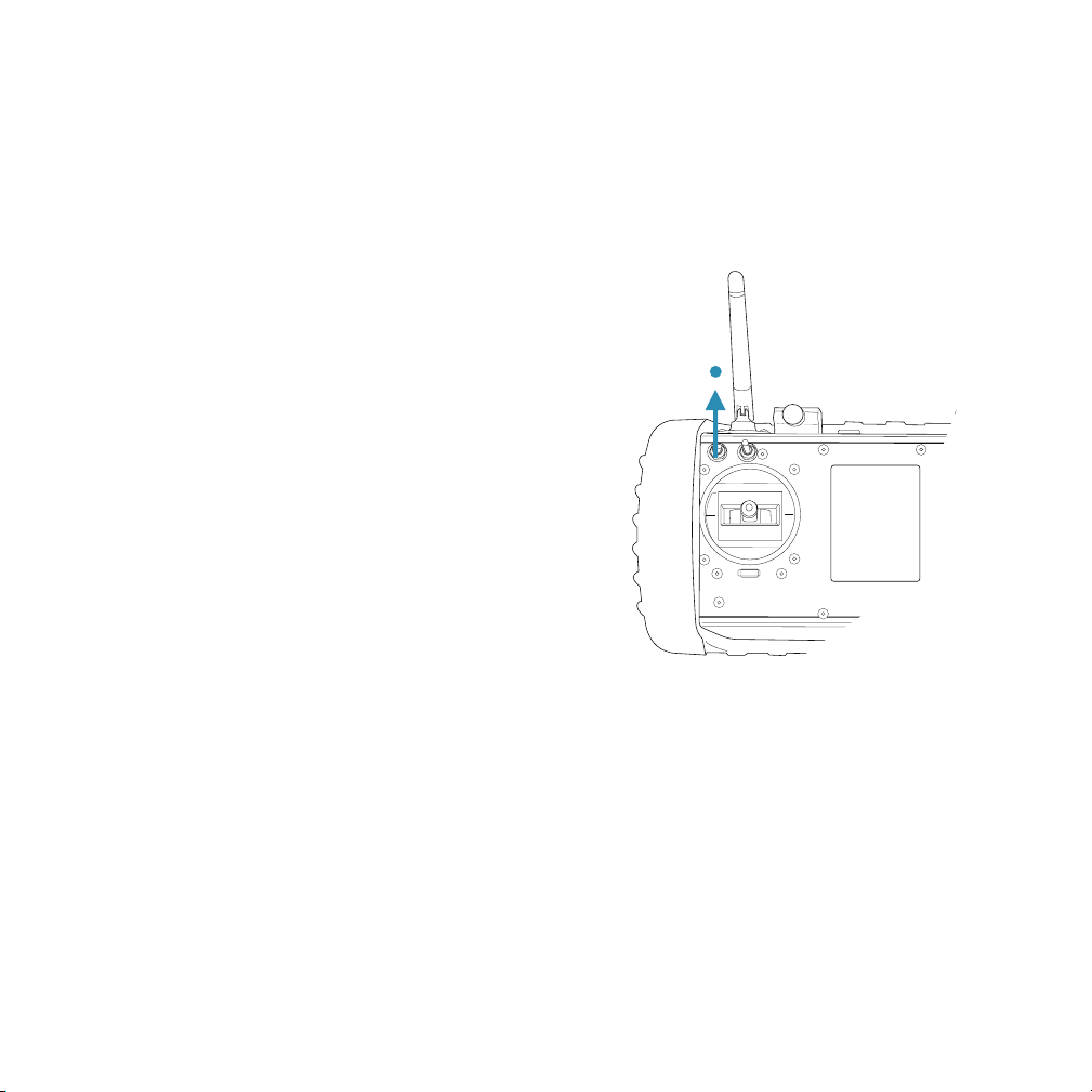
So lets engage motors. Because we have the
props removed when we initiate an auto-takeoff
the helicopter will get frustrated because the
altitude isn’t increasing but not to worry.
The helicopter will try to achieve an
Engage motors
approximate 1 meter (3.2 feet) altitude
but without props you’ll just hear the
motors trying their best to achieve the
desired height.
To engage motors press the front,
upper left, switch “up” and hold for
approximately one second then release.
The motors will start and always, check
to make sure they are all running.
Initiate an auto-takeoff:
To initiate the auto-takeoff you will move the throttle
straight up and hold for approximately one second, then lower the
throttle to the center position. Do not “let go” of the stick as you return it to
center. Please get into the habit of raising the throttle, holding for one second, and
returning it back to the center position in one fluid motion. Once the throttle is back to
center you will hear the motors increase speed as the aircraft attempts to reach the
desired takeoff altitude. Please only let the motors run for a brief period because without
props installed they will overheat.
Page 38
Page 40
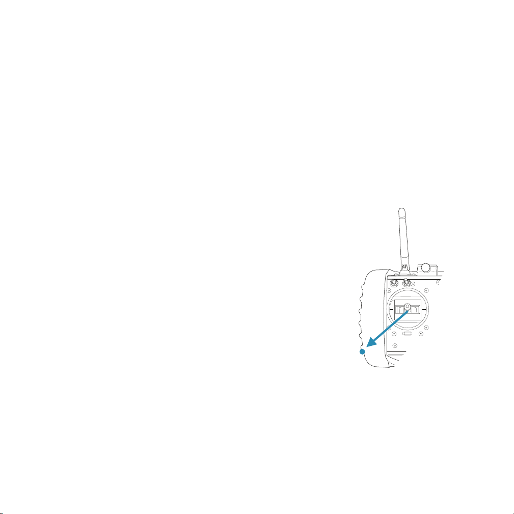
Disengage motors:
In a real flight situation you would be flying the aircraft now and when it was time to land
you would bring the aircraft back, make your descent, and once the aircraft is on the
ground, execute the following procedure.
With the aircraft on the ground you’ll bring the throttle straight back and hold it in this
position for at least one second. After one second keep the throttle in the full back
position, and simultaneously push the motor disengage switch “down”. The motor
disengage switch is located on the front, upper left position.
When depressed the motors will stop.
If you accidentally hit the motor disengage switch too quickly, and the motors don’t
stop, let go of the disengage switch and keep the throttle all the
way back for at least one second before pushing the disengage
switch again. So the trick is to first bring the throttle straight
back, hold for one second, then depress the motor
disengage switch.
Disarm motors:
When the motors have stopped, return the throttle to
the center position. Then move the throttle to the
lower left position and hold it there until the HHC
confirms the motors have been disarmed. When
disarmed the helicopter navigation LEDs will start
blinking and it’s safe to be near the aircraft.
Lower-left corner
disarms motors
Summary:
We had you remove the props for this exercise to
reduce risk and build confidence with the essential
skill of starting and stopping the aircraft motors. Before installing the
props, please take time to practice this routine over and over again to
become very familiar with the process. There is nothing worse than making a great
Page 39
Page 41

landing and then having trouble powering off the motors or even worse damaging the
aircraft. To quickly review the process:
Takeoff:
• arm motors
• engage motors
• check that all aircraft motors are spinning
• initiate an automated takeoff
Landing:
• land the aircraft
• when helicopter is on the ground, disengage motors
• disarm motors
When you are very comfortable with the process, power off the aircraft and install the
props so we can do some real flying.
Get in the air: (we’ll really fly this time)
After running through the previous exercise you’re now experienced at starting and
stopping the motors and familiar with getting the aircraft into the air, so it’s time to get
flying. The information you find here compliments and in some cases is replicated from
the “Helicopter Flight” information you find in the helicopter manual.
The “Get in the air” info provided in this manual is geared more towards the unique
aspects of the HHC and how you get the most out of the system. To get a good
understanding of flying the system we recommend that you read and use both manuals.
Before any flight, you want to preflight the helicopter and the HHC system so as a quick
review, the preflight graphic for the helicopter is provided along with a preflight for the
GCS system.
Page 40
Page 42
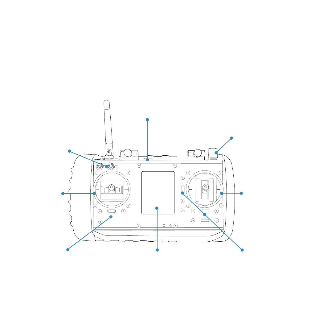
HHC preflight frontside
In addition to conducting a preflight on the aircraft it’s just as important to preflight the
HHC before powering up the system and getting up in the air.
You want to look over the HHC for any physical damage, check the battery voltage,
make sure the joy sticks are operating smoothly, double check all the settings, set the
antennas to the proper position, and make sure switches are in the right place before
lift-off.
Data log SD
memory card
installed
Adjust camera
rotation to the full “up”
Flight mode switch
should be in the
center position
position before takeoff
Check to make sure
the throttle/yaw
gimbal operates
smoothly
Check that Yaw
trim is centered
Clean display if needed and ensure
touch screen is working properly
Check to make sure
the Pitch/Roll gimbal
operates smoothly
Check to make sure both the
Pitch and Roll trims are centered
Page 41
Page 43

Helicopter preflight
Just like a real aircraft it is very important to pre-flight the Draganfly helicopter to make
sure it’s airworthy. We recommend a static on-the-ground pre-flight as illustrated below,
and once you have taken off, we suggest a second flight check in a hover to make sure
the aircraft and system are behaving properly. If you have any doubt, or suspect a
problem, either cancel the mission or abort the flight until the problem is corrected.
Double check to ensure the
Ensure booms are
locked firmly in place
Spin all motors by hand
to make sure they spin
smoothly
canopy is secured tightly
If you are flying with a
payload, make sure
attachment screws are
securely fastened and
camera is properly
secured to the camera
mount
Check you props to make sure
they are locked securely in
place and double check props
for nicks or cracks
Double check and make sure
landing gear is firmly locked in
place
Draganflyer X4-ES System Pre-flight Check
Page 42
Page 44
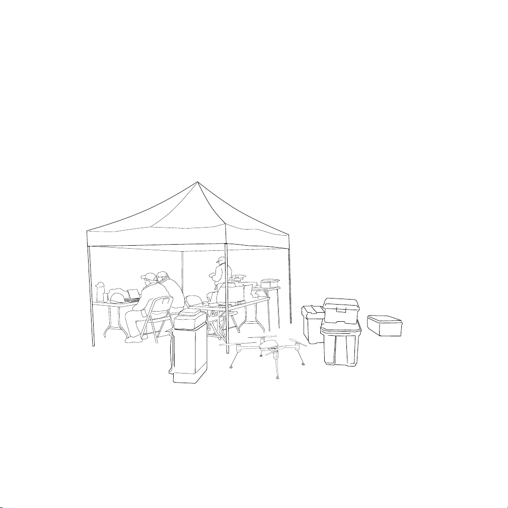
The mission:
In the flight scenario described in the helicopter manual we were focused on explaining
information about the aircraft itself versus the HHC during a typical photo shoot but in
this scenario, we’re more focused on the HHC while flying a mission at a train
derailment. We strongly encourage that you read and understand both scenarios to get
a well rounded understanding of the system.
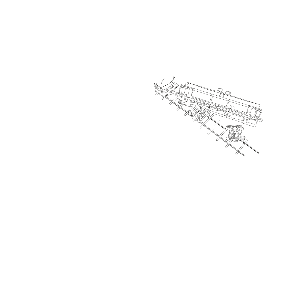
In this scenario the task for our flight team is to provide HAZMAT personnel with critical
tanker car information, understand the extent of damage and shoot aerial images
documenting the crash scene.
Our flight crew consists of three people and the team has staged personnel and their
equipment at a safe distance from the accident. In the crew we have the pilot, camera
operator, and a spotter, to monitor the airspace and general flight area.
Page 43
Page 45

Pre-planning:
H
Safety is always a priority so before flying, the flight team designates a primary takeoff
and landing area along with two safety zones. The safety zones are designated areas to
be kept clear of personnel and equipment in the event the aircraft needs to come down
quickly. Keeping the zones clear protects team personnel and it protects the aircraft
from accidentally hitting something in the event of an emergency landing.
Trees
Train tracks
Safety Area 1
Clear of people
and equipment
Trees
CRASH SITE
STAGING AREA
Dirt Road
Safety Area 2
Clear of people
and equipment
Helicopter takeoff
and landing area
Page 44
Page 46

Get the data:
This first flight is to get up in the air to determine the extent of damage, check for leaking
fluids and read markings on the tanker cars. The second flight will be flown to gather
more data and we estimate a third or fourth flight to document the scene and the work
of response personnel.
With both the GCS preflight and aircraft preflight completed we’re ready to get into the
air. The helicopter system is brought over to the designated takeoff and landing area and
we then:
• power on the helicopter and HHC
• remove lens cap and power on the camera
• connect to the aircraft
• connect to the secondary controller being used by the camera operator
• verbally announce to personnel, the aircraft will be lifting off
• check video down-link
• check video and camera controls
• check the immediate airspace for other aircraft and obstacles
• arm the helicopter
• check helicopter GPS accuracy and ensure you have enough satellites
• verbally announce helicopter is lifting off
• engage motors
• check to make sure all aircraft motors are spinning
• initiate an automatic takeoff
• during the preliminary hover, conduct a second preflight to ensure helicopter and
system are behaving properly
• double check airspace
• ascend and fly forward at a nice climb rate to get above trees enroute to your first
target
As the helicopter climbs out and you fly towards the crash site the camera operator will
provide you with directions and working together, as a team, you will work the crash site
to gather the data and photos needed. During the flight the spotter will monitor the
Page 45
Page 47

airspace, keep the safety zones clear of people, vehicles, and also keep an eye on the
aircraft.
What to do when you’re up there:
As you slowly fly over the crash site the camera operator will suggest the best spot to
“park” the helicopter in a GPS position hold to get the photos needed. When you switch
into GPS position hold using the mode switch on the front of the HHC, it’s always a
good idea to slow the aircraft to a hover, then initiate the GPS position hold.
Relax, keep an eye on the aircraft, the
wind, and work as a team with your
camera operator to get the photos
needed. When you’re in a GPS position
hold often the camera operator will
request that you yaw or rotate the
aircraft. And because the autopilot is
holding a stationary hover, it’s all pretty
easy.
During the flight it’s always a good idea
to visually “scan” your telemetry data to
keep an eye on your altitude, datalink
signal strength, GPS position accuracy,
and battery health. When your aircraft
battery gets down around the 14.4vdc
value you know that within a few minutes
you’ll get your first battery warning and need to start thinking about returning to land.
When you need to move off to a new location it’s always a good idea to bring the aircraft
back into the “safety position” before releasing the GPS position hold. The safety
position is something you learned during flight training and it was discussed in the
helicopter manual. The idea is very simple. Yaw the aircraft into a position where you see
the two white navigation lights. This means the rear of the aircraft is pointed towards
you, bringing you in line with the aircraft, making it easier to fly.
Page 46
Page 48
Release the GPS position hold and fly to the next location to shoot more photos. As you
SUNEX 61985
approach the next GPS position hold spot, slow the aircraft into a steady hover and
engage the GPS position hold.
Always remember that you’re the pilot in command of the
flight. If the winds get too gusty, you see some rain
moving into the area or you’re not comfortable
with the conditions you can either abort the
flight or not even execute the mission. The
safety of the crew and anyone in the area
is your responsibility so take this all very
seriously.
When you receive the first battery
warning it’s always a good idea to start
heading back to the takeoff and landing
area. A battery change is a quick affair so
why take any risks, and unless it’s an
emergency why push the battery to it’s limit.
If you are an experienced pilot and comfortable flying the aircraft in any orientation,
release the GPS position hold and head back. If you’re more comfortable starting out
from the safety position, yaw the helicopter into position before releasing the GPS
position hold.
Landing and shutdown:
As you return to the takeoff and landing area clearly announce to everyone the aircraft
will be landing. As you make your approach do not fly over people and if possible make
as direct an approach as possible.
As you get closer make sure the camera operator rotates the camera “up” as far as
possible to help keep the lens clean during landing. Clearly announce one more time the
aircraft is landing and bring the helicopter in.
Page 47
Page 49

When you get the helicopter on the ground you will:
• aircraft touches down, disengage motors
• disarm motors
• power off the camera
• power off helicopter
• power off the HHC
Post flight data:
After flying the mission it’s a good idea to create a folder on either a laptop out in the
field or when you get back to your office on your desktop system to archive the flight
data and photos.
Create a folder with the case number, project number or name for the project. Remove
the micro SD memory card from the HHC and copy the flight logs into the folder. In the
above scenario we flew four flights, so you’ll need to copy the last four log files from the
HHC.
Also create a folder for the flight photos and video. Remove the memory card from the
camera and copy the mission photos and video into the appropriate folders.
Summary:
In this chapter we covered quite a bit of information ranging from the basics of arming
and engaging the aircraft motors, running though a mission scenario and combined with
flight information in the helicopter manual you should have a good grasp on the basics
of flying and operating the aircraft.
The Draganflyer helicopter system and the handheld controller (HHC) are an effective
combination. We have gone to great lengths to make it “simple” and at the same time,
provide you with some amazing capability.
Enjoy your flying and if you have additional questions or need additional support please
contact us by e-mail or give us a call.
Page 48
Page 50

Chapter 4
Page 49
Page 51

Troubleshooting
Problem: How do I get the best range with the system
Possible cause:
• Antenna orientation
Solution: Please keep in mind this is a “line-of-sight” vehicle and is not intended to be
flown as an FPV aircraft. To get the best rage for data and video, it’s important to know
the “weakest” signal condition is when the tip of the antennas is pointed towards the
aircraft.
The ideal antenna orientation is to have the “long side” of the antenna facing the aircraft
so you will see people accomplish this in different ways. Some people prefer to have the
antennas pointed back towards themselves, while others prefer to have them pointed off
to the sides.
When talking about video range remember that with the analog video downlink system
you have a foldout patch antenna on the backside. In addition to the proper orientation
of the omni antenna on top of the controller, unfold and orient the patch antenna so the
flat side is pointed towards the aircraft.
With the digital video downlink system you must power-on the base station first and
place it in a central area clear of obstacles.
If you continue having problems contact Draganfly for more information.
Problem: There is no live video displayed (analog system)
Possible cause:
• Camera powered off
• Payload is not plugged into helicopter
• Video glasses not powered on
Page 50
Page 52

• Wrong video channel selected
Solution: After checking the simple things first like camera power, lens cap, video
glasses power and making sure the payload is plugged into the aircraft double check the
video transmitter channel number. By default everything is shipped with CH1 as the
default. Double check the video Tx is set to channel number one.
On the HHC power-up the controller and go to Config, Video Setup, and select CH1 as
the receive channel. By default the Power Setting is set “Auto” so double check to make
sure it’s set properly and press “done”.
With everything powered on, check video.
If you continue having problems contact Draganfly for more information.
Problem: There is no live video displayed (digital video system)
Possible cause:
• Base station must be powered on first
• Helicopter must be powered on
• Payload is not plugged into helicopter
• Nexus is the last device to be powered on
• Must launch the DraganView App to display video and select the “play” button
• When first connected, it might take up to 30 seconds to start receiving video
Solution: The digital downlink network system might sound complicated but it’s
actually very simple. The only danger is that possibly people are tempted to make
configuration changes to the Nexus so please resist the urge. However, if you did make
changes and call the support line for assistance - please tell them immediately that you
made changes because it will speed the trouble shooting process.
Keep in mind the base station gets powered-up first to establish a network. When the
helicopter payload is powered-up, it’s looking for this network and will auto-connect.
When the Nexus is powered on, it’s looking for the network and will auto-connect.
Page 51
Page 53

Problem: I power on the HHC but I can never connect to the aircraft or pull up my
basic view screen.
Possible cause:
• The number of log files on the SD memory card exceeds 256
Solution: If this happens out in the field simply power off the HHC and remove the SD
memory card, then power back on and you’ll get connected. When you get back to the
office or to a computer archive the log files and either reformat the SD memory card or
simply delete the log files from the memory card.
Reinstall the memory card and everything should be working fine but if not, contact
Draganfly for more information.
Problem: I’m trying to change the camera tilt but it isn’t working.
Possible cause:
• Payload not plugged in
• Camera tilt knob not turned all the way at takeoff
• Camera tilt limit not set properly
Solution: Before takeoff the camera tilt control needs to be rotated to move the
camera all the way “up”. After liftoff the camera tilt will work properly.
So for example lets say the camera knob was set in the middle of it’s rotational range
and you takeoff. As you’re flying you try to adjust camera tilt but it doesn’t work.
If you rotate the knob all the way in the direction to rotate the camera “up”, then the
camera will tilt will start operating.
If that still doesn’t work, make sure the camera tilt setup indicates a range limit of 511
and -512 with rate control disabled.
Still have a problem - contact the team at Draganfly for further assistance.
Page 52
Page 54

Technical Specifications
! Handheld Controller (HHC):
• Width: 22cm (8.7”)
• Height: 12cm (4.7”)
• Depth: 8cm (3.1”)
• Weight: 895g (1.97 lbs)
! Data Link RF Communications:
• Link Type: 2.4GHz two way
• Helicopter Antenna: Wired Whip Antenna
• Controller Antenna: Omni Directional Whip
• Transmission Power: North America: 50mW (+18dBm) International:
10mW (+10dBM)
• Transmission Technique: DSSS (Direct Sequence Spread Spectrum)
• Frequency Band: 2.400 – 2.4835 GHz
• Certification: CE, FCC, IC, ETSI
• Data Link Channel Selection: Automatic (13 channels)
! Optional analog video Link RF Communications:
• Model: Dragan Eye Pro
• Dual diversity
• Link type: helicopter to ground (one-way)
• Receive antennas: flat patch and omni
• NTSC and PAL compatible
Optional external interfaces:
• Two composite video outputs
Page 53
Page 55

Contact Information
Draganfly Innovations Inc.
Product support:
Phone: 1-800-979-9794
International: 1-306-955-9907
e-mail: support@draganfly.com
Sales information:
Phone: 1-800-979-9794
International: 1-306-955-9907
Online: www.draganfly.com
e-mail: sales@draganfly.com
Mailing address:
https://www.draganfly.com
Draganfly Innovations Inc.
2108 St. George Avenue
Saskatoon, SK S7M0K7
Canada
This product and manual are copyrighted by Draganfly Innovations Inc. with all rights
reserved. No part of this product or start-up guide shall be reproduced in any form
without the prior written consent or authorization of Draganfly Innovations Inc. No patent
liability is assumed with respect to the use of the product or information contained herein.
Document Revision Level: v2.1
Page 54
 Loading...