

Page 1
®
DR
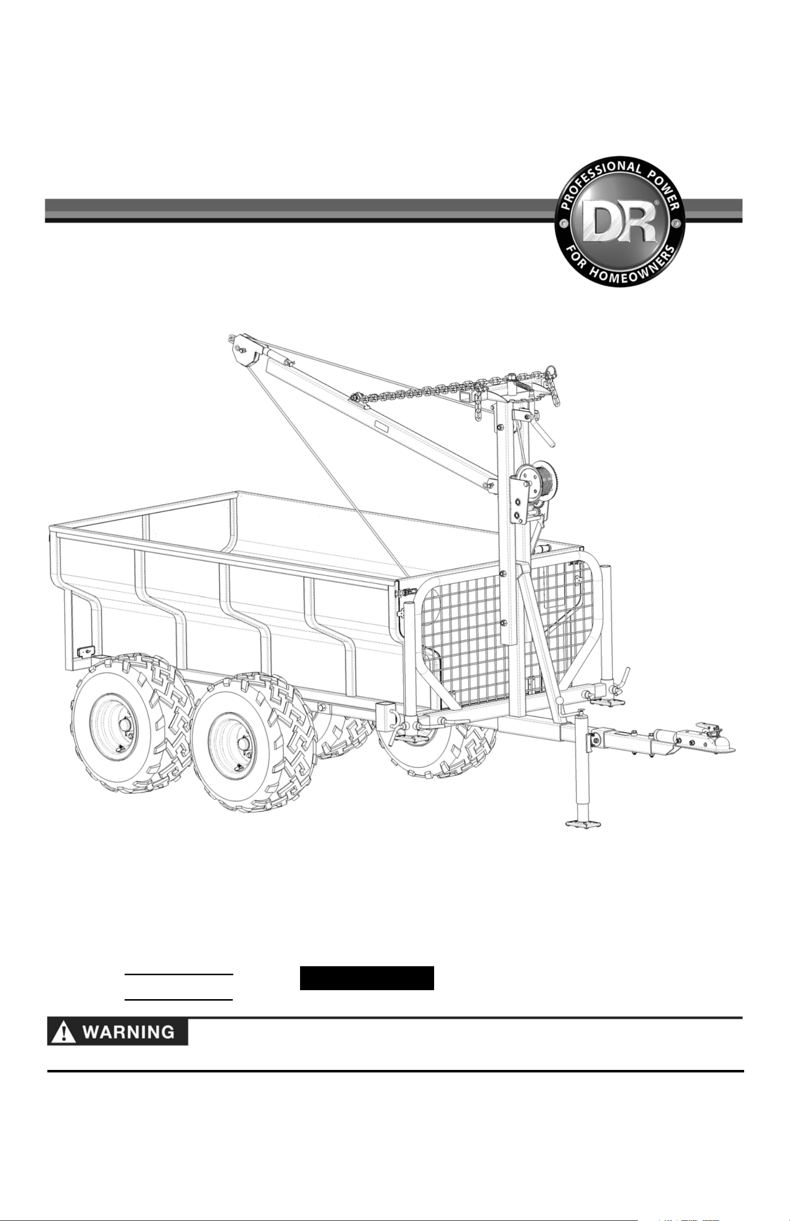
VERSA TRAILER™
SAFETY & OPERATING INSTRUCTIONS
DR Power Equipment
Serial No.
Original Language
Order No.
Read and understand this manual and all instructions before assembling and operating the DR VERSA TRAILER.
Toll-free phone: 1-800-DR-OWNER (376-9637)
Fax: 1-802-877-1213
Website: www.DRpower.com
Page 2

Table of Contents
Chapter 1: General Safety Rules................................................................................................................................................................... 3
Chapter 2: Assembling The DR VERSA TRAILER........................................................................................................................................6
Chapter 3: Operating The DR VERSA TRAILER........................................................................................................................................... 20
Chapter 4: Maintaining The DR VERSA TRAILER .......................................................................................................................................25
Chapter 5: Troubleshooting .........................................................................................................................................................................27
Chapter 6: Parts Lists and Schematic Diagrams......................................................................................................................................... 30
Conventions used in this manual
This indicates a hazardous situation, which, if not avoided, could result in death or serious injury.
This indicates a hazardous situation, which, if not avoided, could result in minor or moderate injury.
This information is important in the proper use of your trailer. Failure to follow this instruction could result in damage to
your Trailer or property.
TIP: This is a helpful hint to guide you in getting the most out of your DR VERSA TRAILER.
NOTE:
This information may be helpful to you in using your DR VERSA TRAILER.
Serial Number and Order Number
A Serial Number is used to identify your Trailer and is located on the Serial Number Label on the Main Frame of your Trailer. An
Order Number is used to check and maintain your order history and is located on the upper left portion of your packing slip. For
your convenience and ready reference, enter the Serial Number and Order Number in the space provided on the front cover of this
manual.
Additional Information and Potential Changes
DR Power Equipment reserves the right to discontinue, change, and improve its products at any time without notice or obligation
to the purchaser. The descriptions and specifications contained in this manual were in effect at printing. Equipment described
within this manual may be optional. Some illustrations may not be applicable to your Trailer.
2 DR®VERSA TRAILER
Page 3
#
Chapter 1: General Safety Rules
Read this Safety & Operating Instructions Manual before you assemble and use the DR VERSA TRAILER. Become familiar with
the operation and service recommendations to ensure the best performance from your Trailer. If you have any questions or need
assistance, please contact us at www.DRpower.com or call Toll-Free 1-800-DR-OWNER (376-9637) and one of our Technical
Support Representatives will be happy to help you.
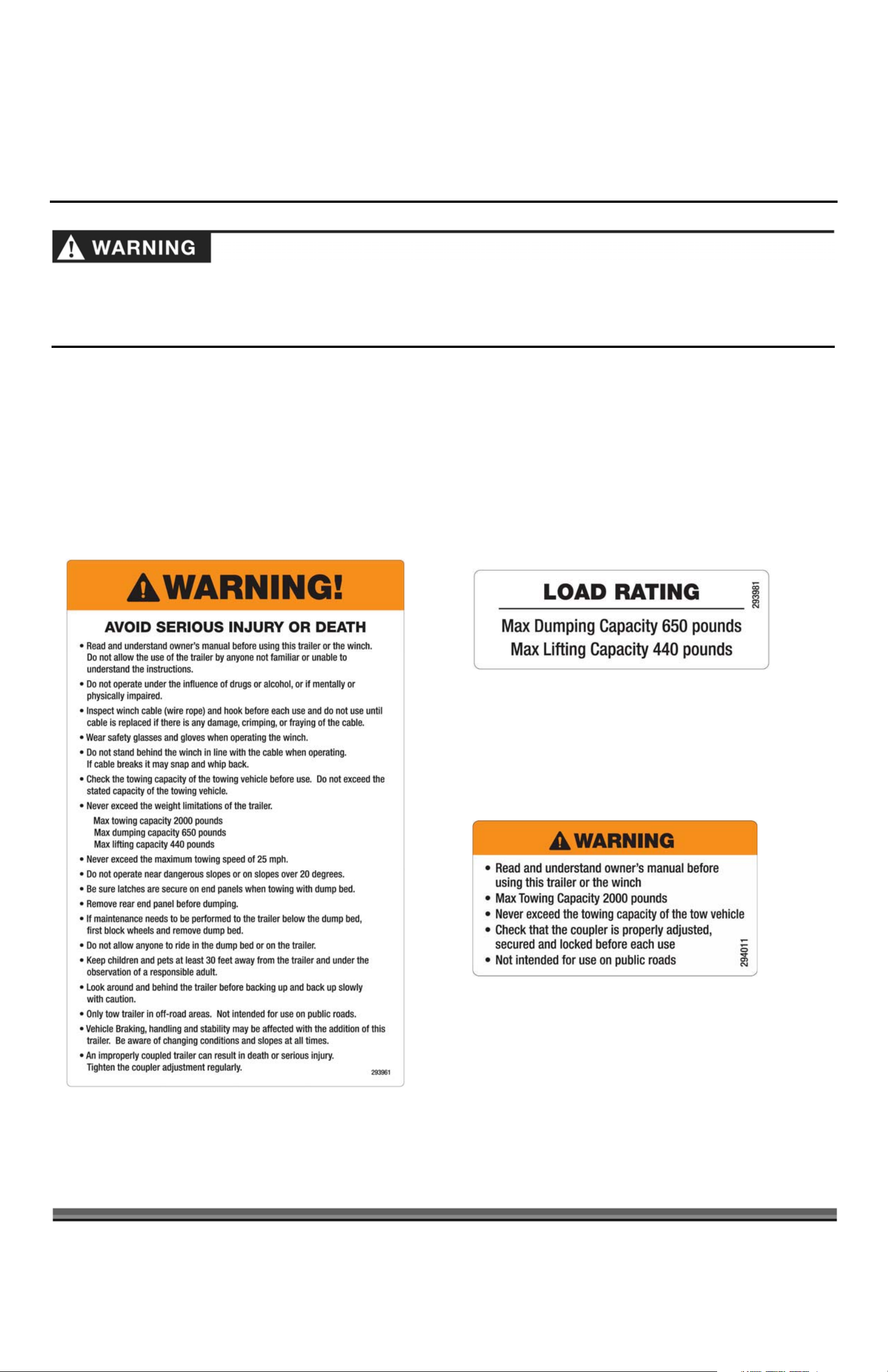
Labels
Your DR VERSA TRAILER carries prominent labels as reminders for its proper and safe use. Shown below are copies of all the
Safety and Information Labels that appear on the unit. Take a moment to study them and make a note of their location on your
DR VERSA TRAILER as you set up and before use of your Trailer. Replace damaged or missing Safety and Information labels
immediately.
293981
#294011
#293961
CONTACT US AT www.DRpower.com 3
Page 4

Protecting Yourself and Those Around You
You must operate the Trailer safely. Unsafe operation can create a number of hazards for you, as well as anyone else in the nearby
area. Always take the following precautions when using this trailer:
x Never exceed the rated towing capacity of the Tow Vehicle. Keep in mind that the operator or user is responsible for accidents
or hazards occurring to other people, their property, and themselves.
x We recommend wearing gloves and protective goggles or safety glasses with side shields while assembling or using the DR
VERSA TRAILER and the supplied Winch.
x Wear shoes with non-slip treads when assembling or operating your Trailer. If you have safety shoes, we recommend wearing
them. Do not assemble or use the Trailer while barefoot or wearing open footwear.
x Wear long pants while assembling or operating the DR VERSA TRAILER and a long sleeved shirt to protect from accidental
scrapes, cuts, or abrasions that may result.
x Do not transport people on or inside the Trailer. The transport of people puts their lives at risk and may be illegal, as the Trailer
has not been designed to carry passengers.
x Do not transport flammable, explosive, poisonous, or other dangerous materials in your Trailer.
Safety for Children and Pets
Tragic accidents can occur if the operator is not alert to the presence of children and pets. Children are often attracted to the
Trailer and the hauling activity. Never
assume that children will remain where you last saw them. Always follow these precautions:
x Keep children and pets at least 30 feet away from the working area and ensure they are under the watchful care of a responsible
adult.
x Be alert and stop what you are doing if children or pets enter the work area.
x Never allow children to operate the tow vehicle or the DR VERSA TRAILER.
x Use care when backing up to make sure the area is clear of children, pets, and other objects that could result in damage or injury.
General Safety
Operating this DR VERSA TRAILER safely is necessary to prevent or minimize the risk of death or serious injury. Unsafe operation
can create a number of hazards for you. Always take the following precautions when operating this Trailer:
x Your DR VERSA TRAILER is not a plaything. Exercise extreme caution at all times. The Trailer is designed for hauling material.
Do not use it for any other purpose.
x Know how to operate and stop the Tow Vehicle quickly; refer to the Tow Vehicle’s Owner’s Manual.
x Never, under any conditions, remove, bend, cut, fit, weld, or otherwise alter standard parts on the DR VERSA TRAILER.
Modifications to your Trailer could cause personal injuries and property damage and will void your warranty.
x Before performing any maintenance or inspection procedure on the DR VERSA TRAILER, park first on flat, level ground. Place
Vehicles with Automatic Transmission in Park. For Vehicles with Manual Transmission, place Vehicle in the configuration
recommended by the Vehicle's Owner’s Manual. Set the Tow Vehicle's Parking Brake (if equipped), shut the Engine OFF, and
remove the Key. Chock the wheels of the Tow Vehicle to ensure that the Vehicle cannot move. Ensure that the Bed of the
Trailer is completely lowered and is resting on the Frame of the Trailer.
x Never allow people who do not understand and/or have not read this Safety and Operating Instructions Manual to use the DR
VERSA TRAILER. Allow only responsible individuals who are familiar with these rules of safe operation and the safe operation of
your Tow Vehicle to use your Trailer.
x Never overload the Trailer. Personal injury or damage to the Trailer could result.
x While using the DR VERSA TRAILER, don't hurry or take things for granted. When in doubt, stop the Tow Vehicle and take the
time to look things over.
x Never operate the Trailer when under the influence of alcohol, drugs, medication, or if mentally or physically impaired.
x Stay alert for hidden hazards or traffic.
x Keep all nuts and bolts tight and keep the Trailer in good operating condition as outlined in Chapter 4: Maintaining the DR
VERSA TRAILER.
4 DR®VERSA TRAILER
Page 5

Safely Towing your DR VERSA TRAILER
BEFORE towing your DR VERSA TRAILER, read the following:
x Driving a vehicle with a Trailer in tow is vastly different from driving the same vehicle without a trailer in tow. When towing a
Trailer, you need more room to turn and more distance to stop. You will need to spend time adjusting to the different feel
and maneuverability of the Tow Vehicle with a loaded Trailer.
x Never exceed the maximum tow rating for the Vehicle being used.
x An improperly coupled Trailer may result in death or serious injury. Before coupling the DR VERSA TRAILER to your Tow
Vehicle, be sure the size of the Ball is 2". Make sure that the Hitch Ball is not worn or cracked and is tight on the Tow
Vehicle’s Hitch. Also check the Coupler for cracks and deformations and make sure that the Coupler is securely fastened to
the Trailer Tongue with the Safety Snap Pin installed. Lubricate the Hitch Ball and the inside of the Coupler with a thin layer
of grease. Make sure the Tow Hitch is adjusted properly to the Ball Hitch.
x Assure that the Trailer Wheel Lug Nuts are tight before towing as outlined in Chapter 4: Maintaining the DR VERSA TRAILER.
x Improper Tire pressure can result in a blowout and loss of control, which can lead to death or serious injury. Be sure the
Tires are properly inflated to the pressure indicated on the sidewall of the Tire(s) before towing the Trailer.
x Make sure the Trailer’s Jack and Crane Supports are fully retracted and the Crane is securely locked before towing.
x Use caution when towing the Trailer over rough terrain and hillsides to prevent loss of control and rolling over. Never operate
near, or on slopes of 20 degrees or greater.
x Slow down for bumps and release the Tow Vehicle’s accelerator when crossing the bump to avoid unintended acceleration.
x Do not brake while in a curve unless absolutely necessary. Instead, slow down before you enter the curve and power through
the curve. This way, the Towing Vehicle remains in charge.
x Do not apply the brakes to correct extreme Trailer swaying. Continuing to pull the Trailer, with slight acceleration will provide
a stabilizing force.
x Be careful when towing the Trailer in icy, wet, or snowy conditions, which could impair the braking ability and the stability of
the Tow Vehicle.
x Driving too fast for conditions can result in loss of control and may cause death or serious injury. Decrease your speed as
ground, weather, and lighting conditions deteriorate.
x Never exceed 25 mph.
x Use lower gears when climbing and descending grades.
x Your Tow Vehicle’s braking and stability may be affected when towing the DR VERSA TRAILER.
x Do not ride the brakes while descending grades, as they may get so hot that they stop working. This may lead to a runaway
Tow Vehicle and Trailer.
x Using the Trailer with a heavy load may exceed and inhibit the towing capacity of the Tow Vehicle. Do not exceed the
maximum towing capacity of your Tow Vehicle. Check the Tow Vehicle’s Owner’s Manual on tow capacity limitations.
x Make sure the DR VERSA TRAILER is not overloaded and that the load is properly distributed front to back and side to side
and properly secured. The Trailer’s maximum towing capacity is 2000 pounds.
x Before operating the Tow Vehicle and DR VERSA TRAILER on any sloped surface or hill, refer to the Safety Rules in the Tow
Vehicle’s Owner’s Manual on proper operation on slopes. Do not use on or near slopes over 20 degrees.
x Do not tow the Trailer on highways or on public thoroughfares. The DR VERSA TRAILER is designed for off road use only.
A Note to All Users
No list of warnings and cautions can be all-inclusive. If situations occur that are not covered by this manual, the operator must
apply common sense and operate this DR VERSA TRAILER in a safe manner. Contact us at www.DRpower.com or call Toll Free:
1-800-DR-OWNER (376-9637) for assistance.
CONTACT US AT www.DRpower.com 5
Page 6
Chapter 2: Assembling The DR VERSA TRAILER
A
A
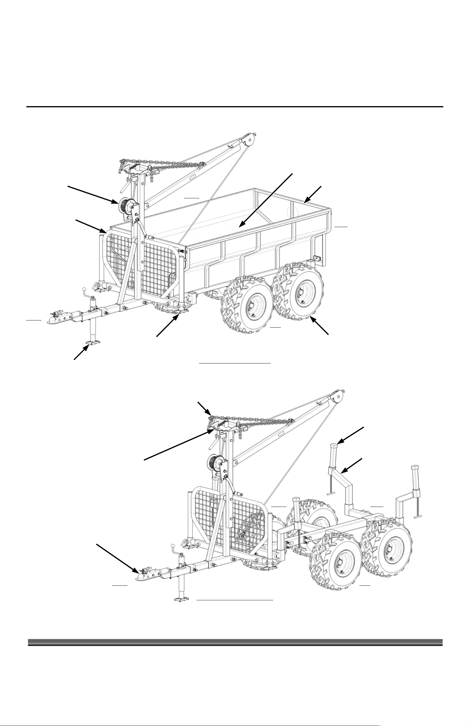
It may be helpful to familiarize yourself with the features of your DR VERSA TRAILER as shown in Figure 1 before beginning these
procedures. If you have any questions at all, please feel free to contact us at www.DRpower.com.
DR VERSA TRAILER Features
Removable Dump Bed
Removable Front and Rear Tailgates Lifting Winch
Right
Operator Guard
Front
Trailer Jack
djustable Stabilizer(s)
Dump Bed Configuration
Left
Rear
Pneumatic Tire(s)
2 inch Ball Coupler on
Pivoting Hitch Arm
djustable Chains and Boom
Boom Swivel
Log Cradle Extension(s)
Log Cradle(s)
Rear
Right
Left
Front
Log Hauling Configuration
Figure 1
6 DR®VERSA TRAILER
Page 7
Specifications
Tire Size 22 x 11-10
Trailer Dimensions
133" L x 51" W x 72" H
Operating Weight
Shipping Weight
Shipping Dimensions
680 pounds
760 pounds
82 1/2" L x 44 1/2" W x 26 1/2" H
Unpacking the DR VERSA TRAILER
Due to the weight of the components of the DR VERSA TRAILER, we strongly recommend that you have the help of at least one
other person in unpacking and assembling your new Trailer.
Tools and supplies needed:
x Utility Knife
x Protective Goggles or Safety Glasses
x Gloves
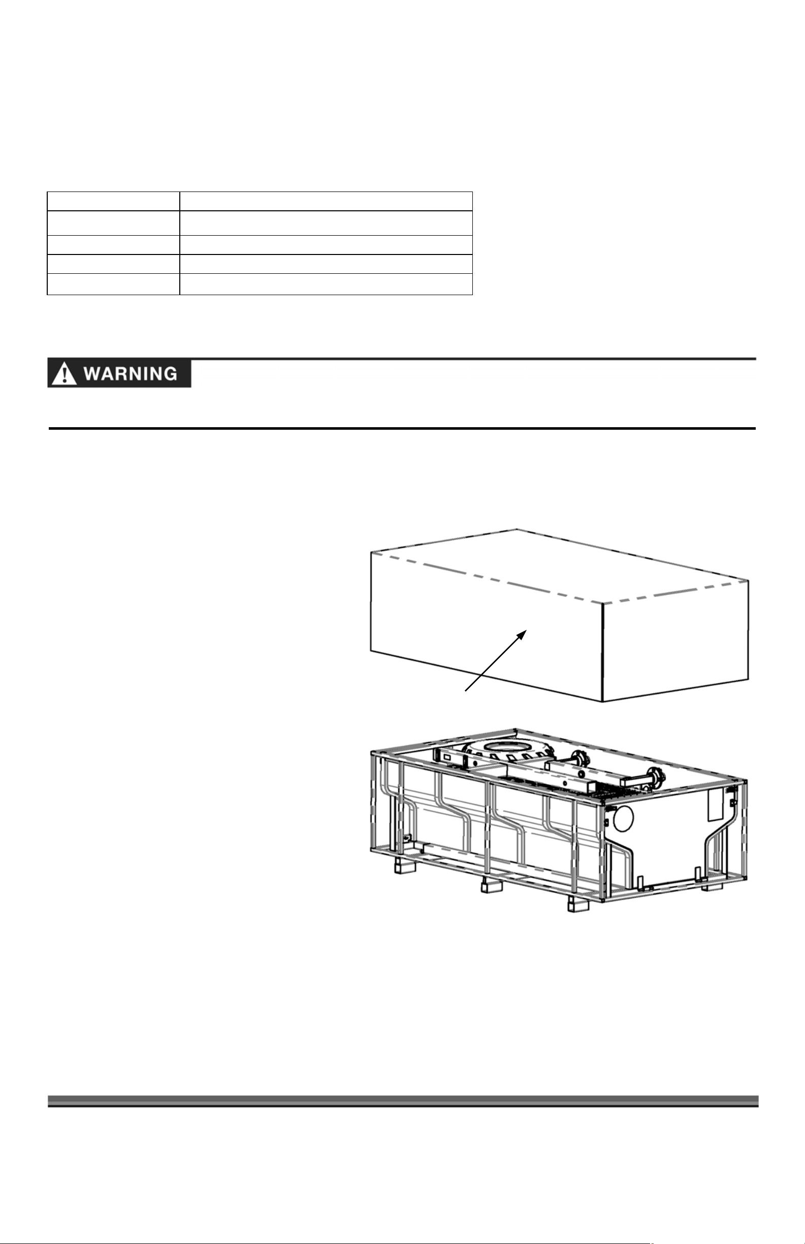
1. Cut the Banding from the Packaging and remove
the Shipping Cover from the Shipping Crate and set
it aside (Figure 2).
2. Remove all of the Parts supplied from inside the
Dump Bed.
3. Using a Utility Knife carefully cut the wrap from the
parts.
4. Compare the contents (Figures 3
9) with the parts supplied list. If you have any
questions, contact 1-800-DR-OWNER (376-9637).
Do not discard your packaging material until you
are fully satisfied with your new DR VERSA
TRAILER, as you will need it if you decide to return
your Trailer.
&
4 on pages 8 &
Shipping Cover
Figure 2
CONTACT US AT www.DRpower.com 7
Page 8
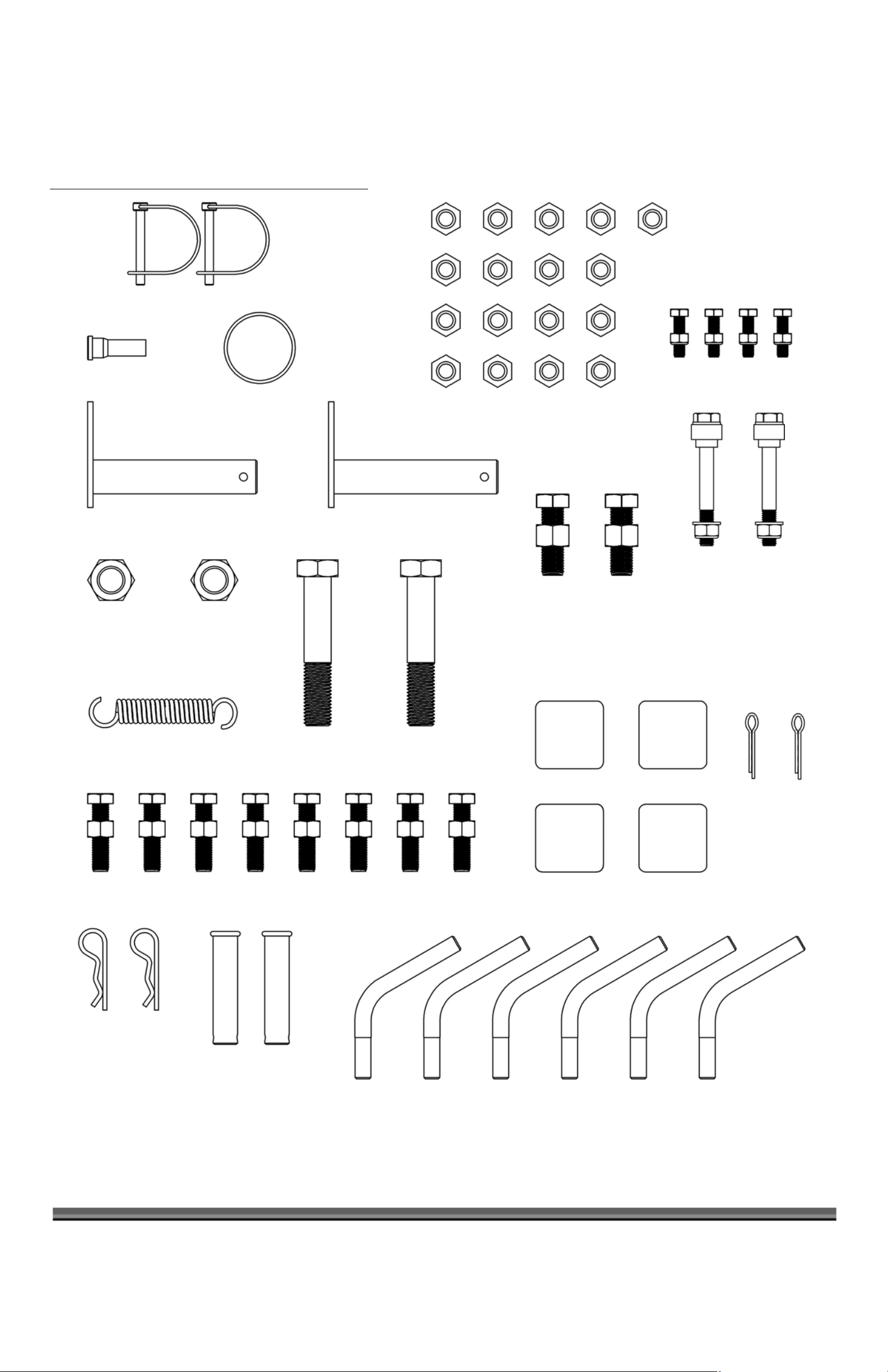
The Parts shown here are included in the Hardware Kit Bag
(2) Safety Snap Pin (30275)
Wheel Stud (29960)
(2) M20 Lock Nut (27720)
Wheel Dust Cap
(29961)
(2) Axle Pivot Pin (30244)
(4) M8 Bolt x 30mm (30245)
(4) M8 Lock Nut (30246)
(17) Lug Nut (29978)
(2) M10 Bolt x 90mm (30251)
(2) Tow Hitch Spacer (30284)
(2) M10 Lock Nut (30249)
(2) M16 Bolt x 50mm (30238)
(2) M16 Hex Nut (30237)
Pivot Lock Spring (30257)
(2) Hitch Clip Pin
(16003)
(2) Dump Bed Pin
(2) M20 Bolt x 110mm (27719)
(8) M12 Bolt x 50mm (30239)
(8) M12 Hex Nut (30240)
(27722)
(2) Cotter Pins
3/16" x 2-1/2"
25311
(4) Box Tubing Cap (29968)
8 DR®VERSA TRAILER
(6) Stabilizer Lock Handle (27733)
Figure 3
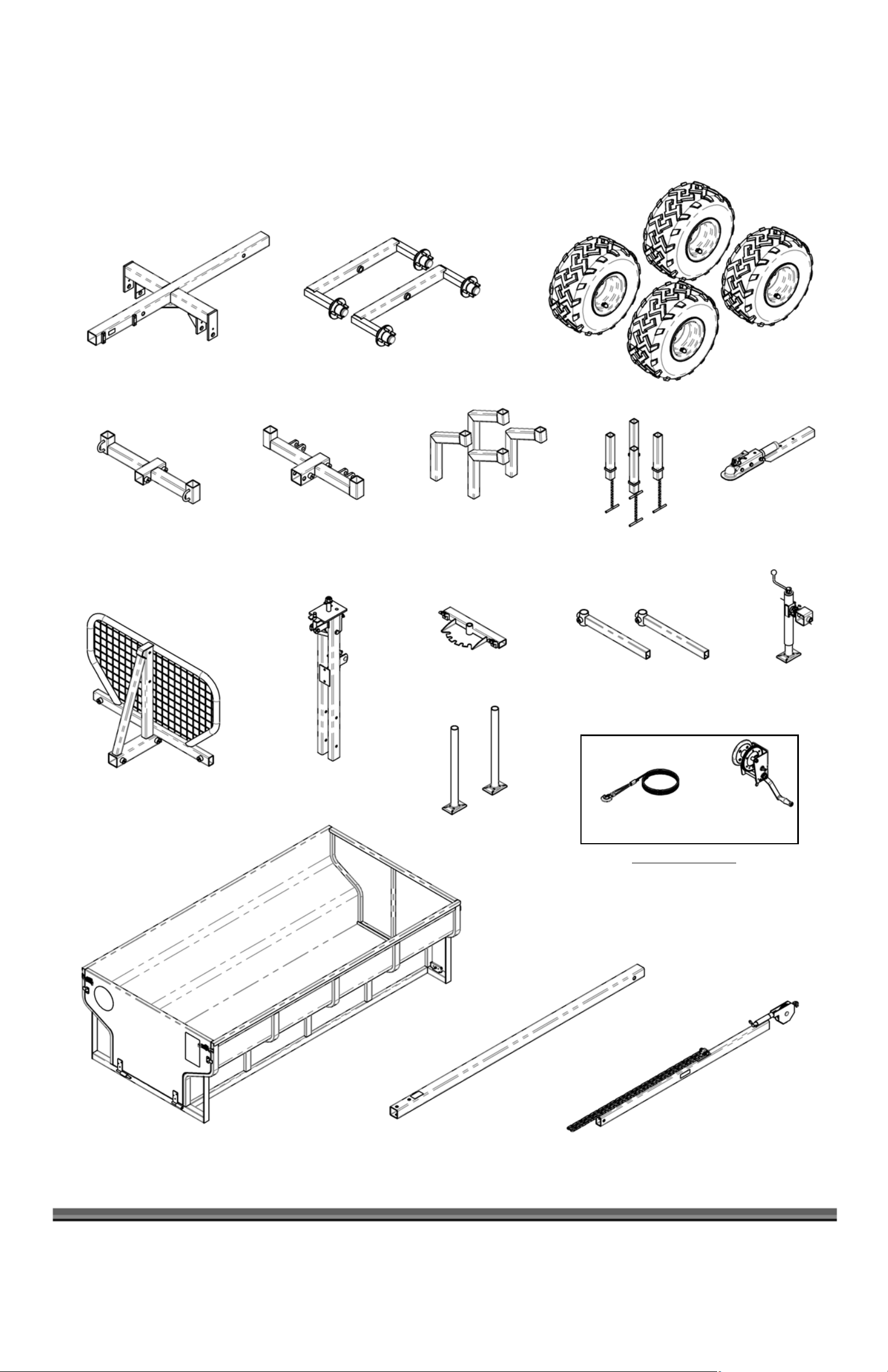
Page 9
/
(
(
Main Frame (29957)
Front Bed Support
(29965)
(2) Axle and Hub Assembly (29958)
Rear Bed Support (29969)
(4) Log Cradle (29966)
Crane Pivot Lock
(299731)
(4) Wheel and Tire Assembly (29964)
Pivoting Tow Hitch
(4) Log Cradle Extension
(29967)
(2) Stabilizer Bracket (277151) Trailer Jack
(30270)
277181)
Operator Guard (29971)
Vertical Crane Support
w/Pivot Handle (30268)
Manual Winch w/Cable (30267) (2) Stabilizer Leg (27716)
Shipped Separately
Tow Bar w
Dump Bed w/Tailgates (30266)
Figure 4
Labels
30271)
Crane Boom w/Chains
and Labels (30269)
CONTACT US AT www.DRpower.com 9
Page 10
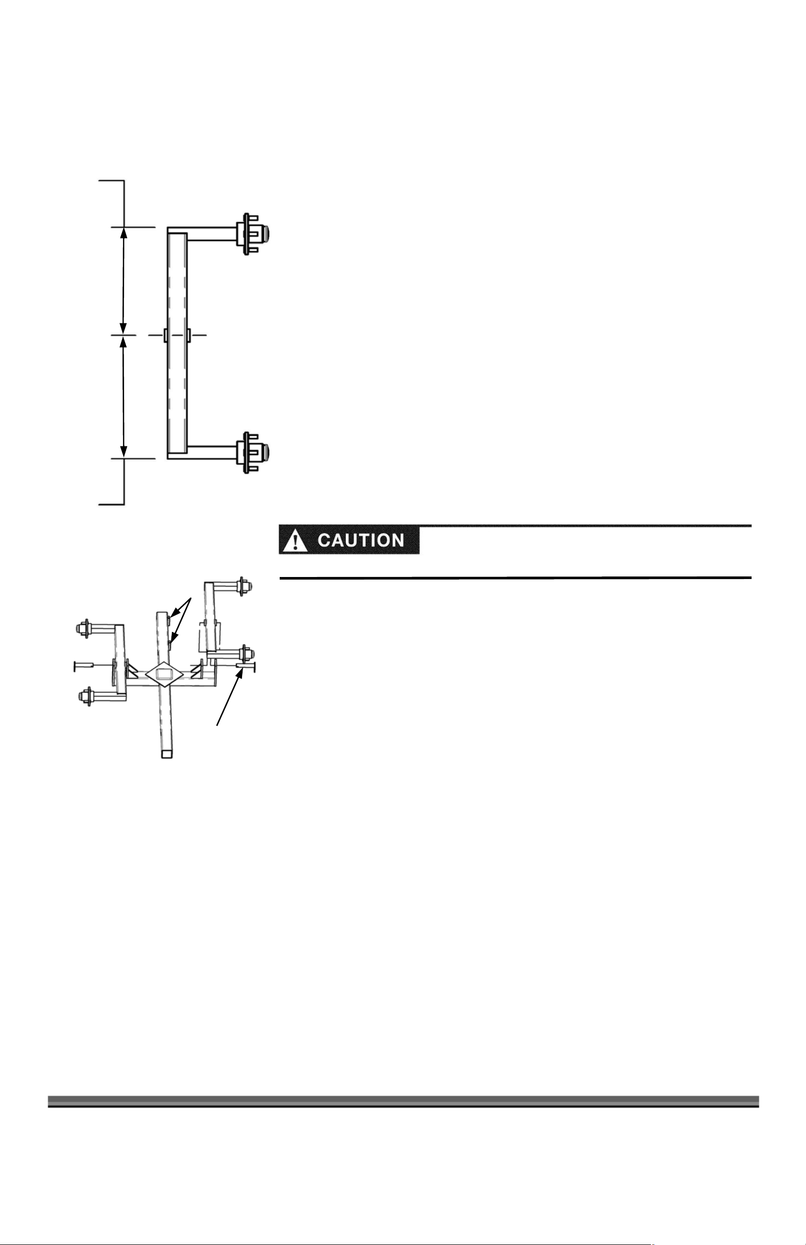
NOTE
13-1/2"
A
15-1/2"
Figure 5
Installing the Wheels and Tow Bar to the Main Frame
Tools Needed:
x Two Adjustable Wrenches capable of tightening a 30mm or 1-1/2" Bolt Head.
x 13mm Wrench required (12, 18, & 30mm Wrenches optional if two Adjustable
Wrenches are available)
x Needle Nose Pliers
x 21mm Socket required (12, 18, & 30mm Sockets optional if Adjustable Wrenches
available)
x Tape Measure
x 5" Socket Extension
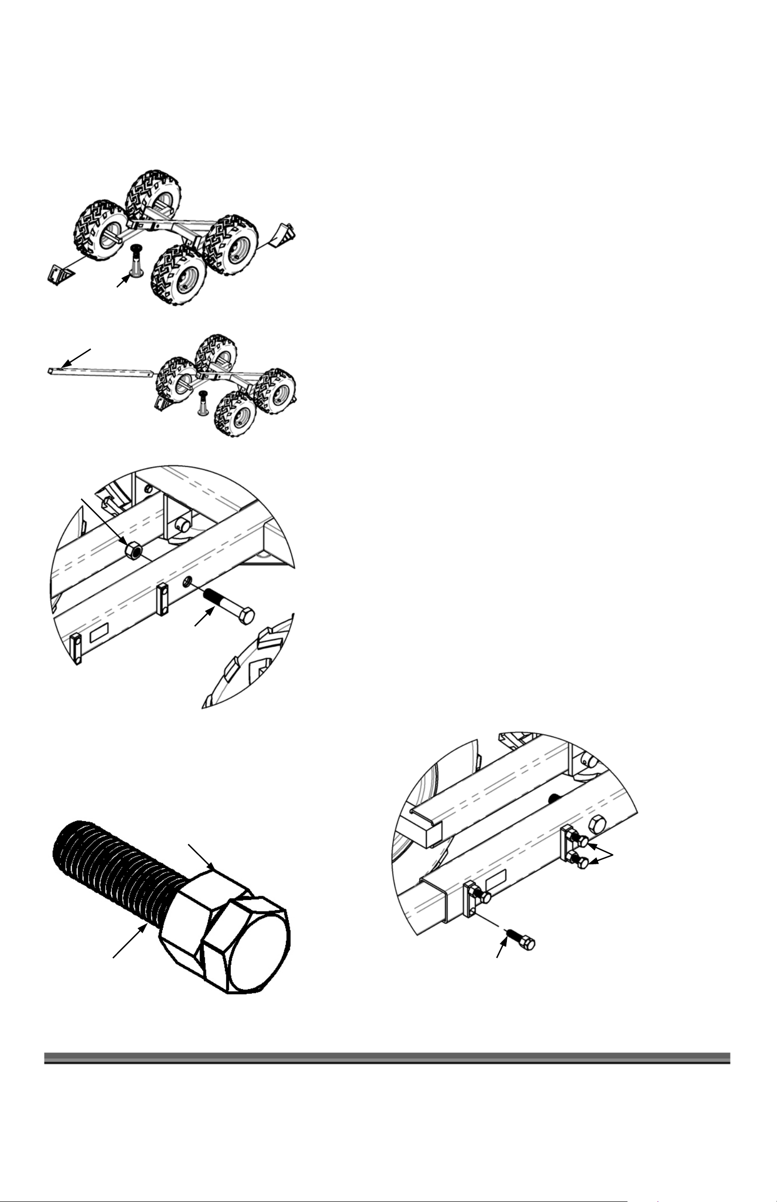
1. Measure the Axles to determine the correct orientation for installation on the
Trailer. The longer portion of the Axle (Figure 5) should face the Front of the
Trailer.
: The Front of the Trailer has the two rectangular Bosses welded to the side of the
Trailer.
2. Turn the Main Frame upside down. Install the Axles to the Main Frame by
inserting the Axle Pivot Pins, with the Tab facing downwards, from the outside of
the Main Frame through the Axles. Align the Hole through the Tab on the Pin
with the Hole in the Main Frame and repeat for opposite side (Figure 6).
Bosses
Figure 6
Take care not to Pinch hands or Fingers when installing the Axles and Axle Pivot Pins.
NOTE: It is easier to install the Axle Pivot Pins by first placing the Axle(s) between the
mounting plates, then picking up one end of the Axle, while allowing the other to rest on the
ground. This will take some of the weight off and allow you to align the holes much easier so
you may insert the Axle Pivot Pin(s).
xle Pivot Pin(s)
10 DR®VERSA TRAILER
Page 11
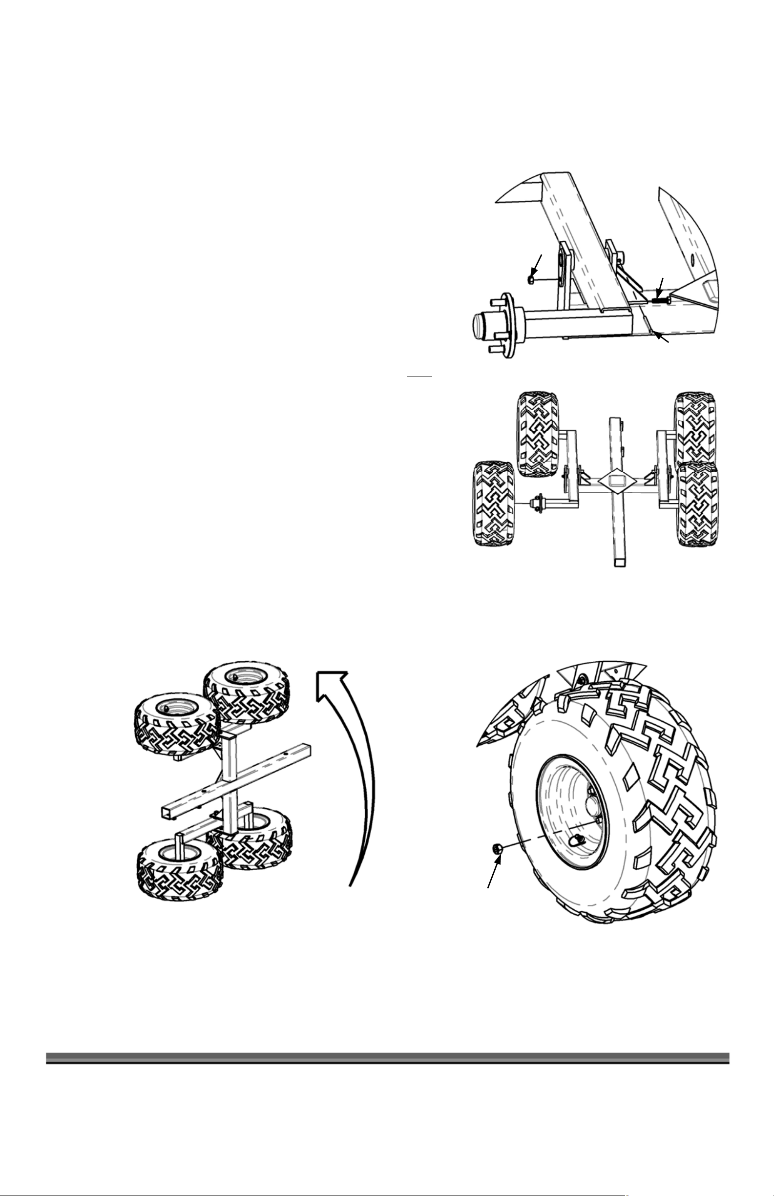
3. Insert a M8 x 30mm Mounting Bolt (Figure 7) from the inside of the
Frame and through the Tab on the Axle Pivot Pin. Install a M8 Flange Nut
and tighten with a 12mm Socket, holding the Bolt with a 13mm Wrench.
4. Insert a Cotter Pin (Figure 7) through the Left and Right Axle Pivot Pins
and bend the legs over with Pliers.
5. Install the Left and Right wheels on the Axles with the supplied Lug Nuts
until snug with a 21mm Socket and 5" Extension; they will be torqued
later.
NOTE: The Wheels are marked L (Left) and R (Right), as they are directional
Tires. Since the Main Frame is upside down, the Left Wheels should be
installed on the Right Side and the Right Wheels on the Left Side (Figure
8). Make sure the Valve Stem(s) face outwards. The Lug Nuts must
be
installed with the tapered side of the Nuts facing the Hub of the Wheel
(Figure 9).
6. Turn the unit over with the assistance of at least one other person.
M8 Nut
M8 x 30mm
Bolt
Cotter Pin
Figure 7
Front
NOTE:
The easiest way of turning the unit over is to lift the two Wheels on the
Right Side of the Trailer while pivoting over the Wheels on the Left Side
(Figure 10).
Right Left
Figure 8
Figure 10
Tapered side
facing in
Figure 9
CONTACT US AT www.DRpower.com 11
Page 12
J
J
ack Stand
f
7. Place a Jack Stand under the front of the Main Frame, which should
naturally be tipped backwards (Figure 11). Also place one wheel chock in
front of one of the Front Wheels and one wheel chock behind one of the
Rear Wheels to ensure the Trailer will not roll on you during assembly.
8. Slide the Tow Bar (with the Warning Label on top) into the Main Frame,
lining up the Mounting Hole with the hole in the Main Frame (Figure 12).
Gently allow the weight of the Tow Bar to force the front of the Main
Frame down onto the Jack Stand.
M20 Lock
Nut
Figure 11
Warning Label
Figure 12
9. Install a M20 x 110mm Bolt and Washer (Figure 13) in the Mounting Hole,
and install a M20 Lock Nut. Tighten with Adjustable Wrenches or a 30mm
Socket and an Adjustable Wrench.
10. Back the Jam Nuts on the four Retaining Bolts (Figure 14) all the way to
the head of the Bolts.
Note: You will need to back all Jam Nuts off, to the head of the Retaining Bolts for
all hardware shipped in the Hardware kit prior to installation (Figure 14). Be sure
to tighten the Bolt first and then secure it by tightening the Jam Nut.
11. Insert the four Retaining Bolts into the Bosses on the left side of the Main
Frame and securely tighten with an 18mm Socket (Figure 15).
12. Screw in the Jam Nuts against the Boss and tighten with an 18mm
Wrench.
M20 x 110mm Bolt
Figure 13
am Nut
Final position o
the Jam Nut(s)
Retaining Bolt
Figure 14
12 DR®VERSA TRAILER
Retaining Bolt(s)
Figure 15
Page 13

Attaching the Front Bed Support, Operator Guard, Trailer Jack & Pivoting Tow Hitch w/Coupler
Tools Needed:
x 17mm, 18mm, and 24mm Wrenches or an Adjustable Wrench
x 16mm Socket
x Tape Measure
1. Slide the Front Bed Support onto the Tow Bar with the Mounting Bosses
facing the Left, 9-1/2" from the end of the Main Frame (Figure 16).
2. Install and tighten two M12 x 50mm Bolts and Jam Nuts with an 18mm
Socket for the Bolts and an 18mm Wrench for the Nuts (Figure 17).
3. Slide the Operator Guard onto the Tow Bar with the Mounting Bosses
facing to the Left, 26" from the end of the Main Frame (Figure 16).
4. Install two M16 x 50mm Bolts with M16 Jam Nuts (Figure 18) into the
Operator Guard Bosses on the Right Side and tighten the Bolts with a
24mm Socket and the Jam Nuts with a 24mm Wrench or Adjustable
Wrench.
5. Slide the Trailer Jack 10-1/2" onto the Tow Bar (Figure 16), with the
Mounting Boss facing the Left side of the Trailer. Tighten the M16 x 50mm
Trailer Jack Bolt and M16 Jam Nut with a 24mm Socket and Wrench.
NOTE: You may need to loosen the Bolt installed in the Trailer Jack prior to
installation to be able to slide the Jack onto the Tow Bar.
9-1/2"
Mounting
Bosses
26"
Mounting
Bosses
10-1/2"
Figure 16
M16 x 50mm Bolt
w/Jam Nut
M12 x 50mm Bolt(s)
w/Jam Nut(s)
Figure 18 Figure 17
CONTACT US AT www.DRpower.com 13
Page 14

Pivoting Tow Hitch
6. Install the Pivoting Tow Hitch (Figure 19) into the Tow Beam with the Swivel
facing upward.
7. Install two M12 x 50mm Bolts and Spacers, with the smaller diameter
Shoulder(s) down, (Figure 20) through the Tow Bar and Pivoting Tow Hitch.
Install a Flat Washer, Lock Washer, and M12 Lock Nut on each Bolt and
tighten with a 16mm Socket while holding the Nut with a 17mm Wrench.
Swivel
Figure 19
M12 x 50mm Bolt(s)
and Spacers
Flat Washer(s)
Lock Washer(s)
M12 Lock Nut(s)
Attaching the Adjustable Stabilizer Legs and Arms
Watch your feet when lowering the Stabilizer Legs.
1. Slide the Stabilizer Legs (Figure 21) all the way into each Adjustable
Stabilizer Arms and screw in and tighten the Locking Handles (Figure 22) to
hold the Legs in place.
2. Slide the Adjustable Stabilizer Arms all the way into the Operator Guard and
screw in two Locking Handles to hold the Arms in place (Figure 23).
3. Loosen the Locking Handles holding up the Stabilizer Legs until they drop to
the ground and retighten them. Remove the Jack Stand from under the
Trailer.
Figure 20
Stabilizer Arm
Locking Handle(s)
Stabilizer Leg
Figure 21
14 DR®VERSA TRAILER
Figure 22
Locking Handles
Figure 23
Page 15

Attaching the Crane
Tools Needed:
Lock Nut, Flat
Washer and
Tabbed Washer
Boom Pivot
x 22mm and 17mm Wrench
M10 Lock Nut
x 21mm, 16mm and 30mm Sockets
x Large Adjustable Wrench
1. Remove the Lock Nut, Flat Washer, and Tabbed Washer from the
top of the Crane (Figure 24) along with the Pivot Lock Handle by
removing the M10 x 1.75mm Bolt and M10 Lock Nut with a 16mm
Socket for the Bolt and a 17mm Wrench for the Nut.
2. Remove the two M14 x 140mm Bolts and M14 Nuts from the
Crane with a 21mm Socket for the Bolt and a 22mm Wrench for
the Nut.
3. Install the Boom Pivot (Figure 25) on top of the Crane with the
Mounting Boss pointing up and re-install the Tabbed Washer 1
Flat Washer 2
nd
, then the Lock Nut. Do not tighten yet.
st
,
4. Lay the Crane on the Operator Guard, with the Diagonal Support
of the Operator Guard between the two legs of the Crane (Figure
26). Snug the Lock Nut on the Boom Pivot using a large
Adjustable Wrench, or a 30mm Socket making sure the Tabbed
Washer is facing downward. Back the Nut off ½ turn, to make
sure the Boom Pivot rotates freely.
5. With the assistance of another person, rotate and lift the Crane to the
vertical position (Figure 27). Install two M14 x 140mm Bolts, from the Left
side, through the Crane and Operator Guard and attach the M14 Lock
Nuts. Tighten using a 21mm Socket on the Bolt and a 22mm Wrench on
the Nut (Figure 27).
6. Install the Pivot Lock Handle in the orientation shown in Figure 27 with the
hardware removed in Step 1 of this section.
Pivot Lock
Handle
M14 Nut
M10 Bolt
M14 Bolt
Figure 24
Figure 25
Lock
Nut
7. Install the Extension Spring on the Boom Pivot Handle. Hook one end
around the Handle and the other end through the Tabbed Washer (Figure
28) on the Boom Pivot. Ensure that the Spring is properly seated in the
Groove on the Boom Pivot Handle.
Extension Spring
Tabbed Washer
Groove
Figure 26
M14 Lock
Nut(s)
Boom Pivot
Handle
Figure 28
Mesh Guard
Hidden for Clarity
Figure 27
CONTACT US AT www.DRpower.com 15
M14 x 140mm
Bolt(s)
Page 16

Boom Swivel
Bracket
Attaching the Winch and Boom
Tools Needed:
x 17mm and 22mm Wrench
x 17mm, 21mm, and 24mm Socket
x 5" Long Socket Extension
x Adjustable Wrench
NOTE: Before installing the Winch and Boom to your DR VERSA TRAILER, follow the
instructions shipped with your Winch to properly install the Handle and Cable. You may
want to install the Cable after the Winch has been installed to your Trailer.
1. Remove the Boom Swivel Bracket (Figure 29) using a 24mm Socket and
Adjustable Wrench.
2. With the assistance of a second person, install the Winch (Figure 30), with the
Crank Handle facing to the Left, using two M10 x 25mm Bolts, and Lock Nuts.
Tighten using a 17mm Socket w/Extension and Adjustable Wrench and reinstall
the Boom Swivel Bracket.
3. Remove the Cable Guide (Figure 31) using a 21mm Socket on the Bolt and a
22mm Wrench on the Nut.
Winch
M10 Lock
Nut(s)
Figure 29
4. Pull the Winch Hook up through the Cable Guides on the Crane (Figure 32) and
M10 Bolt(s)
reinstall the Cable Guide with the Cable on Top of the Guide (Figure 33). Make
sure that Guide is free to rotate.
Winch Hook
Cable Frame
Figure 30
Cable Guide
Figure 31
16 DR®VERSA TRAILER
Figure 32
Cable Guide
Figure 33
Page 17

5. Reinstall the Boom Swivel Bracket and hardware, and then remove the Hitch
Clip Pin and Pin from the Bracket (Figure 34).
6. Install the Boom to the Boom Swivel Bracket with the Chain Attachment
Bracket on the Boom pointing up (Chains not shown for clarity), using the
Hitch Clip Pin and Pin that was removed in step 5 (Figure 35).
7. Have a second person lift the Boom then hook the fourth link of the Left and
Right Chains into the Boom Pivot (Figure 36) and insert a Hitch Clip in the
Boom Pivot on both sides to secure the Chains (Figure 36).
8. With the assistance of another person, pull the Winch Cable forward, while
the other person cranks the Winch in reverse to let the Cable out and loop it
around the Rear Cable Support. Thread the Cable in horizontally between
the two Hooks (Figure 37) to hold it in place.
Boom Swivel Bracket
Figure 36
Rear Cable Support
Hitch Clip
Boom Pivot
Pin
Hitch Clip Pin Pin
Figure 34
Boom Swivel Bracket
Hitch Clip Pin
Figure 37
Figure 35
CONTACT US AT www.DRpower.com 17
Page 18

Installing the Rear Bed Support and Attaching to a Tow Vehicle
Main Frame
Tools Needed:
x 18mm and 30mm Socket
x 18mm Wrench
Boss
x Adjustable Wrench
Rear Bed Support
x 1/2" Drive Torque Wrench
x 5" Long 1/2" Drive Socket Extension
x 21mm 1/2" Drive Socket
1. Slide the Rear Bed Support (Figure 38) onto the Main Frame with the
Bosses facing Left.
2. Line up the through Hole in the Rear Support and Main Frame and install
Figure 38
M20 Lock Nut
M20 x 110mm
Bolt
the M20 x 110mm Bolt (Figure 39) through the Rear Support and Main
Frame and secure with the M20 Lock Nut and tighten with a 30mm Socket
and Adjustable Wrench.
3. Install two M12 x 90mm Bolts w/Jam Nuts (Figure 40) in the Rear Support
and tighten the Bolts then the Jam Nuts using an 18mm Socket and 18mm
Wrench.
Figure 39
M12 x 90mm Bolt(s)
w/Jam Nut(s)
x Make sure your 2" Hitch Ball is correctly tightened to the Receiver and that
the Receiver is properly connected to your Towing Vehicle. A loose Ball or
Receiver can result in the Trailer detaching from the Tow Vehicle during use.
x A worn, corroded, cracked, or otherwise damaged Hitch Ball can fail while
towing. Always inspect your Ball before attaching to your Trailer.
x Always use a 2" Hitch Ball with your Trailer.
x Never operate your Trailer if the Coupler is not locked and the Safety Snap
Pin is not installed.
x When the Trailer’s Coupler is connected to the Ball and is in the locked
position, rock the Tow Bar up and down as well as side-to-side to make sure
the Ball is tight to the Coupler. A properly fastened and locked Coupler will
raise the rear of the Tow Vehicle when it is pulled upwards without coming
off of the Ball.
4. Attach the Trailer to your Tow Vehicle using a 2" Ball, making sure to
properly latch the Coupler, and locking it with the supplied Safety Snap Pin
(Figure 41 on page 19). After the Trailer is attached, remove the Wheel
Chocks.
Figure 40
18 DR®VERSA TRAILER
5. Loosen the Locking Handles for the Stabilizer Legs and raise them to the
highest position for towing. Re-tighten the Locking Handles and rotate the
Trailer Jack to the Tow position (Figure 42 on page 19).
6. Torque the Lug Nuts on each Wheel to 85-90 ft-lbs using a Torque Wrench,
a 5" Extension and 21mm Socket.
Make sure all Nuts and Bolts are tight. Inspect all Hardware on your Trailer
before proceeding any further.
Page 19

Inserting the Log Hauling Extenders
J
NOTE: If you wish to use the Trailer in the Log Hauling configuration initially,
please follow these steps, if not please skip to the next section that covers
installing the Dump Bed.
1. Insert the Log Cradles (Figure 43), with the angled portion of the Cradles
facing outwards.
2. Insert the Log Cradle Extensions by first passing the Chain through the
Square opening(s) of the Log Cradles (Figure 43).
3. Install the Log Cradle Extension Caps (Figure 43).
Lever Down to
Lock on Ball
Safety Snap Pin
Figure 41
Stabilizer(s) in
Tow Position
ack in Tow Position
Figure 42
Figure 43
Cap(s)
Extension(s)
Log
Cradle(s)
CONTACT US AT www.DRpower.com 19
Page 20

Removing the Blue Plastic Protective Film and Installing the Dump Bed
Latch
Tailgates
Figure 44
Tools Needed:
x Utility Knife
x Protective Goggles or Safety Glasses
x Gloves
x The Bed of the Trailer is very heavy and must be lifted out of the Shipping
Crate and on to the Trailer by at least
two adults.
x Always be aware of where your Hands and Feet are positioned as they can be
crushed if you loose your grip while lifting the Bed from the Shipping Crate.
x Never allow children or pets to play around you, the Bed, Shipping Crate, or
Trailer when you are performing these steps.
1. Remove the Bed from the steel-shipping Crate with the assistance of at least
one other person by lifting the Bed straight up, and out of the Crate by the
Tailgates. Make sure all four Latches on the Tailgates are properly latched
(Figure 44) before lifting the Bed out of the Crate and placing it on the
ground.
Panel(s)
U-Bolt
Pivot Support(s)
Figure 45
2. To remove the Blue Plastic Protective Film from the Inside and Outside of
the Bed, use your Fingernail, or the point of a Utility Knife to peel up one
end of the plastic at the edges of the Bed and begin to peel off the Film.
3. With the assistance of at least
one other person, turn the Bed over onto its
top, to remove the Blue Plastic Film from the exterior and underside of the
Bed. Use the Utility Knife to cut around the Black Frame of the Trailer for
the individual panels (Figure 45). Once you have cut around the individual
panels, use the point of the Knife to begin peeling at the edge.
4. With the assistance of at least
one other person, turn the Bed back over and
place the Bed on the Trailer in the orientation shown in Figure 46, with the
U-Bolt at the front of the Trailer and the Dumping Pivots on the Bed placed
between the Pivot Supports on the Rear Bed Support.
NOTE:
It is recommended to lift the Bed from the Sides to walk the Bed onto the
Trailer. It is easier to install the Bed without the Log Cradles and Extensions
inserted into the Frame. These are also unnecessary when the Bed is installed.
5. Align the Holes though the Dumping Pivots on the Bed with the ones on the
Rear Bed Support and install the two Pivot Pins and Hitch Clips (Figure 47
on page 21).
6. Attach the Hook from the Winch to the U-Bolt in the Bed (Figure 48 on page
21).
Figure 46
20 DR®VERSA TRAILER
7. Check and adjust the Tire Pressures to 25-28 PSI prior to use.
8. CONGRATULATIONS! Your DR VERSA TRAILER is now ready to use! See
the next Chapter for operating suggestions and tips.
Page 21

Pivot Pin(s) Hitch Clip(s)
Figure 47
Winch Hook
Figure 48
U-Bolt
CONTACT US AT www.DRpower.com 21
Page 22

Chapter 3: Operating The DR VERSA TRAILER
This chapter covers the basic operation procedures for your new DR VERSA TRAILER. It may be helpful to better familiarize
yourself with the features of your Trailer by reviewing Figure 1 in Chapter 2 before beginning the steps outlined in this chapter.
Read and understand the warnings listed in “Chapter 1 General Safety Rules” before operating the DR VERSA TRAILER.
Before You Begin
x Visually check the Winch Cable for any frays or other damage each time you use the Trailer.
x Inspect the Winch for smooth operation, no binding, pinching or crimping of the Cable.
x Assure that the Tires are properly inflated.
x Assure that the Wheel Lug nuts are properly torqued.
x Assure that the Trailer is securely fastened and properly adjusted to your Tow Vehicle using a 2" Ball and properly latching and
locking the Tow Hitch with the Safety Snap Pin.
x Assure that all hardware is tight.
x Inspect the Crane and Boom for any damage or bending.
Loading the Trailer
x Never load, or unload the Trailer if it is not securely attached to a suitable Tow Vehicle.
x Never load, or unload the Trailer if it is on, or near a slope as the Trailer may tip, or drag the Tow Vehicle down the slope.
x Always securely set the Parking Brake and ensure the Tow Vehicle is in Park before dismounting to load, or unload the Trailer.
x When loading the Trailer it is best to evenly distribute the weight front to rear to provide the proper Tongue Weight. If too much
weight is concentrated to the Rear of the Trailer you will cause a negative Tongue Weight, which could lift the rear of the Tow
Vehicle, which could cause you to lose control during Towing. Adversely, too much weight at the front of the Trailer can cause
too great of a Tongue weight on the Trailer and Lift the front of the Tow Vehicle off the ground, diminishing your ability to
effectively turn and stop.
x Load the Weight evenly side to side to avoid overloading the Tires.
x Always keep the Center of Gravity low to improve the stability of the Trailer.
x Always secure any load placed in, or on the Trailer to limit shifting of the cargo as this can cause loss of control of the Trailer
and Tow Vehicle. Always use properly sized Straps, Ropes, etc.
x Always follow the Towing instructions and ratings found in your Tow Vehicle’s Manual. Familiarize yourself with the Gross
Vehicle Weight Rating (GVWR) of your Tow Vehicle, which is the total weight of the load you put in, or on the Trailer, plus the
empty weight of the Trailer itself and never exceed this rating.
x Never use the Trailer to transport People, Containers of Hazardous, Flammable, or Explosive Substances.
x If you are using the Dump Bed with the Tailgates installed, always make sure the Latches are properly adjusted and locked.
Before loading the Trailer, extend the Outriggers no more than 15" outwards
from the end of the Operator Guard (Figure 49) and lower the Adjustable
Stabilizer Legs to the ground and tighten the Locking Handles. Once you have
finished loading the Trailer, raise the Adjustable Stabilizer Legs and retract the
Outriggers for travel.
15" 15" Figure 49
22 DR®VERSA TRAILER
NOTE: If you are loading material into the Bed that you wish to dump, make sure
the Winch Hook is properly secured to the U-Bolt inside the Bed (Figure 48, on page
21).
Page 23

Using the Dump Bed
x Never stand in, or under the Bed when dumping material from the Bed.
x Never place anything under the raised bed and always ensure that no other adults, children, or pets are near, or around the Bed
when lowering it back into place.
x Never load more than 650 lbs of material into the Bed if you are intending to dump it.
1. The Dump Bed may be used to haul and dump a number of things from dirt, rocks, stones and logs, to name a few. To dump
material from the Bed of the Trailer, remove the Rear Tailgate.
NOTE: To remove the Tailgate(s) release the Latches on the Tailgate by pulling the Red Handles of the Latches away from the Tailgate.
Pivot the Tailgate down and then push the Tailgate to the Left to uncouple the Hinge (Figure 50).
2. Once the Tailgate has been removed, use the Winch to raise the Bed to dump the material out.
NOTE: The Chains for the Boom need to be adjusted to the ideal length for the Dumping of the Bed. Adjust the length of the Chains so
the 10th link of the Chain (from the end of the Chain) is captured and securely pinned in place, with the supplied Hitch Clips, on
the Boom Pivot. It is recommended to have the assistance of one other person to support the weight of the Crane while you
adjust the length of the Chains individually. Remove one Hitch Clip, adjust the Chain, then re-seat the Chain in the Retainer on
the Boom Pivot and re-insert the Hitch Clip (Figure 51). Repeat for the other Chain to have the Boom centered on the Trailer
and ready for dumping.
Hitch Clip
Figure 50
Figure 51
CONTACT US AT www.DRpower.com 23
Page 24

f
Using the Winch and Boom to Load Logs onto the Trailer
x Always stand on the Crank Handle side of the Winch (Figure 51), never directly in line with the Winch Cable, and always behind
the Operator Guard! If the Winch Cable is kinked, frayed, or otherwise damaged, do not use it. Replace the Cable immediately.
x Always make sure there are more than 6 complete wraps of the Cable around the Drum of the Winch. Never extend the Cable o
the Winch past this point, as it will compromise the strength of the Winch and Cable.
x Never lift more than 440 lbs with the Winch.
x When using the Winch to load a Log or other item on to the Trailer, or into the Bed, never lift it higher than the Frame, or the
Bed of the Trailer (if installed). Keep the weight as low as possible.
x When lifting an item on to the Trailer, or into the Bed (if installed), never stand under or near the item being lifted. Always
make sure that any bystanders, children, or pets are at least 30 feet away and are behind the Operator Zone.
1. Remove the Bed of the Trailer by removing the Pivot Pins and Hitch Clips that attach the Bed to the Trailer. Slide the Bed to
the rear of the Trailer and either stand it up on end, on level ground, or lay it down.
Never allow other adults, children, or pets to play around a Bed that is stood up on end as they could contact it and knock it over.
If you are intending to store the Bed stood on end, secure it with adequate ropes or straps to ensure it cannot easily topple.
Maximum Boom Travel
Operator Zone
2. Use the Winch to unload the Logs by rotating the Boom to either side of
the Dump Bed by using the Boom Swivel (Figure 1 on page 6). To
rotate the Boom, push the Pivot Lock Handle inwards until it pivots out
to clear the Boom Pivot. Rotate the Crane in the desired direction and
release the Pivot Lock Handle so it seats itself back into one of the
Locking Detents on the Boom Pivot. Refer to Figure 52 for the
maximum Boom travel and Operator position.
3. Extend the Outriggers and Stabilizer Legs as described in Loading the
Trailer on page 22 and use the Winch with a Choker Chain (sold
separately) to drag, or lift Logs on to the Trailer. Be sure to securely
attach the Choker Chain to the Log by wrapping the Chain tightly
around the Log once, then through the Ring on the Choke Chain.
Connect the Winch Hook to a Chain Link on the Choker Chain that is at
least 2 Links through the Ring of the Choker Chain. The Choker Chain
should tighten itself around the Log as you begin to slowly pull the Log
toward the Trailer with the Winch.
Using the Log Cradles and Extensions
1. Remove the Dump Bed by performing steps 4 & 5 on page 20 in the
reverse order.
24 DR®VERSA TRAILER
Figure 52
Figure 53
2. Slide the four Log Cradles into the Slots in the Main Frame (Figure 43
on page 19). Depending on the height of the Logs in the Trailer, you
may want to use the Log Cradle Extensions by sliding them into the Log
Cradles (Figure 43 on page 19).
Adjusting the Tailgate Latches
Overtime you may need to adjust
your Tailgate Latches. To do so,
open the Latch (Figure 53) and
thread the Latching Arm inwards,
or outwards to adjust the length of
the Latching Arm (Figure 54).
Figure 54
Page 25

Chapter 4: Maintaining The DR VERSA TRAILER
Regular maintenance is the way to ensure the best performance and long life of your Trailer. Please refer to this manual for
maintenance procedures.
Regular Maintenance Checklist
x Before inspecting, or performing any Maintenance make sure the Tow Vehicle is properly Parked on Level Ground and the
Wheels of the Trailer are Chocked.
x Never position yourself, or anyone else under the Bed when it is raised.
PROCEDURE BEFORE
EACH USE
Check General Equipment Condition
Check the Condition of the Winch Cable for any wear
Inspect the Chains for any deformed or broken links
Inspect the Boom and Crane for any bends, cracks, or signs of fatigue
Inspect the rollers and pulleys for cracks, breakages, bends or other severe signs of wear
Inspect the Tow Hitch Coupler and the 2" Ball
Lubricate the Winch (per the Winch instructions, shipped with the Winch)
Check all Hardware to ensure everything is properly tightened
Check Tire Pressure
Torque Wheel Lug Nuts
Grease the Axle Pivot Pins, Swivel of the Tow Hitch, the Receiver and the 2" Ball
Grease the Wheel Bearings
NOTE: If the Trailer is submerged to the Wheel Bearings, or is exposed to large amounts of
Debris, grease the Wheel Bearings sooner to avoid damage.
S
S
S
S
S
S
S
S
S
S
E
VERY 6
ONTHS
M
S
S
CONTACT US AT www.DRpower.com 25
Page 26

Greasing the Tow Ball, Tow Hitch, and Grease Fittings
&
Figure 55
Grease Fitting
Grease Fitting
Your DR VERSA TRAILER'S Wheel Bearings were greased at the Factory. Prior
to using your Trailer for the first time, you need to lubricate the Axle Pivot Pins,
Swivel of the Tow Hitch, the Tow Hitch Coupler, and the 2" Ball you will be
using. You should also periodically lubricate the Axle Pivot Pins, Tow Hitch
Swivel, Tow Hitch Coupler, and 2" Ball to reduce wear and rust on these
components.
Tools and Supplies Needed:
x Flexible hose grease gun
x Lithium grease
x Clean cloth
1. Wipe all dirt, etc., from the Grease Fitting(s) with a clean cloth.
2. Apply enough quality general-purpose lithium grease with a hand-pumped
grease gun to each Axle Pivot Pin and Tow Hitch Swivel Zerk Fitting, so a
small amount of Grease comes out of the Fitting(s) (Figures 55
3. Apply the grease to your 2" Tow Ball to reduce friction on the Tow Hitch
Coupler and to help prevent rusting and seizing of the ball to the Coupler.
56)
Figure 56
Grease
4. Apply the grease to the Pivot Pins of the Latch on the Coupler and to the
underside of the Coupler (Figure 57).
TIP: The Tow Hitch is designed to rotate 360° to ease greasing of the underside
of the coupler.
Grease
Side
Figure 57
26 DR®VERSA TRAILER
Underside
Page 27

Wheel and Lug Nuts
x Lug Nuts and Wheel Studs are prone to damage if loose. Lug Nuts are prone to loosening after installation. The deformation
of the Wheel Rim where the Lug Nut seats will cause the Nut(s) to loosen and could result in a Wheel coming off of the Trailer.
Check the Lug Nuts individually for tightness before each use, or after a Wheel has been replaced on the Trailer.
x Inspect the Lug Nuts to ensure all are present and tight before operation. Never operate the Trailer if a Lug Nut is missing, or
is not properly torqued.
x Always torque the Lug Nuts to 85-90 ft-lbs in an alternating pattern.
x Inspect the Wheel Studs for damage. Never operate the Trailer with a damaged or missing Wheel Stud.
x To check the Wheel Bearings of your Trailer, jack the Trailer off of the ground and check the Wheels for side-to-side looseness.
If the Wheels are loose, or Spin with a Wobble, the Bearings must be replaced.
x Before operating the Trailer always check the Tire Pressures of the Trailers Tires with no load in the Bed, or on the Trailer. They
should be adjusted to 25-28 PSI and never in excess of 36 PSI.
x Inspect the Wheels for damage, or bending. Never operate the Trailer if a Wheel is damaged; replace the Wheel immediately.
x Inspect the Tires for damage or cuts. Even if the Tire is not leaking air, damage, or cuts could lead to a blow out when the
Trailer is loaded. Never operate the Trailer if a Tire is damaged; replace the Tire immediately.
x Inspect all Valve Stems of the Tires. If the Valve Stems are damaged, do not use the Trailer; have the Valve Stem(s) replaced, or
replace the Wheel(s) and Tire(s).
x Clear all debris from the area of the Valve Stem(s) before operation to avoid damaging the Stem(s).
CONTACT US AT www.DRpower.com 27
Page 28

Chapter 5: Troubleshooting
Most problems are easy to fix. Consult the Troubleshooting Table below for common problems and their solutions. If you
continue to experience problems, contact us at www.DRpower.com or call toll-free 1-800-DR-OWNER (376-9637) for support.
Shut down the Tow Vehicle Engine and apply the Parking Brake before performing any maintenance procedure or inspection on
the DR VERSA TRAILER.
Troubleshooting Table
SYMPTOM POSSIBLE CAUSE
Bed hits the Crane while
dumping.
Bed does not sit on the
Frame when lowered.
Winch Handle hits the
Crane.
Winch is hot.
Use Chain Link 10.
Reposition the Operator Guard.
Be sure the Bed is centered and not sitting on a Log Cradle.
Rotate the Crane Pivot one position towards center or adjust the Chains to pull up the Boom.
This is normal while lowering the Boom. This may also lead to a hesitation of the Winch so allow
Winch to cool.
28 DR®VERSA TRAILER
Page 29

NOTES:
CONTACT US AT www.DRpower.com 29
Page 30

Chapter 6: Parts Lists and Schematic Diagrams
Parts List – DR VERSA TRAILER Dump Bed Assembly
NOTE: Part numbers listed are available through DR Power Equipment.
Ref# Part# Description
01 29984 Rear Tailgate
02 29985 Front Tailgate
03 30240 Hex Nut, Heavy, M12-1.75, Class 8, ZP
04 30265 U-Bolt, 50mm x M12-1.75
05 30252 Washer, M12
06 30253 Lock Nut, Nylon, M12-1.75
07 29979 Dump Bed
08 30285 Reflector
09 27722 Dump Bed Pin
10 16003 Hitch Clip Pin, 1/2" to 9/16", .12" Wire
11 30287 Tailgate Tab Stop
12 29981 Tailgate Latch
13 29982 Tailgate Long Hinge
14 29983 Tailgate Short Hinge
15 23494 DR Logo Label, 6" Round
Ref# Part# Description
Not Illustrated
303381 Standard Warranty
303371 Safety & Operating Instructions Manual
16 29396 Operator Label
30 DR®VERSA TRAILER
Page 31

Schematic – DR VERSA TRAILER Dump Bed Assembly
120305
CONTACT US AT www.DRpower.com 31
Page 32

Parts List and Schematic – DR VERSA TRAILER Crane and Boom Assembly
NOTE: Part numbers listed are available through DR Power Equipment.
Ref# Part# Description
01 29965 Front Bed Support
02 29973 Crane Pivot Lock
04 29986 Manual Winch w/Cable
05 30264 Winch Cable, 1/4" x 25'
06 30269 Crane Boom Subassembly
07 30275 Safety Snap Pin, 6.25 x 55mm
08 30239 Bolt, HHCS, M12-1.75 x 50mm Class 8, ZP
09 30240 Hex Nut, Heavy, M12-1.75, Class 8, ZP
10 30262 Lock Nut, Nylon, M14-2
11 30261 Bolt, HHCS, M14-2 x 140, Class 8, ZP
12 30257 Pivot Lock Spring
13 30249 Lock Nut, Nylon, M10-1.5
14 30281 Bolt, HHCS, M10-1.5 x 25, Class 10, ZP
15 29974 Pivot Lock Handle
16 30256 Pivot Lock Tab Spring
Ref# Part# Description
23 16003 Hitch Clip Pin, 1/2" to 9/16", .12" Wire
24 30260 Bolt, HHCS, M8-1.25 x 100, Class 8, ZP
25 30263 Bolt, HHCS, M10-1.5 x 55, Class 10, ZP
26 30255 Bolt, HHCS, M16-2 x 110, Class 10, ZP
27 30254 Lock Nut, Nylon, M16-2
28 30282 Washer, M20
29 29977 Boom Crane
30 27734 Boom Pulley Pin
31 16003 Hitch Clip Pin, 1/2" to 9/16", .12" Wire
32 27717 Boom Pulley Bracket
33 30239 Bolt, HHCS, M12-1.75 x 50, Class 8, ZP
34 27738 Boom Chain
35 27721 Boom Pulley, 104mm
36 29398 Load Rating Label
37 30252 Washer, M12
17 27720 Lock Nut, Nylon, M20-2.5
18 30259 Fairlead Roller
19 30246 Lock Nut, Nylon, M8-1.25
20 30249 Lock Nut, Nylon, M10-1.5
21 29976 Boom Crane Pivot
22 30258 Boom Pivot Pin
38 30253 Lock Nut, Nylon, M12-1.75
39 29972 Vertical Crane Support
40 29975 Cable Roller, 55mm
41 30261 Bolt, HHCS, M14-2 x 140, Class 8, ZP
42 30262 Lock Nut, Nylon, M14-2
32 DR®VERSA TRAILER
Page 33

Schematic – DR VERSA TRAILER Crane and Boom Assembly
120305
CONTACT US AT www.DRpower.com 33
Page 34

Parts List – DR VERSA TRAILER Main Frame and Axle Assembly
NOTE: Part numbers listed are available through DR Power Equipment.
Ref# Part# Description
01 30271 Tow Bar w/Labels
02 29958 Axle and Hub Assembly
03 29964 Wheel and Tire Assembly, Off Road
04 30244 Axle Pivot Pin
05 27720 Lock Nut, Nylon, M20-2.5
06 27719 Bolt, M20 x 110
07 29978 Lug Nut
08 30239 Bolt, HHCS, M12-1.75 x 50, Class 8, ZP
09 30240 Hex Nut, Heavy, M12-1.75, Class 8, ZP
10 30245 Bolt, HHCS, M8-1.25 x 30, Class 8, ZP
11 30246 Lock Nut, Nylon, M8-1.25
12 30247 Washer, M8
13 29960 Wheel Stud
14 29961 Wheel Dust Cap
15 30242 Taper Roller Bearing, 30206M
16 30241 Taper Roller Bearing, 30204M
17 25311 Cotter Pin, 3/16" x 2.5"
18 30243 Hex Nut, Slot, M18-1.5, Class 8, ZP
19 29962 Axle
20 29959 Wheel Hub
Not Illustrated:
25311 Cotter Pin, 3/16" x 2-1/2"
34 DR®VERSA TRAILER
Page 35

Schematic – DR VERSA TRAILER Main Frame and Axle Assembly
120305
CONTACT US AT www.DRpower.com 35
Page 36

Parts List – DR VERSA TRAILER Operator Guard, Trailer Jack, Rear Bed Support, and Pivoting Tow Hitch
NOTE: Part numbers listed are available through DR Power Equipment.
Ref# Part# Description
01 27724 Ball Coupler, 2"
02 29971 Operator Guard
03 27715 Stabilizer Bracket
04 27716 Stabilizer Leg
05 27718 Trailer Jack
06 30284 Tow Hitch Spacer
07 27733 Stabilizer Lock Handle
08 30239 Bolt, HHCS, M12-1.75 x 50, Class 8, ZP
09 30240 Hex Nut, Heavy, M12-1.75, Class 8, ZP
10 30251 Bolt, HHCS, M10-1.5 x 90, Class 10, ZP
11 30249 Lock Nut, Nylon, M10-1.5
12 30238 Bolt, HHCS, M16-2 x 50, Class 8, ZP
13 30237 Hex Nut, Heavy, M16-2, Class 8, ZP
14 30250 Washer, M10
15 29966 Log Cradle
16 29969 Rear Bed Support
17 29967 Log Cradle Extension
18 27720 Lock Nut, Nylon, M20-2.5
19 27719 Bolt, M20 x 110
20 30239 Bolt, HHCS, M12-1.75 x 50, Class 8, ZP
21 30240 Hex Nut, Heavy, M12-1.75, Class 8, ZP
22 29968 Box Tubing Cap, 40 x 40mm
23 29970 Pivoting Tow Hitch
24 27724 Ball Coupler, 2"
25 30249 Lock Nut, Nylon, M10-1.5
26 30250 Washer, M10
27 30248 Bolt, HHCS, M10-1.5 x 80, Class 10, ZP
36 DR®VERSA TRAILER
Page 37

Schematic – DR VERSA TRAILER Operator Guard, Trailer Jack, Rear Bed Support, and Pivoting Tow Hitch
120305
CONTACT US AT www.DRpower.com 37
Page 38

7 5 M E I G S R O A D , P . O . B O X 2 5 , V E R G E N N E S , V E R M O N T 0 5 4 9 1
Daily Checklist for the DR VERSA TRAILER
To help maintain your DR VERSA TRAILER for optimum performance, we recommend you follow this checklist each time you
use your Trailer.
Before performing any maintenance procedure or inspection, stop the Tow Vehicle Engine and set the Parking Brake.
[ ] Check the general condition of the Trailer, e.g.; nuts, bolts, welds, etc.
[ ] Check the Condition of the Winch Cable for any wear.
[ ] Inspect the Chains for any deformed or broken links.
[ ] Inspect the Boom and Crane for any bends, cracks, or signs of fatigue.
[ ] Inspect the rollers and pulleys for cracks, breakages, bends, or other severe signs of wear.
[ ] Inspect the Tow Hitch Coupler and the 2" Ball.
[ ] Check all Hardware to ensure everything is properly tightened.
[ ] Check Tire Pressure.
[ ] Torque Wheel Lug Nuts.
[ ] Grease the Axle Pivot Pins, Swivel of the Tow Hitch, the Receiver, and the 2" Ball.
End of Season and Storage
Before performing any maintenance procedure or inspection, stop the Tow Vehicle Engine and set the Parking Brake.
x Clean the exterior of the unit to remove all dirt, grease, and any other foreign material. To prevent rust, touch up painted
surfaces that have been scratched or chipped.
x Be sure all nuts, bolts, and screws are securely fastened.
x If possible, store the DR VERSA TRAILER in a dry, protected place. If it is necessary to store the Trailer outside, cover the
Trailer with a suitable protective cover that does not retain moisture. Do not use plastic as this material cannot breathe; it
also allows condensation to form, which will cause your Trailer to rust.
©2012 Country Home Products, Inc. All rights reserved 303371
 Loading...