

Page 1
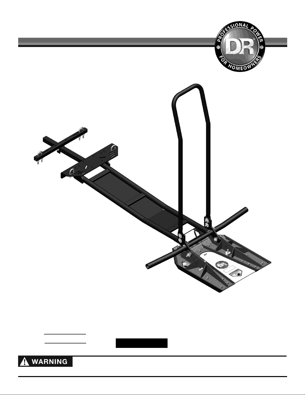
Read and understand this manual and all instructions before operating the DR® TreeChopper™.
`
Original Language
DR
®
TreeChopper™
SAFETY & OPERATING INSTRUCTIONS
DR Power Equipment
Toll-free phone: 1-800-DR-OWNER (376-9637)
Fax: 1-802-877-1213
Website: www.DRpower.com
Serial No.
Order No.
Page 2

This indicates a hazardous situation, which, if not avoided, could result in death or serious injury.
Table of Contents
This information is important in the proper use of your machine. Failure to follow this instruction could result in damage to
your machine or property.
This indicates a hazardous situation, which, if not avoided, could result in minor or moderate injury.
Chapter 1: General Safety Rules ....................................................................................................................................................................3
Chapter 2: Setting Up The DR® TreeChopper™ ..........................................................................................................................................8
Chapter 3: Operating the DR® TreeChopper™ ............................................................................................................................................16
Chapter 4: Maintaining The DR® TreeChopper™ .......................................................................................................................................18
Chapter 5: Troubleshooting ...........................................................................................................................................................................21
Chapter 6: Parts Lists and Schematic Diagrams .........................................................................................................................................22
Conventions used in this manual
Serial Number and Order Number
A Serial Number is used to identify your machine and is located on the Serial Number Label on your machine. An Order Number
is used to check and maintain your order history and is located on your packing slip. For your convenience and ready reference,
enter the Serial Number and Order Number in the space provided on the front cover of this manual.
Additional Information and Potential Changes
DR Power Equipment reserves the right to discontinue, change, and improve its products at any time without notice or obligation
to the purchaser. The descriptions and specifications contained in this manual were in effect at printing. Equipment described
within this manual may be optional. Some illustrations may not be applicable to your machine.
2 DR
®
TreeChopper™
Page 3

Read this safety & operating Instructions manual before you install or use the DR TreeChopper. Failure to read this manual could
result in personal injury or equipment damage. Become familiar with the operation and service recommendations to ensure the
best performance from your machine. If you have any questions or need assistance, please contact us at www.DRpower.com or
call toll-free 1-800-DR-OWNER (376-9637) and one of our Technical Support Representatives will be happy to help you.
Chapter 1: General Safety Rules
#31191
#13649
#31211
#31180
#31187
#31207
Labels
Your DR TreeChopper carries prominent labels as reminders for its proper and safe use. Shown below are copies of all the Safety
and Information labels that appear on the equipment. Take a moment to study them and make a note of their location on your
TreeChopper as you set up and before you operate the unit. Replace damaged or missing safety and information labels
immediately.
CONTACT US AT www.DRpower.com 3
Page 4

Operating this TreeChopper safely is necessary to prevent or minimize the risk of death or serious injury. Unsafe operation can
create a number of hazards for you as well as anyone else in the nearby area. Always take the following precautions when
operating this TreeChopper:
Keep in mind that the operator or user is responsible for accidents or hazards occurring to other people, their property, and
themselves.
Read the ATV operators manual, the Winch operators manual and all warning labels before operating.
Prior to use remove the blade guard and ensure that the blades are properly adjusted as outlined in your TreeChopper’s
operation manual.
Stay clear of all moving parts or joints that may be a potential pinch point hazard.
Never allow bystanders to stand, or ride on the chassis or the head assembly of the TreeChopper.
Always reinstall the blade guard after use and prior to transport.
Never operate the TreeChopper without the tree guard properly affixed and adjusted per the instructions outlined in your
operators manual.
Never attempt to cut trees larger than 4" in diameter.
Never operate the TreeChopper without the extension arms installed.
Never equip a TreeChopper to an ATV that is less than 400cc and always operate the ATV in four wheel drive.
Inspect all hardware, mounting brackets, blades and guards for loose, bent, broken or failing components prior to operation.
If any component is damaged, or missing, replace it immediately prior to operation.
Always follow all warnings outlined in your ATV’s operation manual and on the machines warning labels.
Never exceed 15 mph (24 kph) even with the TreeChopper in the raised transport position.
Keep bystanders at least 100 feet away from your intended work area and always be aware of their location.
Never attempt to cut a tree larger than 4" in diameter. The TreeChopper is designed to only cut trees. Do not attempt to cut
wooden fence posts, rebar, or any object other than a 4" diameter or smaller tree.
Always wear an approved motorcycle helmet that fits properly and is equipped with a face shield in conjunction with
protective goggles to protect your eyes and face from stray branches or debris.
Avoid wearing loose clothing or jewelry, which can catch on moving parts.
We recommend wearing gloves while using the TreeChopper. Be sure your gloves fit properly and do not have loose cuffs or
drawstrings.
Wear shoes with non-slip treads when using your TreeChopper. If you have safety shoes, we recommend wearing them.
Never work on or use the TreeChopper barefoot or while wearing open toed shoes/sandals (footwear).
Wear a long sleeve shirt or riding jacket and long pants while operating the TreeChopper.
Protective Gear
Tragic accidents can occur if the operator is not alert to the presence of children and pets. Children are often attracted to the
machine and the chopping activity.
Never
assume that children will remain where you last saw them. Always follow these
precautions:
Never operate the TreeChopper with children or pets present. Keep children and pets at least 100 feet from the working area
and ensure they are under the watchful care of a responsible adult.
Be alert and put the ATV in “Park”, set the parking brake, turn the ATV off, lower the TreeChopper and install the guard if
children or pets enter the work area.
Never allow children under the age of 16 to operate the TreeChopper.
Safety for Children and Pets
Protecting yourself and those around you
4 DR
®
TreeChopper™
Page 5

Protecting yourself and those around you (continued)
Never cut trees near power lines, gas lines, or any other obstacle that may pose a fire, explosion, or electrical hazard. Never
assume a tree will fall where you intend it to.
Always stop the ATV, place the transmission in park (when applicable) set the parking brake, replace the blade guard and
lower the TreeChopper to the ground prior to allowing another person or pet to approach.
Never allow passengers to ride on the ATV while the TreeChopper is installed on the machine, even if the ATV is designed to
safely transport passengers.
Prior to chopping trees inspect the area you will be intending to cut in for any debris or objects that may pose a hazard.
Inspect all trees prior to chopping them by following the practices outlined in the TreeChopper operation manual.
Never attempt to cut a tree without first surveying the tree for branches that may cause an impalement hazard. Remove all
branches that pose such hazards prior to cutting. Failure to do so can cause serious injury or even death.
Always inspect the tree(s) you are intending to cut for ingrown hazards such as rocks, metal rebar, or fencing. Never attempt
to cut a tree that has an ingrown object.
Do not operate the ATV on slopes greater than 10° with the TreeChopper installed.
Always begin cutting on small diameter trees that are in the early stages of growth to learn the characteristics and techniques
of the TreeChopper equipped to your atv
Never operate the atv with one hand while the TreeChopper is mounted
Always approach all ravines, pot holes and ditches at a slow speed and head on to prevent rollover. Avoid all obstacles and
never attempt to chop a tree that lies near or in a ravine, ditch or other hazardous terrain feature.
Do not operate your TreeChopper with material wedged in the blades. Safely remove any stuck or jammed material prior to
using your TreeChopper. Once material is removed, inspect your TreeChopper Blades for damage, alignment, and spacing.
Never stand or ride on the TreeChopper head or chassis – never allow passengers or bystanders to do so either.
Always reinstall the blade guard after use and prior to transport. The blade guard should only be removed prior to cutting
trees and should be promptly reinstalled after use.
Never operate the TreeChopper without first inspecting all hardware connections for bent bolts, missing hardware, or
loosened components. Tighten or replace before use with DR components.
Learn to properly operate your ATV prior to using your TreeChopper.
Prior to and after use, always check the condition of the cutting blades. Sharpen or replace any damaged blade per the
instructions found in your operators manual.
When readying to cut a tree make sure you are firmly seated on the ATV. Never attempt to cut a tree in a slightly raised or
standing position.
Your TreeChopper is a powerful tool, not a plaything. Exercise extreme caution at all times. The machine is designed to chop
small trees. Do not use it for any other purpose.
Always follow ATV warning and riding instructions in your ATV manual. Failure to read your ATV manual could result in
personal injury or equipment damage.
Do not attempt to cut Trees with trunks larger than a 4 inch diameter.
Prior to use, check the TreeChopper to be sure all bolts are tight and the blades are properly adjusted. Floating head bolts
should be snug, but loose enough to allow the head to float and follow the contours of the ground.
Approach trees to be cut from a safe distance, approximately 10 feet.
Approach tree at a safe speed and accelerate through the tree during cutting.
Know how to stop your ATV quickly; see your ATV owners Manual.
Never operate TreeChopper in slippery, wet, muddy, or icy conditions.
See manufacturer’s instructions for proper operation and installation of accessories. Only use accessories approved by DR
Power Equipment.
Never use the machine without ensuring that all guards and shields are in place.
Never, under any conditions, remove, bend, cut, fit, weld, or otherwise alter standard parts on the TreeChopper. This
includes all shields and guards. Modifications to your machine could cause personal injuries and property damage and will
void your warranty.
CONTACT US AT www.DRpower.com 5
Page 6

Protecting yourself and those around you (continued)
Allow only one person on the ATV to operate the TreeChopper at any time.
If the TreeChopper should start making an unusual noise or vibration, stop the ATV and put it in park, lower the TreeChopper
to the ground, turn the ATV ignition to the “Off” position, remove the key and set the emergency brake, then inspect for
damage. Vibration is generally a warning of trouble. Check for damaged parts and clean, repair, and/or replace as necessary.
Never tamper with safety devices. Check their proper operation regularly.
Before performing any maintenance or inspection procedure on the TreeChopper, stop the ATV and put it in park, lower the
TreeChopper to the ground, turn the ATV ignition to the “Off” position, remove the key and set the emergency brake.
Never allow people who are unfamiliar with these instructions to use the TreeChopper. Allow only responsible individuals
who are familiar with these rules of safe operation to use your machine.
Never overload or attempt to chop material beyond the manufacturer’s recommendation. Personal injury or damage to the
machine could result.
While using the TreeChopper, don't hurry or take things for granted. When in doubt about the equipment or your
surroundings, stop the machine and take the time to look things over.
Never operate the machine when under the influence of alcohol, drugs, or medication.
Use the machine only in daylight.
Stay alert for hidden hazards or traffic.
Keep all nuts and bolts tight and keep the equipment in good operating condition.
A Note to All Users
No list of warnings and cautions can be all-inclusive. If situations occur that are not covered by this manual, the operator must
apply common sense and operate this DR TreeChopper in a safe manner. Contact us at www.DRpower.com or call 1-800-DROWNER (376-9637) for assistance.
6 DR
®
TreeChopper™
Page 7

CONTACT US AT www.DRpower.com 7
Page 8
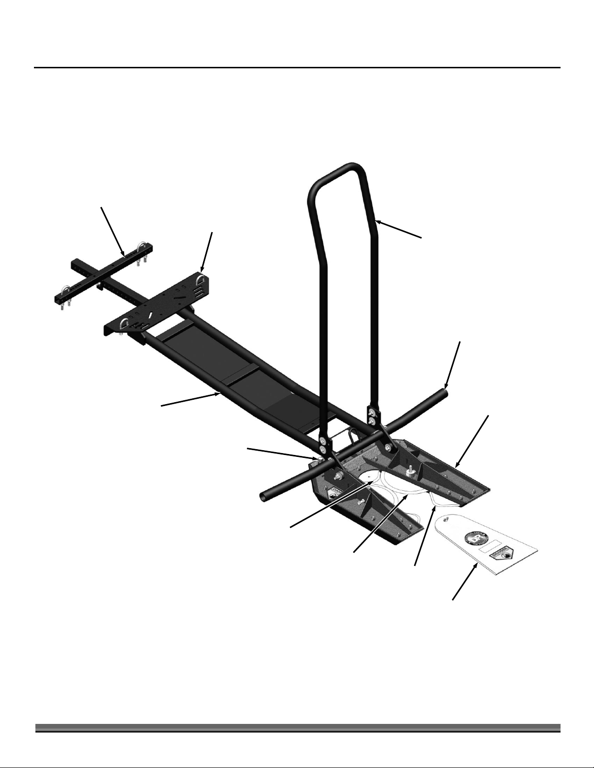
Figure 1
Tree Guard
Chassis
Extension
Arm
Cutting Head
Assembly
Universal
Mount
Universal
Cross Bar
Adjusting Bolt
Rear Blade
Circular
Front Blade
Front Blade
Blade Guard
Chapter 2: Setting Up The DR® TreeChopper™
It may be helpful to familiarize yourself with the controls and features of your DR TreeChopper as shown in Figure 1 before
beginning these procedures. If you have any questions at all, please feel free to contact us at www.DRpower.com.
DR TreeChopper Controls and Features
8 DR
®
TreeChopper™
Page 9
Specifications
Max Tree Size
4" Diameter
Frame
1-1/4" Diameter Pipe reinforced with a 14 Ga Steel Skid
Plate
Cutting Blades
3 Fixed Blades and 2 Rotating Cutting Blades
Weight
160 lbs
Dimensions
Head: 27" L X 22" W X 5" H
Chassis: 52" L X 43" W X 8" H
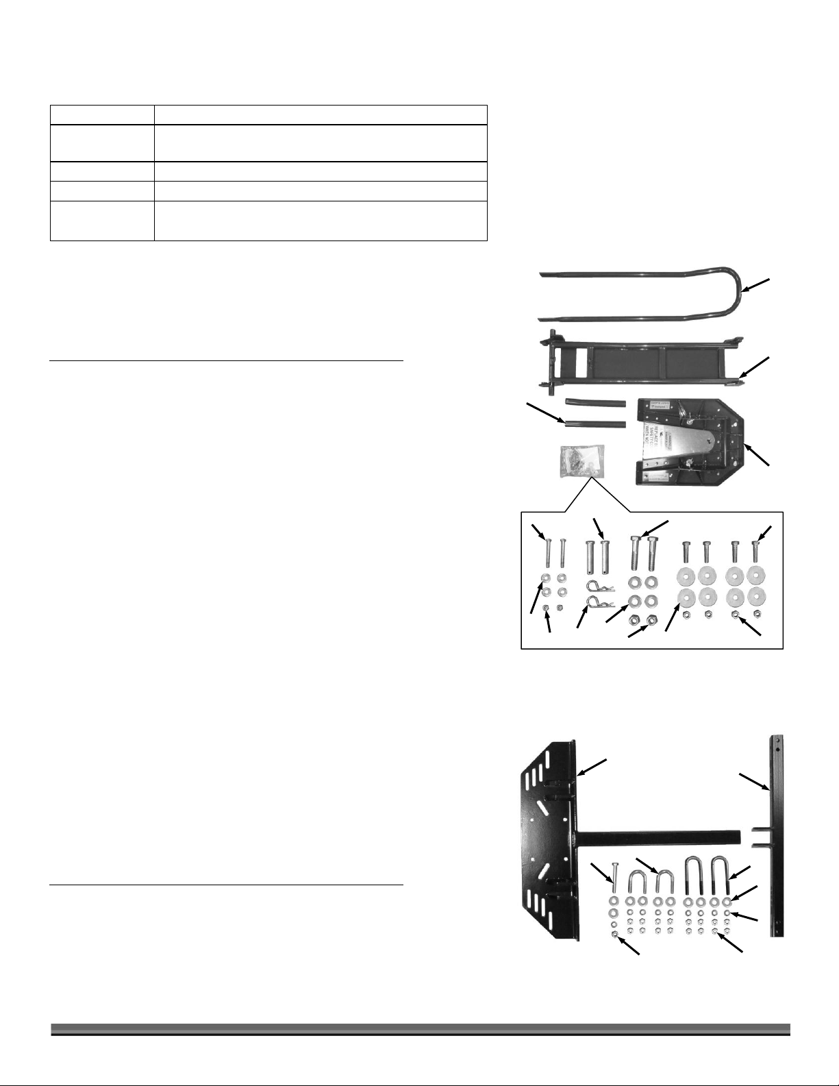
2
Figure 3
1
9
8
6
3
5
7
4
2
1
3
4
5
15
14 6 13
7
8
11
10 9 12
Figure 2
Common Parts Supplied: (Figure 2 and List below)
Note: These parts are supplied with every TreeChopper package. For assembly
reference, the item numbers below match the item numbers of the applicable
exploded illustration in Chapter 6.
Item Description Qty
01.............. Guard, Tree .................................................................1
02.............. Chassis .......................................................................1
03.............. Cutting Head Assembly .............................................1
04.............. Arm, Extension............................................................2
05.............. Bolt, 1/4-20 X 2.25", GR5, ZP....................................2
06.............. Pin, Pivot .....................................................................2
07.............. Bolt, 1/2-13 X 2.75", GR5, ZP....................................2
08.............. Bolt, HCS, 3/8-16 X 1-1/2", Gr5, ZP .........................4
09.............. Nut, Nylon Lock, 3/8-16, ZP......................................4
10.............. Washer, Fender, 3/8 X 1.5" OD ................................8
11.............. Nut, Nylon Lock, 1/2-13 ............................................2
12.............. Washer, Flat, 1/2", USS .............................................4
13.............. Pin, Hairpin Cotter, .12" Dia 2-3/8" .........................2
14.............. Nut, Nylon Lock, 1/4-20, ZP......................................2
15.............. Washer, Flat, 1/4", USS .............................................4
Compare the contents of the shipping package with the parts supplied list
above and Figure 2. If you have any questions, contact us at
www.DRpower.com or call 1-800-DR-OWNER (376-9637).
Kit Parts Supplied
The Kit that applies to your specific application has been determined by your
interaction with our customer service team. You should now have a Kit
reference number and the Kit name. Pick your Kit from the four Kits below to
continue comparing with the shipping package.
Round Tube Frame Kit #31956: (Figure 3 and List below)
Note: For assembly reference, the item numbers below match the item numbers of
the applicable exploded illustration in Chapter 6.
Item Description Qty
01.............. Cross Bar, Universal ...................................................1
02.............. Mount, Universal ........................................................1
03.............. Washer, Flat, 3/8", USS .............................................10
04.............. Nut, Nylon Lock, 3/8-16, ZP......................................1
05.............. Washer, Lock, 3/8" .....................................................9
Parts List Continued on next page
CONTACT US AT www.DRpower.com 9
Page 10

06.............. U-Bolt, 1.25" Id, 3/8-16 X 4" L...................................2
7
Figure 5
8
10 9 4
1
3
5 2 10
6
11 2 Figure 4
1 8 7
3
5
6
4
9
07.............. Nut, 3/8-16, Zp ...........................................................16
08.............. U-Bolt, 1.25" Id, 3/8-16 X 2.25" L .............................2
09.............. Bolt, 3/8-16 X 2.75", Gr5, ZP .....................................1
Compare the contents of the shipping package with the parts supplied list above and Figure 3. If you have any questions, contact
us at www.DRpower.com or call 1-800-DR-OWNER (376-9637).
Square Tube Frame Kit #31957: (Figure 4 and List below)
Note: For assembly reference, the item numbers below match the item numbers of
the applicable exploded illustration in Chapter 6.
Item Description Qty
01 ..............Cross Bar, Universal................................................... 1
02 ..............Mount, Universal........................................................ 1
03 ..............Washer, Flat, 3/8", USS ............................................. 10
04 ..............Nut, Nylon Lock, 3/8-16, ZP ..................................... 1
05 ..............Washer, Lock, 3/8" ..................................................... 9
06 ..............Nut, 3/8-16, Zp ........................................................... 16
07 ..............Bracket, Square Frame............................................... 4
08 ..............Bolt, HCS, 3/8-16 X 2-3/4", Gr5, ZP......................... 5
09 ..............Bolt, HCS, 3/8-16 X 3-3/4" ........................................ 4
Compare the contents of the shipping package with the parts supplied list above
and Figure 4. If you have any questions, contact us at www.DRpower.com or
call 1-800-DR-OWNER (376-9637).
Polaris Frame Kit #31958: (Figure 5 and List below)
Note: For assembly reference, the item numbers below match the item numbers of
the applicable exploded illustration in Chapter 6.
Item Description Qty
01 ..............Washer, Flat, 3/8", USS ............................................. 10
02 ..............Nut, Nylon Lock, 3/8-16, ZP ..................................... 1
03 ..............Washer, Lock, 3/8" ..................................................... 9
04 ..............U-Bolt, 1.25 ID, 3/8-16 X 4 L ..................................... 2
05 ..............Nut, 3/8-16, Zp ........................................................... 8
06 ..............Bracket, Square Frame............................................... 4
07 ..............Mount, Polaris ............................................................ 1
08 ..............Cross Bar, Polaris ....................................................... 1
09 ..............U-Bolt, 1.25 ID, 3/8-16 X 2.25 L ................................ 2
10 ..............Bolt, 3/8-16 X 2.75", Gr5, ZP..................................... 1
11 ..............Bolt, HCS, 3/8-16 X 3-3/4" ........................................ 4
Compare the contents of the shipping package with the parts supplied list above
and Figure 5. If you have any questions, contact us at www.DRpower.com or
call 1-800-DR-OWNER (376-9637).
10 DR
®
TreeChopper™
Page 11

Beam Frame Kit #31959: (Figure 6 and List below)
2
Figure 6
1 8 7
3 5 6 4 9
Bolt, Flat Washers
and Locknuts
Figure 7
Cutter
Assembly
Chassis
Note: For assembly reference, the item numbers below match the item numbers of
the applicable exploded illustration in Chapter 6.
Item Description Qty
01.............. Cross Bar, Universal ...................................................1
02.............. Mount, Universal ........................................................1
03.............. Washer, Flat, 3/8", USS .............................................6
04.............. Nut, Nylon Lock, 3/8-16, ZP......................................1
05.............. Washer, Lock, 3/8" .....................................................5
06.............. Nut, 3/8-16, Zp ...........................................................8
07.............. Bracket, Beam Frame .................................................2
08.............. Bolt, 3/8-16 X 2.75", Gr5, ZP .....................................1
09.............. Bolt, HCS, 3/8-16 X 4-1/2", Gr5, ZP .........................4
Compare the contents of the shipping package with the parts supplied list above
and Figure 6. If you have any questions, contact us at www.DRpower.com or
call 1-800-DR-OWNER (376-9637).
Installation Notes
The universal mounting plate has been designed to easily attach to most ATV frames.
The mounting bracket attaches to the frame of your ATV which must not be dented, bent, collapsed or rusted. Secure mounting
is necessary for safe and successful use of the TreeChopper.
The TreeChopper should only be installed on ATVs that are 400cc or more and have 4-wheel drive.
Always keep all guards and shields in place when the TreeChopper is not in use. This includes during assembly and while
attaching or detaching the TreeChopper to your ATV.
Proper installation of the mounting bracket onto the frame of your ATV is necessary for safe and successful use of the
TreeChopper. The mounting bracket must be securely affixed to the frame of the ATV. If mounting to the frame and skid plate,
the skid plate must be constructed of heavy metal. Do not attach to a plastic skid plate.
If the metal skid plate is not flat and causes the Mounting Bracket and Cross Brace to not be flat against the frame, you cannot
safely mount to your ATV. It is very important to make sure the mounting bracket fits securely to the frame of the ATV
Always install the Blade Guard when the TreeChopper is not in use.
Assembling and Installing the DR TreeChopper
Tools and supplies needed:
Two 7/16" Wrenches
Two 9/16" Wrenches
Two 3/4" Wrenches
Gloves
Mounting for ATVs
Note: The following photos in this chapter focus on the installation of the Round
Tube Frame Kit #31956 but the steps describe all kits. Please refer to the
Illustrations in Chapter 6 for accurate representation of the parts and
assembly order of your kit.
1. Attach the Cutting Assembly to the Chassis (Figure 7) with two 1/2-20
Bolts, four 1/2" Flat Washers and two 1/2-20 Locknuts using two 3/4"
Wrenches. Do not tighten the hardware completely to allow the Cutter
Assembly to rotate independently of the Chassis.
CONTACT US AT www.DRpower.com 11
Page 12

Never attempt to mount the Universal Mounting Bracket to your ATV by drilling into the frame, skid plates, or mounting bracket.
2. Temporarily attach the Universal Mount to the Chassis using the two Pivot
Pivot Pins
Figure 8
Chassis
Universal
Mount
Lifting
Rings
Figure 9
FWD
2.25"
U-Bolts
Figure 10
ATV Frame
U-Bolt Stop
Pins (Figure 8).
3. Slide the Universal Mount and Chassis under the ATV far enough so that the
non-removable lifting ring on the chassis is forward of the front of the winch
(or other lifting device) by one to two inches. This allows for a slight angle
during lifting (Figure 9). The Universal Mount should be centered as closely
as possible to the center of the ATV (side to side).
Note: Included in your hardware kit is a removable 2nd lifting ring and hardware if
you need to mount your TreeChopper farther forward. The two lifting rings locations
are available to allow for more flexibility when finding an accessible position to
attach the front mounting plate.
Note: Some plastic guarding or similar material may need to be removed to ensure
an ideal mounting point to the Frame.
4. Look under the ATV to determine the closest location on the Frame where
the Universal Bracket and Cross Bar can be attached. If you have a plastic
skid plate remove it from where the front and back mounting plates will
fasten to the frame. Make sure that the Universal mount is tight to the frame
or metal skid plate. If there is a plastic skid plate between the bracket and the
frame it should be removed so that the bracket tightens flat against the ATV
frame.
5. Unpin the Universal Mount from the Chassis and lift it into position against
the Frame to determine where the hardware can go around the Frame and
into the slots of the Mount.
12 DR
®
TreeChopper™
6. Round Tube Frame (also some Polaris Frames): Lower the Universal Mount
and place a 2.25 Long U-Bolt around the Frame on both sides where it can
rest against a stop on the rear facing side of the U-Bolt (Figure 10).
Square Tube Frame (also some Polaris Frames): Lower the Universal Mount
and place a Square Frame Bracket over the top of the Frame on both sides
where it (or the Bolts that will support it) can rest against a stop on the rear
facing side of the Bracket. Insert a 3/8-16 X 2-3/4" Bolt down through each hole
on the two brackets.
Beam Frame: Lower the Universal Mount and place a Beam Frame Bracket over
the Frame where it (or the Bolts that will support it) can rest against a stop on
the rear facing side of the Bracket. Insert a 3/8-16 X 4-1/2" Bolt down through
each hole on the bracket.
Note: “U-Bolt Stop, Square Bracket Stop, or Beam Bracket Stop” is an area of the
Frame where there is a cross piece or welding point that the U-Bolt , Square Frame
Bracket, or Beam Frame Bracket will push against as the TreeChopper cuts into a
tree. Never use a U-Bolt to mount the TreeChopper to a Square Tube Frame, or a
Square Frame Bracket and Bolts to mount the TreeChopper to a Round Tube
Frame.
Page 13

Universal
Mount
Figure 13
Universal
Cross Bar
U-Bolts, Flat
Washers and
Locknuts
Bolt, Flat Washers
and Locknut
7. Secure the Universal Mount to each U-bolt or Bolt with a Flat Washer, Lock
Universal
Mount
Figure 11
FWD
Flat Washers
and Locknuts
4" U-Bolts
Figure 12
U-Bolt
Stop
Washer and two Jam Nuts using a 9/16" Wrench for each Threaded portion
of the U-Bolts, or Bolts (Figure 11).
8. Position the Universal Cross Bar further back on the Frame than the
Universal Mount and place the tabs over the square tube of the Universal
Mount. Determine the best place to attach the Cross Bar to the Frame.
9. Round Tube Frame (also some Polaris Frames): When you have determined
the best place to attach the Cross Bar to the Frame, remove the Cross Bar
and place a 4" Long U-Bolt around the Frame on both sides to determine
where it can rest against a stopping point on the Frame (Figure 12).
Square Tube Frame (also some Polaris Frames): When you have determined
the best place to attach the Cross Bar to the Frame, remove the Cross Bar
and place a Square Frame Bracket over the top of the Frame on both sides
to determine where it (or the Bolts that will support it) can rest against a
stopping point on the Frame.
Beam Frame: When you have determined the best place to attach the Cross
Bar to the Frame, remove the Cross Bar and place a Beam Frame Bracket
over the top the Frame to determine where it (or the Bolts that will support
it) can rest against a stopping point on the Frame.
10. Reposition the Cross Bar against the Frame with the center Tabs over the
Universal Mount Tube (Figure 13). Insert the U-Bolts, or Bolts into the
holes in the Cross Bar. Install a Flat Washer, Lock Washer and two Jam
Nuts on each U-Bolt or Bolt using a 9/16" Wrench but leave the hardware
fairly loose for now.
11. Align the holes in the Tabs of the Cross Bar to the nearest holes in the
Universal Mount Tube that will allow the Cross Bar to rest tight against the
Frame. Install the 3/8-16 X 2-3/4" Bolt with a Flat Washer through the Tab
holes and Mount Tube. Install a Flat Washer and Locknut on the end of the
Bolt but only screw on by Hand.
CONTACT US AT www.DRpower.com 13
Page 14

Note: The Cross Bar can be angled front to back as needed to align with the hole in
Extension Arms
Figure 15
Bolt,
Flat Washers
and Locknut
Arm Bend
Facing Back
Chassis
Figure 14
Pivot Pins
Hairpin
Tree Guard
Figure 16
Bolt, Large Flat
Washers and Locknut
Lifting Device
The U-Bolt or Bolt Hardware must be tight to ensure that there is a strong
connection between the Mounts and Frame, but do not over-tighten. Overtightening could cause damage to your ATV frame and could weaken the
Hardware attaching the TreeChopper Frame to your ATV.
the Universal Mount as long as it rests flat against the ATV Frame Tube.
12. Tighten the U-Bolt or Bolt Hardware with a 9/16" Wrench(es).
13. Tighten the Bolt and Locknut going through the Cross Bar tabs with two
9/16" Wrenches.
14. Install the Tree Cutter Chassis to the Universal Mount with the two Pivot
Pins (head facing out) and Hairpins (pushed all the way on as shown)
(Figure 14).
15. Attach the extension arms to the Chassis with a 1/4-20 X 2-1/4" Bolt, two
1/4" Washers and a 1/4-20 Locknut for each arm (Figure 15). Tighten with
two 7/16" Wrenches.
16. Attach the Tree Guard to Chassis with four 3/8-16 X 1-1/2" bolts, eight
Fender Washers (one on the Bolt side and one on the Locknut side) and four
3/8-16 Locknuts using two 9/16" Wrenches (Figure 16).
14 DR
®
TreeChopper™
Page 15

Adjusting the Cutter Assembly Angle
Figure 17
Front
Touching
Flat Surface
1"
Jam Nut
Adjusting Bolt
Important!
Make sure the cutting assembly is properly adjusted using the two Adjuster
Bolts on the back of the Cutting Head Assembly as described below. This
adjustment should be made on a flat, hard surface such as concrete. The wheels
of the ATV must be on the same flat surface that you are adjusting the Cutter
Assembly angle to. These Bolts should be adjusted so that the front forks of the
Cutting Head Assembly are slightly pitched down. This enables the Cutting
Head Assembly to stay parallel to the ground when accelerating the ATV
through the tree.
1. Lower the Cutting Head Assembly with your lifting device until the forward
end of the Head just touches the concrete (Figure 17).
2. Measure from the back end of the Cutting Head Assembly to the concrete.
It should be 1" off the concrete.
3. If the back end of the Cutting Head Assembly is not 1" from the concrete,
loosen the adjuster Nut and turn the adjuster Bolts in or out equally until the
back end of the Cutting Head Assembly is 1" from the concrete when the
front end is just touching.
4. Tighten the Jam Nut when adjustment is complete.
Removal and Installation of the Cutter Assembly
The TreeChopper can be quickly and easily installed or removed from the Universal Mount. To remove the TreeChopper simply
remove the Hairpin Cotter Pins and Pivot Pins to drop the Chassis down onto the ground (Figure 14 on page 14). The Head
Assembly and Chassis can now be pulled away from the ATV. Install in the reverse order.
CONTACT US AT www.DRpower.com 15
Page 16

To avoid injury to yourself as well as others, you must read, understand and follow the warnings listed in “Chapter 1 General
Safety Rules” before operating an ATV equipped with your TreeChopper.
Chapter 3: Operating the DR® TreeChopper™
Blade Guard
Figure 18
Thumbscrew
Lifting Device
It may be helpful to better familiarize yourself with the features of your TreeChopper by reviewing Figure 1 in Chapter 2 before
beginning the steps outlined in this chapter.
Before You Begin
The TreeChopper can safely cut trees up to four inches in diameter and very close to ground level which is necessary to lessen
the possibility of re-growth.
Before operating check the area where the TreeChopper will be used. If rocks or other debris will hinder access to the tree to be
cut check for other angles of approach or move the rocks and debris. Keep people, livestock and pets out of the cutting area.
Always start out cutting small trees, less than 2" in diameter to familiarize yourself with the necessary actions, speed and
techniques to cutting trees with the TreeChopper. Once you have become comfortable with cutting smaller trees, you can move
on to larger trees.
Learn how to properly operate your ATV prior to using the TreeChopper.
Do not attempt to cut Trees with trunks larger than a 4 inch diameter.
Always make sure your ATV is in Four Wheel Drive and in Low Gear prior to cutting a Tree.
Operation
1. The TreeChopper can be raised and lowered by attaching a lifting device
(winch, ratchet strap, chain) and using one of the hooks on the chassis
(Figure 18). This allows for quicker travel to and from the cutting areas while
the TreeChopper is in the raised position. Remember, the TreeChopper must
be on the ground and properly adjusted prior to cutting.
2. Before beginning to cut, turn off your ATV and set the TreeChopper on the
ground, making sure the winch line or other lifting device is loose. The
TreeChopper will float along the terrain. This allows for the TreeChopper to
cut close to the ground.
3. Remove the blade guard and visually inspect the unit. Make sure bolts are
tight and the circular blades are not obstructed.
4. When first learning how to operate the TreeChopper and becoming
comfortable with its use, select small trees 2 inches in diameter or less. It is
important to get experience and establish a comfort level by cutting smaller
trees first.
5. Always make sure that the TreeChopper is lined up so that the trunk of the
tree is center to the cutting blades. To be sure the TreeChopper is centered,
slowly drive into the tree to "bump" it to check that the tree can clear the
front blades (indicating that the tree is less than 4" in diameter) and that the
tree is against the rotating Circular Blades. Once the tree trunk is centered
and you have cleared the area of debris you are ready to cut.
Note: If the tree is unable to pass by the Front Blades, the tree may be larger than
4" in diameter at the trunk. This is an indication that you will not be able to cut the
tree, or that there is a hidden obstacle, such as a rock, stump, or other object that
16 DR
®
TreeChopper™
Page 17

would impede the cut. If there are no hidden obstacles impeding the cut, you may be able to approach the tree from a different
angle to "bump" it and find that the trunk in that area is less than 4" in diameter.
6. Back your ATV away from the tree to approximately 8 to 10 feet. Accelerate the ATV in a forward motion through the tree.
Impact should be minimal. Once you have gained confidence and experience with tree trunks 2 inches in diameter and less
you should be ready to cut bigger trees with trunks of up to 4 inches. You will also find that you are able to cut trees at a
steady pace as you become comfortable identifying chop-able trees while in motion.
Note: After cutting, wash the TreeChopper with low pressure water spray. After washing, spray lubricating oil or silicone on the blades to
prevent rusting.
CONTACT US AT www.DRpower.com 17
Page 18

Chapter 4: Maintaining The DR® TreeChopper™
PROCEDURE
BEFORE
EACH USE
AFTER FIRST
20 TREES
AFTER EACH
USE
Check General Equipment Condition
Check if Cutting Blades are dull or damaged (if damaged replace immediately)
Remove debris wrapped around Cutter Blades.
Check and adjust Cutting Blades
Lubricate Cutting Blades
Before performing any maintenance procedure or inspection, stop the ATV and put it in park, lower the TreeChopper to the
ground, turn the ATV ignition to the “Off” position, remove the key and set the emergency brake.
Never use a grinding wheel to sharpen the Blades. The heat produced from grinding will affect the Blade strength causing it
to break during use creating a hazard for the ATV and the driver.
Wear gloves to protect your hands from sharp blade edges.
Wear safety glasses to protect your eyes from flying metal shavings.
Regular maintenance is the way to ensure the best performance and long life of your machine. Please refer to this manual for
maintenance procedures.
Regular Maintenance Checklist
Protecting the Cutting Blades
Supplies Needed:
Silicone Spray Lubricant
1. After use, clean the Blades of any debris and coat with silicone spray lubricant on all Blade surfaces to prevent rusting.
Note: Always have the Blade Guard installed over the Blades when the TreeChopper is not in use.
Sharpening the Cutting Blades
Tools and Supplies needed:
Flat File
Leather Gloves
Safety Glasses
1. File the cutting edges of the Blades.
Note: Do not sharpen to a razor sharp edge.
18 DR
®
TreeChopper™
Page 19

Replacing the Cutting Blades
Bolts, Flat Washers
and Locknuts
Figure 19
Coupling Nuts
and Adjustment
Pin Bushings
Figure 20
Locknuts
Front
Circular
Blades
Figure 21
Front Triangular
Blades
Rear
Blade
Rear
Shim
Front
Shim
Circular
Blade
Bushings
Wear gloves to protect your hands from sharp blade edges.
Tools and Supplies needed:
Two 3/4" Wrenches
9/16" Wrench
Leather Gloves
1. Place the Cutter Head Assembly flat on the ground and remove the Bolt, Flat
Washers and Locknut from the two pivot points using two 3/4" Wrenches
(Figure 19).
2. Remove the two Coupling Nuts that secure the Front Circular Blades with a
3/4" Wrench (Figure 20).
3. Remove the two Adjustment Pin Bushings that were under the Coupling
Nuts.
4. Remove the 18 Locknuts that secure the Upper Cutting Plate to the Lower
Cutting Plate using a 9/16" Wrench.
5. Pull the Upper Cutting Plate away from the Lower Cutting Plate.
Note: Take note of all Shim and Spacer locations for reassembling.
6. Remove the front and rear Shims (Figure 21).
Note: The front Triangular Blades can be flipped so the unused rear facing sharper
edge is now facing forward to minimize sharpening time. However when
both edges are dull the entire cutting edge will need sharpening.
7. Remove and replace the Blades as needed.
Note: Ensure that the Circular Blade Bushings are in place when the Blades are
installed.
8. Reassemble the Cutter Head Assembly in the reverse order that it was
disassembled.
9. Perform a Circular Blade adjustment before tightening Coupling Nuts and
18 Locknuts mentioned in steps 2 and 4 (see next section “Front Circular
Blade Adjustment”).
CONTACT US AT www.DRpower.com 19
Page 20

Front Circular Blade Adjustment
Figure 22
Coupling
Nut
Adjustment
Pin Bushing
Jam Nuts
Bolt
Even Space
Gap
Wear gloves to protect your hands from sharp blade edges.
Tools and Supplies needed:
1/2" Breaker Bar and 3/4" Socket
9/16" Wrench
Leather Gloves
1. Loosen the Coupling Nuts at the center of each circular Blade with a 1/2"
Breaker Bar and 3/4" Socket (Figure 22).
Note: Keep the spaces between the circular Blades and rear Blade the same on both
sides of rear Blade when adjusting in next step.
2. Loosen the Jam Nuts and adjust the Bolts with two 9/16" Wrenches so the
two Circular Blades are close enough together that a piece of paper can be
dragged through with some resistance but without ripping or being cut.
3. When adjustment is accurate, firmly tighten the two Coupling Nuts using a
1/2" Breaker Bar and 3/4" Socket.
4. Tighten the Jam Nuts against the Frame to hold the end of the Bolt against
the Adjustment Pin Bushings.
Note: The two Circular Blades must rotate. Make sure that the Blades are not
obstructed and are rotating on the Bushings.
20 DR
®
TreeChopper™
Page 21

Chapter 5: Troubleshooting
SYMPTOM
POSSIBLE CAUSE
Cutter Head Assembly is
off center
Attaching hardware from mount to frame is loose; tighten hardware.
A pivot pin has pulled out of chassis and mount; reattach pin.
Trees becoming harder
to cut
Blades need sharpening; sharpen blades.
Blades are damaged; replace blades as needed.
Blades are out of adjustment; adjust blades.
Circular Blades are not spinning freely; clean the top and underside of the Blades. Never
loosen hardware in an attempt to allow the blades to rotate.
Trees are not being cut
as close to the ground
Cutter head assembly pivot needs adjustment; readjust bolts and jam nuts as required.
Before performing any maintenance procedure or inspection, stop the ATV and put it in park, lower the TreeChopper to the
ground, turn the ATV ignition to the “Off” position, remove the key and set the emergency brake.
Most problems are easy to fix. Consult the Troubleshooting Table below for common problems and their solutions. If you
continue to experience problems, contact us at www.DRpower.com or call toll-free 1-800-DR-OWNER (376-9637) for support.
Troubleshooting Table
CONTACT US AT www.DRpower.com 21
Page 22

Chapter 6: Parts Lists and Schematic Diagrams
Parts List – FRAME ASSEMBLY
NOTE: Part numbers listed are available through DR Power Equipment.
Ref# Part# Description
Ref# Part# Description
1 311571 Cutting Head
2 311791 Chassis, Asm W/ Labels
3 311601 Chassis
4 180811 Washer, Lock, 3/8
5 112391 Washer, Flat, 3/8, Uss
6 126831 Nut, 3/8-16, Zp
7 311761 Ubolt, 1.375 Id, 3/8-16 X 3-7/16 L
8 311801 Label, Chassis
9 311681 Guard, Tree
10 311461 Arm, Extension
11 114631 Bolt, 1/4-20 X 2.25, Gr5 Zp
12 110731 Nut, Nylon Lock, 1/4-20, Zp
13 112381 Washer, Flat, 1/4" Uss
14 101791 Washer, Flat, 1/2-13
15 311721 Bolt, 1/2-13 X 2.75, Gr5 Zp
16 110721 Nut, Nylon Lock, 1/2-13
17 119851 Bolt, Hcs, 3/8-16 X 1.5
18 110751 Nut, Nylon Lock, 3/8-16, Zp
19 311731 Pin, Hairpin Cotter, .12 Dia 2-3/8
20 311631 Pin, Pivot
21 311911 Label, 15 Mph Max
22 312071 Label, Tree Guard, Left
23 311871 Label, Tree Guard, Right
24 312091 Washer, Fender, 3/8 X 1.5" Od
22 DR
®
TreeChopper™
Page 23

Schematic – FRAME ASSEMBLY
CONTACT US AT www.DRpower.com 23
Page 24

Parts List – HEAD ASSEMBLY
NOTE: Part numbers listed are available through DR Power Equipment.
Ref# Part# Description
Ref# Part# Description
1 311471 Plate, Lower Cutting
2 311481 Plate, Upper Cutting
3 311491 Blade, Front
4 311501 Shim, Front
5 311511 Blade, Circular
6 311521 Bushing, Circular Blade
7 311531 Blade, Rear
8 311541 Shim, Rear
9 311551 Bushing, Adjustment Pin
10 311561 Shim, Cutting Plate
11 311611 Guard, Blade
12 311961 Bolt, Carriage, 3/8-16 X 1.25
13 311981 Nut, Wing, 1/4-20, Zp
14 119851 Bolt, Hcs, 3/8-16 X 1.5
15 126831 Nut, 3/8-16, Zp
16 229091 Bolt, Hhcs, 1/2-13 X 1.5, Gr5 Zp
17 229101 Nut, Hex, 1/2-13, Gr5 Zp
18 110751 Nut, Nylon Lock, 3/8-16, Zp
19 311451 Nut, 1/2-13, Coupling
20 311591 Bolt, Carriage, 1/2-13 X 2.5
21 311581 Bolt, Carriage, 3/8-16 X 1.25
22 311991 20ga Shim, Cutting Plate
23 312111 Label, Warning, Blade Guard
24 136491 Label, Danger
25 192021 Label, Dr Logo, 4.0", 4 Color
24 DR
®
TreeChopper™
Page 25

Schematic – HEAD ASSEMBLY
CONTACT US AT www.DRpower.com 25
Page 26

Parts List and Schematic – Round Tube Frame Kit #31956
NOTE: Part numbers listed are available through DR Power Equipment.
Ref# Part# Description
Ref# Part# Description
1 311661 Cross Bar, Universal
2 311641 Mount, Universal
3 112391 Washer, Flat, 3/8, USS
4 110751 Nut, Nylon Lock, 3/8-16, ZP
5 180811 Washer, Lock, 3/8"
6 311751 U-Bolt, 1.25 ID, 3/8-16 X 4" L
7 126831 Nut, 3/8-16, ZP
8 311741 U-Bolt, 1.25 ID, 3/8-16 X 2.25" L
9 123371 Bolt, 3/8-16 X 2-3/4, Gr5 ZP
26 DR
®
TreeChopper™
Page 27

Parts List and Schematic – Square Tube Frame Kit #31957
NOTE: Part numbers listed are available through DR Power Equipment.
Ref# Part# Description
1 311661 Cross Bar, Universal
2 311641 Mount, Universal
3 112391 Washer, Flat, 3/8", USS
4 110751 Nut, Nylon Lock, 3/8-16, ZP
5 180811 Washer, Lock, 3/8"
6 126831 Nut, 3/8-16, ZP
7 311881 Bracket, Square Frame
8 123371 Bolt, 3/8-16 X 2-3/4", Gr5, ZP
9 150701 Bolt, HCS, 3/8-16 X 3-3/4"
CONTACT US AT www.DRpower.com 27
Page 28

Parts List and Schematic – Polaris Frame Kit #31958
NOTE: Part numbers listed are available through DR Power Equipment.
Ref# Part# Description
1 112391 Washer, Flat, 3/8, USS
2 110751 Nut, Nylon Lock, 3/8-16, ZP
3 180811 Washer, Lock, 3/8"
4 311751 U-Bolt, 1-1/4 ID, 3/8-16 X 4" L
5 126831 Nut, 3/8-16, ZP
6 311881 Bracket, Square Frame
7 311921 Mount, Polaris
8 312041 Cross Bar, Polaris
9 311741 U-Bolt, 1.25 ID, 3/8-16 X 2-1/4" L
10 123371 Bolt, 3/8-16 X 2-3/4, Gr5, ZP
11 150701 Bolt, HCS, 3/8-16 X 3-3/4"
28 DR
®
TreeChopper™
Page 29

Parts List and Schematic – Beam Frame Kit #31959
NOTE: Part numbers listed are available through DR Power Equipment.
Ref# Part# Description
1 311661 Cross Bar, Universal
2 311641 Mount, Universal
3 112391 Washer, Flat, 3/8", USS
4 110751 Nut, Nylon Lock, 3/8-16, ZP
5 180811 Washer, Lock, 3/8"
6 126831 Nut, 3/8-16, ZP
7 311671 Bracket, Beam Frame
8 123371 Bolt, 3/8-16 X 2-3/4", Gr5, ZP
9 229121 Bolt, HHCS, 3/8-16 X 4-1/2", Gr5, ZP
CONTACT US AT www.DRpower.com 29
Page 30

Notes:
30 DR
®
TreeChopper™
Page 31

Notes:
CONTACT US AT www.DRpower.com 31
Page 32

Daily Checklist for the DR® TreeChopper™
Before performing any maintenance procedure or inspection, stop the ATV and put it in park, lower the TreeChopper to the
ground, turn the ATV ignition to the “Off” position, remove the key and set the emergency brake.
Before performing any maintenance procedure or inspection, stop the ATV and put it in park, lower the TreeChopper to the
ground, turn the ATV ignition to the “Off” position, remove the key and set the emergency brake.
To help maintain your DR TreeChopper for optimum performance, we recommend you follow this checklist each time you use
your TreeChopper.
[ ] Check that the cutting blades are clear of debris, making sure to avoid hand or foot contact with the blades.
[ ] Check that Circular Blades turn freely.
[ ] Check that Blades are lubricated after use to prevent corrosion.
End of Season and Storage
Wash the TreeChopper with low pressure water spray. After washing, lightly spray lubricating oil on the blades to prevent
rusting.
The TreeChopper should be stored in a dry and safe place with blade guard installed.
Be sure all nuts, bolts, and screws are securely fastened.
7 5 M E I G S R O A D , P . O . B O X 2 5 , V E R G E N N E S , V E R M O N T 0 5 4 9 1
©2012 Country Home Products, Inc. All rights reserved 311431
 Loading...