

Page 1

CHIPPER/SHREDDER
Operating & Assembly Instruction Manual
Model: Tractor Attachment Chipper/Shredder TPH-184CHP
This manual contains information concerning proper and improper operating procedures,
warnings, maintenance, troubleshooting, assembly, and tips. Everyone who operates this
machine should read these instructions and be thoroughly familiar with them.
P/N 911-0287
10/23/06
Page 2
SECTION I – SAFETY
This symbol points out important safety instructions, which if not followed,
could endanger the personal safety and/or property of yourself and others. Read and
follow all instructions in this manual before attempting to operate your shredder/chipper.
Failure to comply with these instructions may result in personal injury. When you see
this symbol - heed its warning.
THIS MACHINE IS CAPABLE OF INFLICTING SERIOUS INJURY
IF
OPERATED IMPROPERLY -- READ WARNINGS & CAUTION LABELS.
INTENDED USE
Never use your shredder/chipper for any other purpose than shredding and chipping limbs
or other lawn and garden debris. It is designed for this use and any other use many cause
serious injury.
DANGER: Rotating cutting blade.
Keep hands and feet out of inlet and discharge opening while machine is running.
DANGER: This machine can CRUSH, GRIND, CUT, and SEVER parts of your body if they
enter the inlet or discharge area of your shredder/chipper.
DANGER: Your shredder/chipper was built to be operated according to the rules for safe
operation in this manual. As with any type of power equipment, carelessness or error on
the part of the operator can result in serious injury. If you violate any of these rules, you
may cause serious injury to yourself or others.
2
Page 3
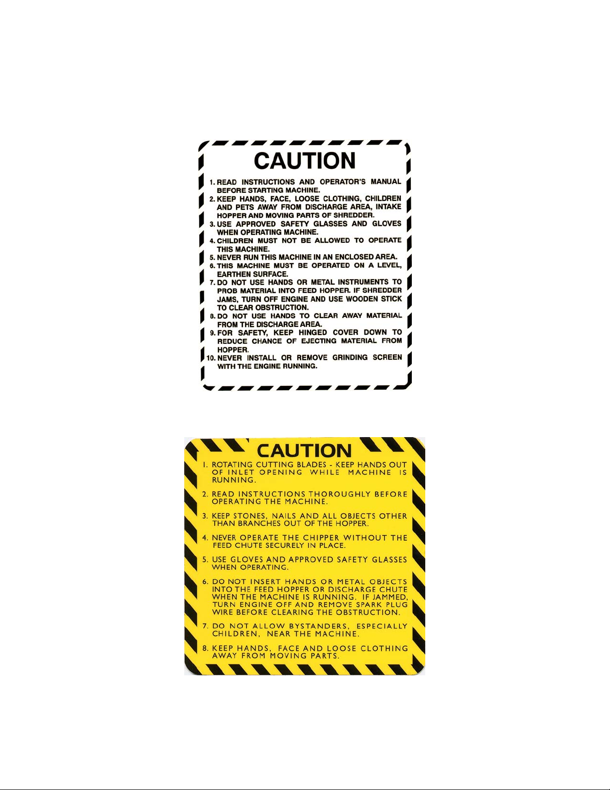
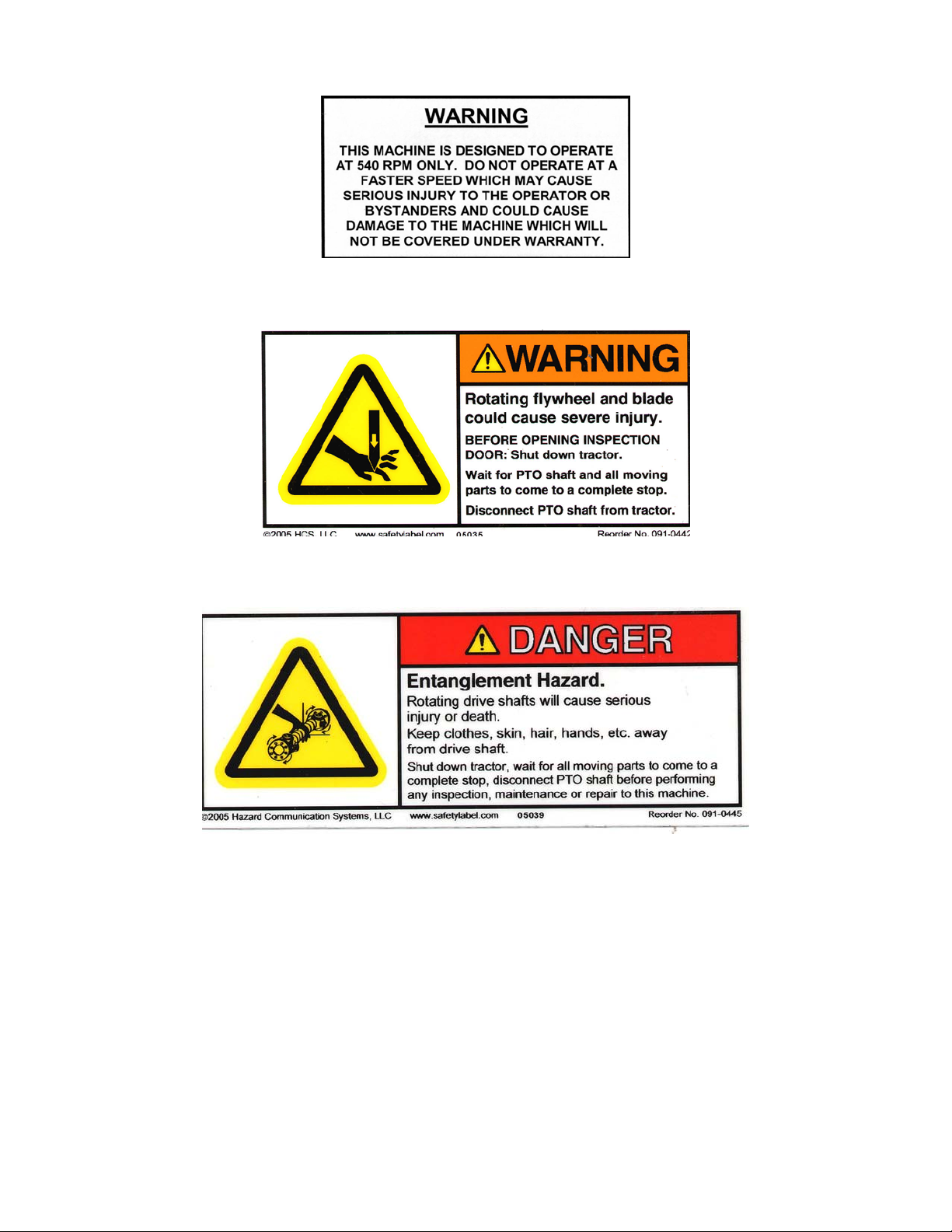
MAKE CERTAIN THAT ALL SAFETY LABELS ON THIS EQUIPMENT ARE KEPT
CLEAN AND IN GOOD CONDITION. IF YOU NEED REPLACEMENT LABELS,
ORDER BY PART NUMBER.
080-0962
080-0967
3
Page 4
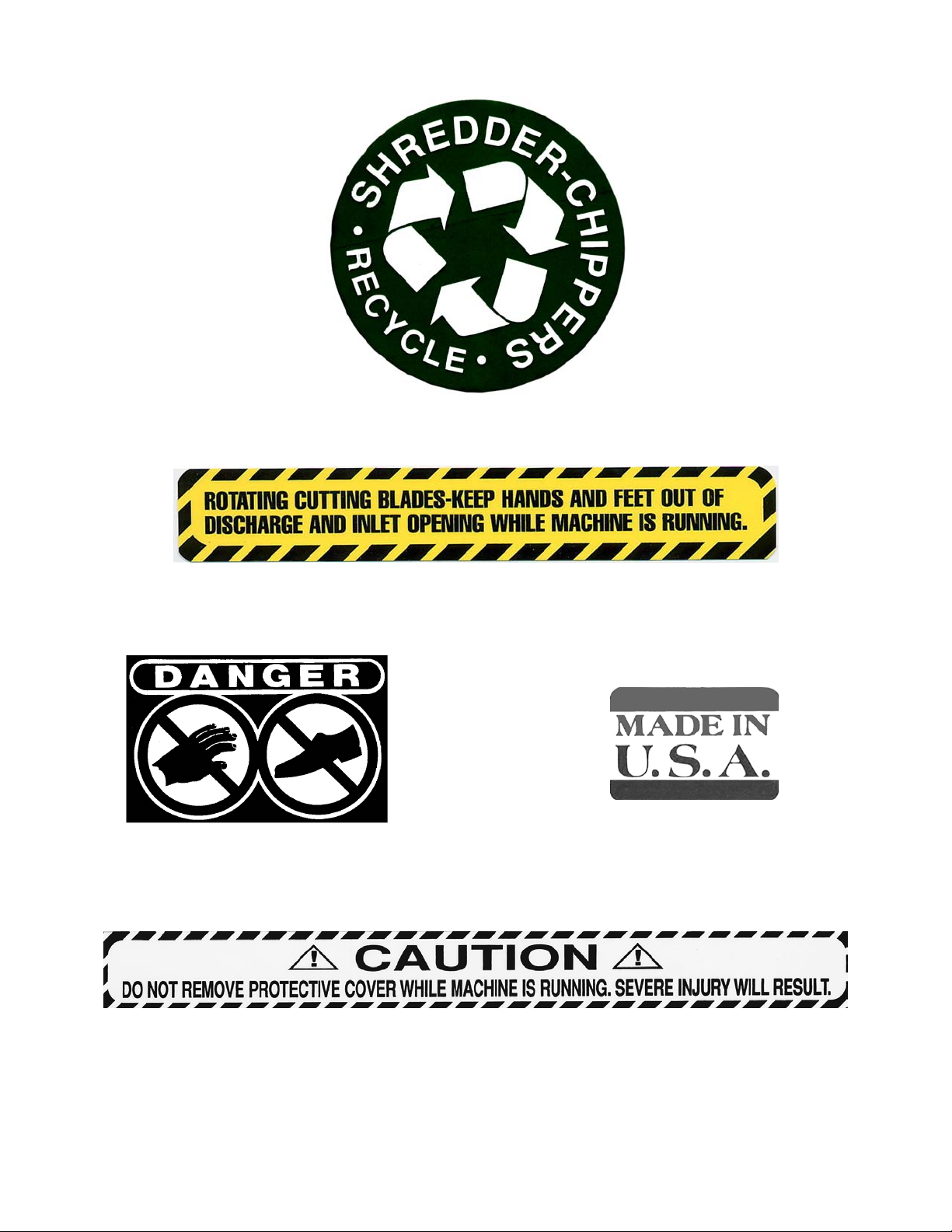
091-0057
091-0044
091-0055
091-0062
091-0059
4
Page 5
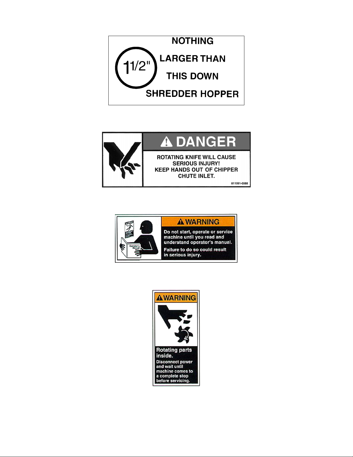
091-0064
091-0088
091-0380
091-0381
5
Page 6
091-0385
091-0442
091-0445
6
Page 7

SAFE OPERATION PRACTICES
TRAINING
• Read this owner’s manual carefully in its entirety before attempting to assemble this machine. Read, understand,
and follow all instructions on the machine before operation. Be completely familiar with the controls and the
proper use of the machine before operating it. Keep this manual in a safe place for future and regular reference
and for ordering replacement parts.
• Know how to stop the unit and disengage the controls quickly.
• Never allow children to operate the unit. Never allow adults to operate the equipment without proper instruction.
Only responsible individuals who are familiar with these rules of safe operation should be allowed to use your unit.
• Keep the area of operation clear of all persons, particularly small children and pets. Stop the engine when they
are in the vicinity of the unit. Keep work area clean and clear of branches or obstacles, which could cause you to
stumble or fall.
• Keep in mind that the operator or user is responsible for accidents or hazards occurring to other people, their
property, and themselves.
• Your shredder/chipper is a powerful tool, not a plaything. Exercise extreme caution at all times. Your unit has
been designed to shred and chip. Do not use it for any other purpose.
• If situations occur which are not covered in this manual, use care and good judgment. Contact your place of
purchase for additional assistance.
PREPARATION
• Thoroughly inspect the area where the equipment is to be used and remove all foreign objects.
• Do not operate the machine without wearing adequate outer garments and safety goggles. Always wear safety
glasses or goggles during operation and while performing any adjustment or repair, to protect eyes from foreign
objects that may be thrown from the machine. Be sure your glasses or goggles fit properly.
• Avoid loose-fitting clothes and use protective footwear that will improve footing on slippery surfaces. Shirt and
slacks that cover the arms and legs and steel-toed shoes are recommended. Secure hair above shoulders. Do
not wear loose clothes or jewelry that can be caught in moving parts. Never operate a unit in bare feet, sandals or
sneakers. Wear gloves when feeding material into the shredder hopper or chipper chute. Be sure your gloves fit
properly and do not have loose cuffs or drawstring.
• Never attempt to make any adjustments without shutting off the tractor and disengaging the P.T.O. drive shaft.
OPERATION
• Never place your hands, feet, or any part of your body in the shredder hopper, chipper chute, discharge opening,
or near or under any moving part while the shredder/chipper is running. Keep clear of the discharge opening at all
times. If it becomes necessary to push material into the shredder hopper or chipper chute, use a small diameter
stick, NOT YOUR HANDS.
• Keep your face and body back from the shredder hopper and chipper chute to avoid accidental bounce back of
any material.
• The shredder/chipper is designed to be run with the weight of the unit on the ground. Shredding or chipping with
the unit while it is off the ground can result in injury to yourself or others, or damage to the machine which may not
be covered under warranty.
• The machine should only be operated on a level surface. Never operate your unit on a slippery, wet, muddy, or
icy surface.
• Exercise caution to avoid slipping or falling.
• Stay alert for hidden hazards or traffic. Do not carry passengers.
• If the cutting mechanism strikes a foreign object or if your machine should start making an unusual noise or
vibration, immediately stop the tractor and wait for all moving parts to come to a complete stop. After the machine
has come to a complete stop proceed as follows:
• Inspect for any damage.
7
Page 8

• Repair or replace any damaged parts before restarting and operating the machine.
• If the machine should start to vibrate abnormally, immediately stop the tractor and wait for all moving parts to come
to a complete stop and inspect for the cause. Vibration is generally a warning sign of trouble.
• Disengage the P.T.O. drive shaft when leaving the operating position.
• Disengage the P.T.O. when moving the shredder/chipper.
• Stop the tractor and disconnect the P.T.O. drive shaft when making any repairs, adjustments and inspections.
• Take all possible precautions as recommended by the manufacturer when leaving the machine unattended. Stop
the tractor and remove the key if so equipped.
• Before cleaning, repairing, or inspecting, shut off the tractor and make certain the flywheel and all moving parts
have come to a complete stop.
• Never run this machine in an enclosed area as the exhaust from the tractor engine contains carbon monoxide,
which is an odorless, tasteless, and deadly poisonous gas.
• Keep all guards and safety devices in place and operating properly. Do not operate the machine if all safety
guards are not in place.
• Do not use the unit with the shredder hopper or chipper hopper removed.
• Keep children and pets away.
• Tragic accidents can occur if the operator is not alert to the presence of small children.
• Keep children out of the work area and under the watchful eye of a responsible adult other
than the operator.
• Be alert and turn the unit off if a child enters the area.
• Never allow children to operate the shredder/chipper.
• Do not overload or attempt to shred or chip material beyond manufacturers recommendation. Personal injury or
damage to the machine could result.
• Never operate the machine at high transport speeds or on hard or slippery surfaces.
• Never allow bystanders near the unit while running.
• Only use accessories approved for this machine by the manufacturer. Read, understand, and follow all the
instructions provided with the approved accessory.
• Only operate unit in good daylight. Do not operate unit at night or in dark areas where your vision may be
impaired.
• Use extreme caution when reversing or pulling the machine towards you.
• This machine is designed to operate at 540 RPM only. Do not operate at a faster speed which may cause serious
injury to the operator or bystanders and could cause damage to the machine which will not be covered under
warranty.
• Never pick up or transport the machine while the P.T.O. drive shaft is engaged.
• Do not operate while under the use of alcohol, drugs, or medication. A clear mind is essential for safety.
• Do not allow anyone who is not alert to operate this machine.
• When feeding material into this equipment, be extremely careful that pieces of metal, rocks, or other foreign
objects are not included. Personal injury or damage to the machine could result.
• Keep area of discharge clear of people, animals, buildings, glass or anything else that will obstruct clear
discharge, cause injury or damage. Wind can also change discharge direction, so be aware.
• Do not allow an accumulation of processed material to build up in the discharge area as this will prevent proper
discharge and can result in kickback from the shredder hopper or chipper chute.
8
Page 9

MAINTENANCE AND STORAGE
• Keep machine, attachments and accessories in safe working condition.
• Check hardware at frequent intervals for proper tightness. Never operate your shredder/chipper in poor
mechanical condition or when in need of repair. Be sure all safety guards and shields are in proper position.
These safety devices are for your protection.
• Always refer to the operator’s manual for important details if the machine is to be stored for an extended period.
• Follow the manufacturer’s recommendations for safe loading, unloading and storage of machine.
• If it is necessary for any reason to unclog the feed intake or discharge openings or to inspect or repair the machine
where a moving part can come in contact with your body or clothing, shut the tractor off and allow all moving parts
to come to a complete stop before attempting to unclog, inspect or repair.
• Check the knife mounting screws at frequent intervals for proper tightness. Also visually inspect the knife for wear
or damage. Replace the knife with parts that meet original equipment specifications.
• Knives should be checked for sharpness and the bolts attaching them to the flywheel for tightness every 8-10
hours of operation.
• Check the gap between the knife and wear plate every time you sharpen or replace the knife, or every 8-10 hours
of operation.
• Never tamper with safety devices. Check their proper operation regularly.
• Inspect the belt each time you use the unit. Look for damage, worn areas or tears. Do not use the unit if this
condition exists.
• This machine is designed to operate at 540 RPM only. Do not operate at a faster speed that may cause serious
injury to the operator or bystanders and could cause damage to the machine that will not be covered under
warranty.
9
Page 10
SECTION II - ASSEMBLY & INSTALLATION
PACKAGE CONTENTS
SKID POLY BAG BOLT BAG PART # WHERE USED
SHREDDER/CHIPPER OWNER’S MANUAL 1 EA – ¼” X ¼” X 1 ½” KEY 080-0080 PTO SHAFT
CHIPPER HOPPER WARRANTY CARD 4 EA – 5/16-18 X ¾” CARRIAGE BOLT 090-0462 CHIPPER HOPPER
SHREDDER HOPPER SAFETY GLASSES 4 EA – 5/16 FLAT WASHERS 090-0233 CHIPPER HOPPER
P.T.O. DRIVE SHAFT BOLT BAG 8 EA – 5/16-18 NYLOCK NUT 090-0460 4 EA – CHIPPER HOPPER
TOOLS REQUIRED FOR ASSEMBLY & INSTALLATION
• ½” Wrench or socket
ASSEMBLY
STEP I – UNPACKING AND CHECKING CONTENTS
• Remove the all items from the crate.
• After unpacking the crate, compare the contents with the list above.
• If any parts are missing, contact your place of purchase.
• Assembly should be done on a clean, level surface.
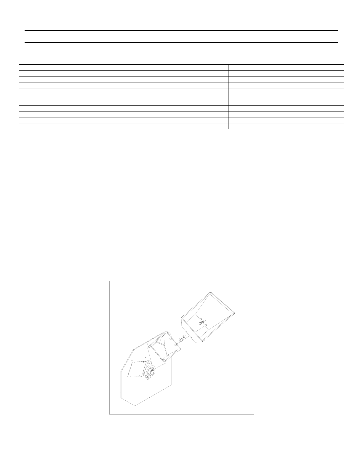
STEP II – ASSEMBLING THE CHIPPER HOPPER
• Assemble chipper hopper to the basic machine using four each 5/16”-18 x ¾” carriage bolts, 5/16”-18 nylock nuts
4 EA – SHREDDER HOPPER
POLYBAG 2 EA – 3/8-16 X 3/8” SET SCREWS 080-0056 PTO SHAFT
2 EA – 5/16-18 X 1 ¼” HHCS 090-0089 SHREDDER HOPPER
2 EA – 5/16-18 X 1 ½” HHCS 090-0090 SHREDDER HOPPER
4 EA – ANTI-VIBRATION MOUNTS 500-0068 SHREDDER HOPPER
and 5/16” flatwashers from the bolt bag. Put head of bolt inside hopper with threads sticking out. Tighten all
hardware with a ½” wrench.
10
Page 11

STEP III – ATTACHING THE SHREDDER HOPPER
• To attach the shredder hopper, push the four vibration dampeners (item #28) up into the mount holes on the
hopper.
• With the vibration dampeners in the hopper mount holes from step 1, place the hopper on top of the unit. NOTE:
the slanted side of the hopper faces the discharge end of the shredder/chipper. Align the holes in the side plates
with the vibration dampeners.
• Push the four bolts up through the side plates and thread them into each vibration dampener until one or two
threads appear. Put the locknuts in place on top of the bolts coming up through the vibration dampeners. Hold the
locknut with a wrench and tighten the bolt until two threads are completely through the nut. DO NOT OVER
TIGHTEN AS THIS WILL DAMAGE THE VIBRATION DAMPENER AND POSSIBLY LEAD TO FURTHER
DAMAGE TO YOUR MACHINE.
11
Page 12

INSTALLATION
• Many tractors permit direct mounting to the lower support pins on the frame of the shredder/chipper. If the lower
hitch arms on your tractor do not have enough inward adjustment to attach to the lower support pins, a pair of pin
extensions may be required to allow proper mounting of the shredder/chipper to the tractor.
• The P.T.O. drive shaft provided with this machine is sized to fit a standard category 1 P.T.O. (1 3/8” x 6 spline).
• The P.T.O. shaft on the tractor that is to use this shredder/chipper must rotate clockwise
P.T.O. from the rear of the tractor. If the P.T.O. rotates counterclockwise, you must have your tractor modified by
installing a gear box to reverse the direction of rotation.
• Depending on the mounting dimensions of the tractor, it may be necessary to have your dealer or yourself modify
the length of the P.T.O. drive shaft that is included with this shredder/chipper. Instructions follow for this
procedure.
• This machine is designed to operate at 540 RPM only. Do not operate at a faster speed that may cause serious
injury to the operator or bystanders and could cause damage to the machine that will not be covered under
warranty.
when viewing the
P.T.O. DRIVE SHAFT MODIFICATION
The P.T.O. drive shaft included with this shredder/chipper may be too long for your tractor. To shorten the driveshaft
proceed as follows.
• Remove the guard.
• Cut the shaft tubes to the required length.
12
Page 13

Round off all edges.
• Shorten the guard tubes to the same length.
• Grease the shaft tubes and reassemble.
REFER TO THE BROCHURE THAT COMES WITH THE P.T.O. DRIVE SHAFT FOR
ADDITIONAL DRIVE SHAFT INFORMATION.
14
Page 14

SECTION III - OPERATION
THIS TRACTOR SHREDDER/CHIPPER ATTACHMENT HAS BEEN DESIGNED TO OPERATE
ON CATEGORY 1 TRACTORS.
THIS MACHINE IS DESIGNED TO OPERATE AT 540 RPM ONLY!
DO NOT OPERATE AT A FASTER SPEED. THIS CAN CAUSE SERIOUS INJURY TO THE
OPERATOR OR BYSTANDERS AND COULD CAUSE DAMAGE TO THE MACHINE THAT
WILL NOT BE COVERED UNDER WARRANTY.
THE SHREDDER/CHIPPER IS DESIGNED TO BE RUN WITH THE WEIGHT OF THE UNIT ON
THE GROUND. SHREDDING OR CHIPPING WITH THE UNIT OFF THE GROUND CAN
RESULT IN INJURY TO YOURSELF OR OTHERS.
Operation Notes
• To activate the shredder/chipper, engage the P.T.O. with the tractor running at idle. Gradually increase
engine speed until you achieve a P.T.O. speed of 540 RPM.
• Proper rotor speed is 2200 RPM +/- 200 RPM.
• When viewed from the operator zone, the rotor and flywheel turn in a clockwise direction. This rotation pulls
branches into the shredder/chipper.
• Always wear protective gloves and safety glasses during operation of the shredder/chipper.
• If it becomes necessary to push material into the chipper hopper, only use a wood stick, never your hands or
anything steel.
• Never assume you know where the knife is. You don’t know where it is. Always keep hands out of all feed
hoppers.
• Keep area of discharge clear of people, animals, buildings, glass or anything else that will obstruct clear
discharge, cause injury or damage.
• If the cutting mechanism strikes a foreign object or if your machine should start making an unusual noise or
vibration, immediately stop the tractor and wait for all moving parts to come to a complete stop. After the
machine has come to a complete stop proceed as follows:
• Inspect for any damage.
• Repair or replace any damaged parts before restarting and operating the machine.
• If the machine should start to vibrate abnormally, immediately stop the tractor and wait for all moving parts to
come to a complete stop and inspect for the cause. Vibration is generally a warning sign of trouble.
• Disengage the P.T.O. drive shaft when leaving the operating position.
• Disengage the P.T.O. when moving the shredder/chipper.
• When feeding material into this equipment, be extremely careful that pieces of metal, rocks, or other foreign
objects are not included. Personal injury or damage to the machine could result.
• Adjust the baffle plate to direct the discharge material down and away from the shredder/chipper. The
discharge end of the machine has three holes for different discharge direction.
• If you shred or chip without any type of screen in place, be certain the baffle plate is held away from the rotor
with one of the screen and baffle rods. Failure to do this will allow the baffle plate to swing backward into the
grinding chamber and become damaged by the rotation of the rotor and hammers.
15
Page 15

SECTION IV – SHREDDING & CHIPPING
THIS SHREDDER/CHIPPER WAS DESIGNED FOR SHREDDING LEAFY GARDEN OR
ORGANIC MATERIAL AND CHIPPING LIMBS OR BRANCHES. NEVER USE THIS MACHINE
FOR ANY OTHER PURPOSE AS IT COULD CAUSE SERIOUS INJURY.
CONTACT WITH INTERNAL ROTATING HAMMERS WILL CAUSE SERIOUS PERSONAL
INJURY. DO NOT PUT HANDS, FACE, FEET OR CLOTHING INTO THE SHREDDER HOPPER,
CHIPPER CHUTE, DISCHARGE OPENING OR NEAR THE DISCHARGE AREA AT ANY TIME.
MAINTENANCE AND SERVICE SHOULD ONLY BE PERFORMED AFTER THE TRACTOR
ENGINE IS OFF, THE P.T.O. DRIVE SHAFT IS DISCONNECTED, AND ALL MOVING PARTS
HAVE COME TO A COMPLETE STOP. USE ONLY A WOODEN STICK TO CLEAR JAMMED
MATERIAL AFTER ALL MOVING PARTS HAVE STOPPED COMPLETELY.
SAFETY FIRST
• Always wear protective gloves and safety glasses during operation of the shredder/chipper.
• Never allow your hands or any part of your body or clothing inside the feed hoppers or
discharge area of the shredder/chipper.
• Keep all protective guards and warning labels on the machine and in good working
condition.
• Always stand clear of the discharge area when the shredder/chipper is running.
• Keep your face and body back from the feed hoppers to avoid being struck by any material
that may bounce back.
• Keep proper balance and footing while operating the shredder/chipper.
• If it becomes necessary to push material into the feed hoppers, only use a wood stick, never
your hands or anything steel.
• Never assume you know where the chipper knife is. You do not know where it is.
• Keep area of discharge clear of people, animals, buildings, glass or anything else that will
obstruct clear discharge, cause injury or damage. Wind can also change discharge
direction, so be aware.
• Always keep hands out of the feed hoppers.
• Never operate the shredder/chipper without the chipper hopper in place.
• Do not transport the shredder/chipper with the P.T.O. engaged.
PROCESSING MATERIAL
• Your shredder/chipper can process dry or green material.
• Green material will process quicker and easier than dry material.
• Soft wood processes easier the hard wood.
• Your operator experience will teach you how different materials shred and chip.
• Your operator experience will teach you how fast you can process different materials.
• Most materials process well with the standard screen.
16
Page 16

• When chipping branches, sometimes a tail will be left at the end of a branch. To avoid this,
rotate the branch as it is fed into the chute.
• Rotating the branch as you feed it into the machine will improve chipping performance.
• Optional screens are available for both greater and less reduction of the material being
processed through the shredder hopper.
USING THE SHREDDER HOPPER
• The shredder hopper is located on the top of the unit and is the opening into which all materials to be shredded
should be fed. Most organic materials can be shredded. A flex guard, or blowback shield is secured to the
hopper. Material must be pushed past this flap using a wooden stick in order to enter the main chipper-shredder
chamber where revolving steel hammers do the shredding. The blowback shield is an important feature. It
prevents kickback of materials! Do not use your machine unless the blowback shield is securely fastened
in place.
• Due to the wide variety of materials that can be shredded, and their very different physical characteristics, only
feed limited quantities of any material into the hopper at first. The amount and length of material can be increased
if you find that the material is being processed without any difficulty. Your judgment and operator experience is
very important. Be sure not to overload the machine by feeding too much material into the hopper at one time. If
you hear the RPM’s decreasing, stop feeding material into the machine at once. Do not resume feeding the
machine until it has returned to full speed.
• The maximum diameter of material that can be shredded is 1 ½”. Any larger material should be fed through the
chipper-hopper. Material larger than 1 ½” can cause serious damage to any of the internal parts of the chippershredder chamber. The unit should be inspected after every use for bent hammers, missing spacers, damage to
the screen or any other obvious problems. If damage occurs, the rotor assembly can become unbalanced causing
excessive vibration. If used in this state, damage can occur. Do not use the machine if vibration is present.
Vibration is generally a warning sign of trouble.
• Several small branches can be fed into the shredder-hopper at once providing their combined diameter is less
than 1 1/2”. Branches longer than three feet should be cut to make them more manageable. Green materials
should be allowed to dry, or processed in small batches with dry materials to avoid winding around the rotor
assembly.
MATERIALS BEST SUITED FOR SHREDDING
• Leaves
• Roots
• Grass clippings
• Straw
• Hay
• Small branches
• Flowers
• Soil
• Garden debris
• Hedge clippings
• Kitchen Waste
• Manure
• Corn Stalks
• Palm frond tops
• Potato vines
• Tomato vines
• Paper
NOTE - The hammers within the chipper-shredder chamber can tug suddenly at material
being fed into the shredder-hopper. Do not hold on tightly to branches and vines, and don’t
feed material straight down into the hopper with your arm pointing downward toward the
opening. Instead, keep your arms parallel to the ground and several inches above the top
edge of the hopper.
17
Page 17

USING THE CHIPPER HOPPER
• This chipper-hopper is mounted on the side of the machine and is designed to chip the larger, heavier materials
that the shredder-hopper isn’t designed to handle. Branches fed into the chute are turned into “chips” by the
revolving chipper knife mounted on a flywheel. The chipper-hopper can chip branches and vines ranging in size
from 1” to 4 ½” in diameter. Cut your materials into manageable lengths before feeding them into the chipper.
Note: The chipper hopper must be securely bolted to the side of your equipment before using the
machine!
• The chipper is designed to draw the complete limbs in through the chipping area. Do not force material into the
chipper. If the machine does not self-feed, the chipper knives need replaced or sharpened or the gap between the
knives and the wear plate needs adjusting.
• Extremely hard knots will not process very well. Short stubs that have not self-fed through the chipper can be
pushed through with the next branch to be chipped. DO NOT THROW REMAINING STUBS OR UNCHIPPABLE
KNOTS INTO THE SHREDDER-HOPPER. DAMAGE WILL RESULT.
• Cut chipping material into manageable lengths of no more than five or six feet long before chipping them.
• Overloading the shredder/chipper will cause the rotor speed to decrease. If you hear the RPM’s decreasing, stop
feeding material into the machine until the machine has returned to full speed.
• Normally the branches will feed themselves into the chipper-hopper if trimmed to an appropriate size. Once the
self-feeding starts, release the branch quickly to avoid ripping from your hands.
MATERIALS BEST SUITED FOR CHIPPING.
• Branches, vines or stalks from 1 ½” to 4 ½” in diameter.
18
Page 18

USE COMMON SENSE WHEN USING YOUR SHREDDER/CHIPPER.
• LEARN TO RECOGNIZE THE CHANGE IN THE SOUND OF YOUR MACHINE
WHEN IT IS OVERLOADED.
• BECOME FAMILIAR WITH SUCCESSFUL OPERATING CONDITIONS AND
AVOID THOSE THAT CAN OVERLOAD AND DAMAGE THE MACHINE.
• IF THE MACHINE BECOMES JAMMED BY OVERLOADING OR ANY OTHER CAUSE,
STOP THE MACHINE IMMEDIATELY.
• IF YOU JAM THE MACHINE AND DO NOT DISENGAGE THE P.T.O., IT CAN DAMAGE
THE MACHINE. THIS DAMAGE CAN BE COSTLY AND IT MAY NOT BE COVERED
UNDER WARRANTY. FOR THIS REASON, IT IS IMPORTANT THAT YOU
IMMEDIATELY DISENGAGE THE P.T.O. IF THE MACHINE BECOMES JAMMED.
• ONLY YOUR OPERATOR EXPERIENCE WILL TELL YOU HOW FAST TO FEED
MATERIAL TO BE PROCESSED.
• CHECK TO SEE THAT THE FLYWHEEL WILL TURN FREELY BEFORE YOU START
THE SHREDDER/CHIPPER.
• VISUALLY CHECK CHIPPER KNIFE FOR DAMAGE EACH TIME YOU USE YOUR
SHREDDER/CHIPPER.
• CHECK KNIFE CONDITION, WEAR PLATE CONDITION, GAP SETTING AND THE
NUTS AND BOLTS THAT HOLD THE KNIFE IN PLACE FOR TIGHTNESS EVERY
8-10 HOURS OF OPERATION.
• DO NOT ALLOW PROCESSED MATERIAL TO BUILD UP WITHIN 3” OF DISCHARGE
CHUTE OPENING. MOVE SHREDDER/CHIPPER OR PILE AS NEEDED. FAILURE TO
DO THIS COULD RESULT IN UNNECESSARY JAMMING OF THE MACHINE.
• TO MOVE PILE OF PROCESSED MATERIAL, USE SPADE, RAKE, OR LONG HANDLE
TOOL. NEVER
USE YOUR HANDS OR FEET!
19
Page 19

SECTION V - MAINTENANCE AND STORAGE
IMPORTANT: The knife should be checked for sharpness and the bolts attaching them to the flywheel for
tightness every 8-10 hours of operation.
IMPORTANT: Every time you perform maintenance or any kind of service or check on the knife, be sure to
check the gap between the knife and wear plate for proper setting.
If the cutting mechanism strikes any foreign object or if your machine should start making an unusual
noise or is vibrating, stop the engine and disconnect the P.T.O shaft before you:
a. Inspect and examine for damage.
1. When not in use, your shredder/chipper should be stored out of the reach of children.
2. After every 8 hours of operation, lubricate the chipper side and drive side bearings. To do this, wipe all dirt, etc.,
3. When the steel chipping knife needs replacing or sharpening, refer to the section on removal, sharpening and re-
4. Care must be exercised when sharpening the knife to maintain the correct bevel and a straight edge. Refer to
b. Repair o replace any damaged parts before restarting and operating the machine.
from the grease fittings with a clean cloth, then apply no more than 3 shots of quality general-purpose grease with
a hand-pumped grease gun. Over lubrication can also damage bearings. Also, check the bearing collar set
screws regularly to be sure they are tight. If they are loose, reset them with Loctite 243, obtainable at any
hardware store.
installation.
sharpening directions. When you install a knife, the clearance between the knife and wear plate must be checked
and set. This clearance or gap should be set to 1/16” (see figure 1).
FLYWHEEL
CHIPPER KNIFE
WEAR PLATE
1/16" GAP
Figure 1
5. To adjust this clearance, loosen the three ¼” nuts and bolts holding the wear plate in place. The wear plate can
be slid up or down (in or out) to achieve the correct gap setting. Tighten the nuts and bolts when the wear plate is
in the correct position. Be certain the flywheel rotates without hitting anything before starting the chipper.
6. If the gap between the wear plate and the knife is not set correctly, you will have excessive vibration when
chipping and the blade will seem to be dull. This should be checked every 8-10 hours of operation.
7. If at any time it becomes necessary to disassemble the chipper for repairs, the chipper disk must be re-installed in
exactly the same position on the rotor shaft.
20
Page 20

REMOVAL, SHARPENING AND RE-INSTALLATION OF CHIPPER KNIFE
HOW TO REMOVE THE KNIFE
• Stop the tractor engine and disengage the P.T.O. driveshaft.
• Open the access cover on the chipper basic machine.
• Rotate the chipper disk until the three countersunk screws attaching the knife to the flywheel are visible
through the access door.
• Clean out the heads of the allen screws with an awl or sharp tool.
• Insert a 3/16” allen wrench into the heads of the screws.
• While applying pressure with the allen wrench, apply heat from a propane torch to the screws to break loose
the Loctite on the screws.
• Remove the heat once the screws have loosened.
• Remove all three allen screws in this manner.
KNIFE SHARPENING
• You should never attempt to sharpen the chipper knife freehand.
• It is extremely important that the 45-degree angle be maintained consistently for proper performance.
• The chipper knife should be taken to a machine shop for proper sharpening.
• Excessive heat generated during the sharpening process will damage knives and weaken the metal. Be sure
the knife is not overheated.
KNIFE INFORMATION
• The chipper knife should be checked routinely for sharpness.
• Using a dull knife will decrease performance and cause excessive vibration that will cause damage to the
shredder/chipper.
• How many times a knife can be sharpened is determined by how much material needs to be taken off to
sharpen or to compensate for dents or gouges.
• A new chipper knife has 5/16” measurement between the short side bevel edge and the knife mounting holes.
See figure 2.
SHORT SIDE BEVEL EDGE
NEW KNIFE
Figure 2
KNIFE MOUNT HOLE
21
Page 21

• The knife should never be sharpened to the extent that more than 3/32” is taken off this measurement.
• Once this measurement is below 7/32” (see figure 3) the knife should be replaced.
• If you are unable to remove dents or gouges with these guidelines, replace the knife.
SHORT SIDE BEVEL EDGE
SHARPENED KNIFE
Figure 3
KNIFE INSTALLATION
• Clean chipper disk where knife is going to be attached.
• Visually inspect the chipper disk slot and knife mounting area and be sure they are clean and that the knife will
be able to mount flush against the chipper disk.
• Visually inspect and clean the knife.
• Apply Loctite 243 to the screws that hold the knife in place.
• Hand tighten the knife to the chipper disk. If you are installing a new knife, use the new hardware that comes
with the knife when attaching it to the chipper disk.
• Tighten the center bolt.
• Tighten the outer bolt.
• Tighten the inner bolt.
• Double-check all three for tightness one more time.
WEAR PLATE
• The wear plate should have a square edge and be free of dents or gouges.
• The wear plate can be sharpened by hand, but as with the knife, do not overheat during the sharpening
process. This will change the characteristics of the steel and it should be replaced.
• Check the gap between the knife and wear plate every time any adjustments are done to either piece, or every
8-10 hours of operation.
22
Page 22

AFTER ANY BLADE OR WEAR PLATE MAINTENANCE OR ADJUSTMENT, ROTATE THE
CHIPPER DISK BY HAND. WATCH AND LISTEN CAREFULLY FOR ANY UNUSUAL NOISES,
CLICKING OR VIBRATION. IF ANY OF THESE ARE DETECTED, INSPECT THE MACHINE
FOR DAMAGE, REPAIR OR REPLACE ANY DAMAGED PARTS AND CHECK FOR ANY
LOOSE PARTS AND RETIGHTEN.
KNIVES MUST BE CHECKED AND MAINTAINED!
KNIVES MUST BE SHARP!
BE SURE TO REINSTALL THE KNIFE CORRECTLY AND DOUBLE CHECK FOR
TIGHTNESS!
HAMMERS
When the hard steel hammers of the rotor assembly become dull or round on the cutting edge, they
may be rotated or reversed. These hammers have four cutting edges that may be used before
replacement is necessary. To reverse the hammers proceed as follows.
• Remove belt guard.
• Remove round cover plate from behind belt guard.
• Remove shredder hopper.
• Remove the top plate.
• Turn rotor assembly until hammer rod is facing up.
• Turn hammer rod until small end of groove pin is facing up.
• Drive the groove pin from the hammer rod with a punch.
• Remove hammer rod through access hole on side of machine.
• Reverse hammers and reinstall with spacers on hammer rod.
• Replace old groove pin with new groove pin.
NOTE: Be sure the hammers and spacers are reinstalled in exactly the order in which they were removed.
Refer to the rotor assembly drawing for the correct order.
23
Page 23

TROUBLESHOOTING
Symptom Problem Correction
Belt burns.
Rotor won’t turn.
Shredding & chipping action
seems too slow or rotor stalling.
When chipping, branch seems to
vibrate excessively & “hammers”
hands.
Machine has excessive vibration. Rotor is out of balance. Check rotor carefully to see if hammers or
Chipper knives move over and
are striking chipper side plate.
Products build-up in shredding
chamber.
Rotor is jammed or stopped. A. Immediately stop engine.
B. Disconnect drive shaft.
C. Remove screen & clean out shredder
chamber.
D. Turn rotor by hand to be sure it turns freely.
E. Check belt tension.
Engine speed is too slow.
Belts are slipping.
Knives are dull.
Gap between blade & wear plate is
too large.
Taper lock bushing is loose.
Set screws in rotor shaft bearings
are loose or missing.
Excessive wear on hammers. Replace or reverse hammers.
Make sure P.T.O. is at 540 RPM.
Check for loose or missing belts & tighten.
Remove blade & sharpen - be sure to maintain
same bevel of 45 degrees.
Adjust gap as per instructions.
spacers are missing.
Replace any damaged or broken hammers.
If key in taper lock bearing is too deep, file key
to seat properly.
Reset the proper blade gap & tighten set
screws.
24
Page 24

Page 25

PARTS LIST
ITEM # PART # QTY DESCRIPTION
1 090-0462 4 5/16-18 X 3/4" CARRIAGE BOLT
2 913-0380 1 CHIPPER HOPPER KIT
3 911-0034 1 SHREDDER HOPPER BLOW BACK GUARD
4 090-0012 3 1/4-20 X 3/4" HHCS
5 911-0049 1 BLOW BACK GUARD MOUNT BAR
6 090-0470 3 1/4-20 NYLOCK NUT
7 911-0028 1 SHREDDER HOPPER WELDMENT
8 090-0460 20 5/16-18 NYLOCK NUT
9 500-0068 4 VIBRATION DAMPENER
10 090-0089 2 5/16-18 X 1-1/4" HHCS
11 090-0090 2 5/16-18 X 1-1/2" HHCS
12 911-0302 1 UPPER SUPPORT WELDMENT
13 090-0370 1 1/2-13 X 3" HHCS
14 911-0296 1 CENTER BRACE
15 090-0110 4 3/8-16 X 1" HHCS
16 090-0461 4 3/8 NYLOCK LOCKNUT
17 090-0050 1 1/2-13 GRIPCO LOCKNUT
18 911-0294 2 LEG
19 090-0088 16 5/16-18 X 1" HHCS
20 911-0295 2 TPH MOUNT BRACKET
21 911-0300 1 BELT GUARD WELDMENT
22 911-0293 1 FRAME WELDMENT
23 911-0150 1 BASIC MACHINE
26
Page 26

Page 27

PARTS LIST
40 900-0040 1 COVER PLATE
41 913-0302 1 SPRING MOUNT BRACKET
42 090-0411 1 1/4-20 X 2-1/2" EYE BOLT
43 030-0329 1 SPRING
44 030-0181 1 BELT
45 030-0180 1 3 GROOVE 3.65" SHEAVE
46 030-0167 1 1-7/16" TAPER LOCK BUSHING
47 020-0001 2 3/8-16 X 5/8" SET SCREWS
48 030-0179 1 3 GROOVE 14" SHEAVE
49 030-0489 1 1" TAPER LOCK BUSHING
50 2 1/2-13 X 1/2" SET SCREWS
51 911-0206 4 MOUNT BAR
52 911-0297 1 LOWER SHAFT
53 030-0055 2 1" BEARING
54 090-0113 2 3/8-16 X 1-3/4" HHCS
55 911-0298 1 IDLER ARM
56 900-0092 2 SPACER
57 090-0461 2 3/8-16 NYLOCK NUT
58 909-0016 1 IDLER SHEAVE
59 911-0054 1 SCREEN
60 911-0033 1 BAFFLE
61 911-0036 2 BAFFLE ROD
62 911-0050 2 3/8-16 X 15" HHCS
28
Page 28

Page 29

Page 30

911-0150 BASIC MACHINE
ITEM # PART # QTY. DESCRIPTION
1
2
3
4
5
6
7
8
9
10
11
12
13
14
15
16
17
18
19
20
21
22
23
24
25
26
27
28
29
30
31
911-0064 1 ROTOR ASSY W/HAMMERS
911-0152 1 CHIPPER SIDE PLATE WLDMNT
911-0268 1 CHIPPER CHUTE PLATE WELDMENT
913-0326 1 WEAR PLATE
030-0279 1 1 3/16" 2 BOLT BEARING
911-0151 1 DRIVE SIDE PLATE
030-0166 1 4 BOLT BEARING 1 7/16" BORE
911-0003 1 SCROLL WELDMENT
911-0026 1 TOP PLATE
911-0267 1 CHIPPER DISK – COMPLETE WITH KNIFE
030-0500 1 CHIPPER KNIFE
030-0167 1 1610 x 1 7/16" ID TAPER LOCK BUSHING
090-0162 4 #10-32 X 3/8 SELF TAPPING SCREW
030-0117 1 RETAINING RING - 1 3/16"
030-0171 2 1 7/16" RETAINING RING
090-0024 1 1.565 OD X 1.192 ID X .050 THK
090-0233 2 5/16"USS FLATWASHER PLTD
090-0111 2 3/8-16 X 1-1/4 HHCS
090-0016 7 3/8-16 X 1 1/2 HHCS GR5 - BLACK
090-0049 12 3/8-16 GRIPCO LOCKNUT GR B PLT
090-0245 3 1/4 SAE FLATWASHER - BLACK
090-0257 3 1/4-20 X 1" SOCKET FLAT HD CAP
090-0470 3 1/4-20 NYLOK LOCKNUT PLTD
090-0463 4 1/2-13 X 1 1/2 HHCS GR5 - BLACK
090-0351 4 1/2 SPLIT LOCKWASHER PLTD
090-0050 4 1/2-13 GRIPCO LOCKNUT GR B PLT
090-0413 3 5/16-18 X 1" FLAT HD SOCKET CAP
090-0066 4 5/16-18 X 3/4 HHCS GR 5 PLTD
090-0048 4 5/16-18 GRIPCO NUT
911-0050 3 3/8-16 X 15"LG HHCS PLTD (TIE ROD)
913-0210 1 ACCESS COVER
911-0064 ROTOR ASSEMBLY
ITEM # PART # QTY. DESCRIPTION
1
2
3
4
5
6
7
911-0135 1 ROTOR WELDMENT
900-0100-4 4 HAMMER ROD
500-0008 48 HAMMER
500-0010 12 SPACER-5/16"
500-0011 24 SPACER-7/8"
500-0012 18 SPACER-5/8"
030-0153 4 13/64" DIA X 1 1/2" LG DRIVE PIN
31
Page 31

COUNTRY HOME PRODUCTS
Megis Road, P.O. Box 25, Vergennes, Vermont 05491
1(800) DR-OWNER (376-9637)
32
 Loading...