

Page 1
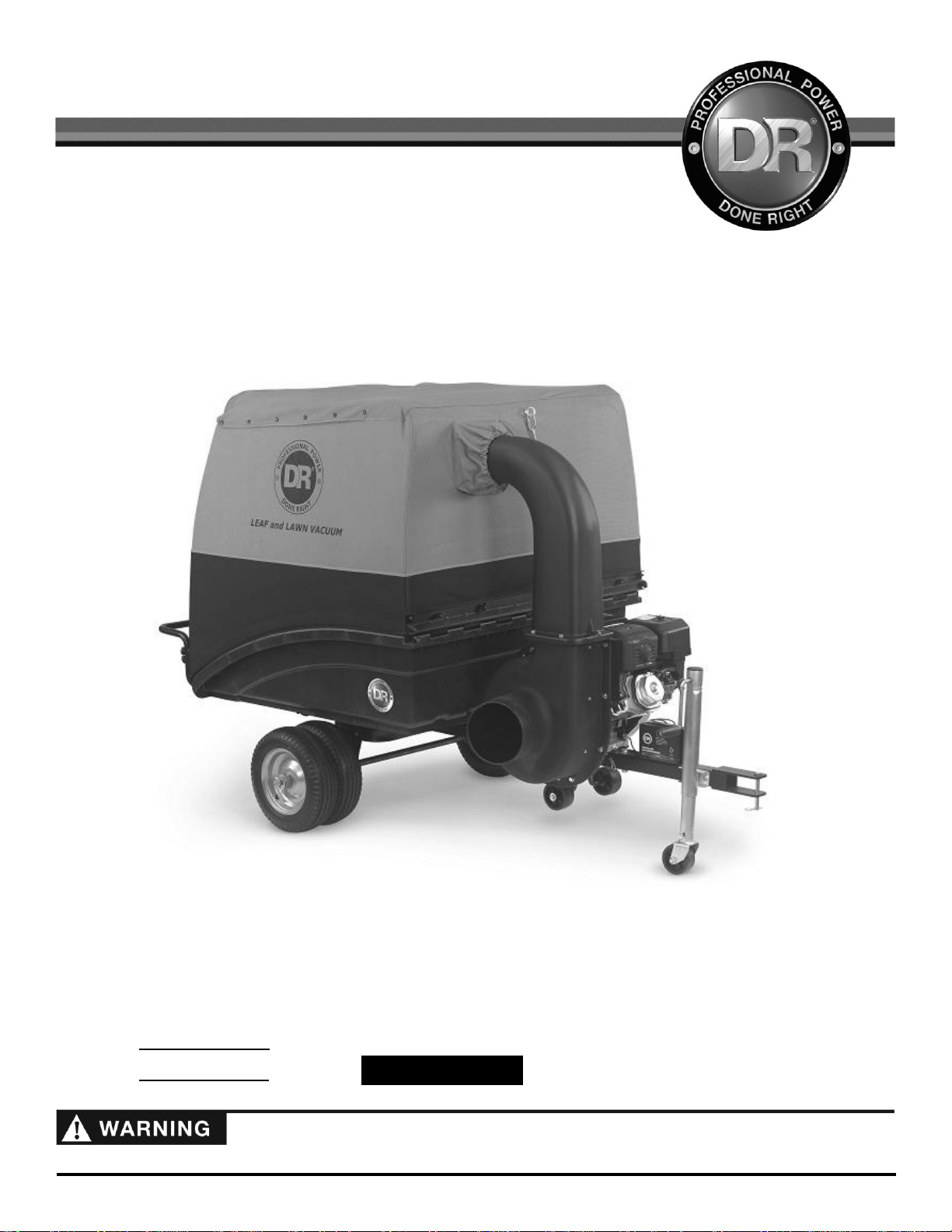
DR® LEAF & LAWN VACUUM
SAFETY & OPERATING INSTRUCTIONS
Models:
- Premier
- Pro
- Pro-XL
Serial No.
Order No.
DR Power Equipment
Toll-free phone: 1-800-DR-OWNER (376-9637)
Fax: 1-802-877-1213
Website: www.DRpower.com
Pro-XL Model Shown
Read and understand this manual and all instructions before operating the DR LEAF and LAWN VACUUM.
Original Language
CONTACT US AT www.DRpower.com 1
Page 2

This indicates a hazardous situation, which, if not avoided, could result in death or serious injury.
Table of Contents
This information is important in the proper use of your machine. Failure to follow this instruction could result in damage to
your machine or property.
This indicates a hazardous situation, which, if not avoided, could result in minor or moderate injury.
Chapter 1: General Safety Rules ............................................................................................................................................................ 3
Chapter 2: Setting Up The DR LEAF and LAWN VACUUM ................................................................................................................. 7
Chapter 3: Operating The DR LEAF AND LAWN VACUUM ................................................................................................................ 22
Chapter 4: Maintaining The DR LEAF and LAWN VACUUM............................................................................................................... 27
Chapter 5: Troubleshooting .................................................................................................................................................................. 34
Chapter 6: Parts Lists, Schematic Diagrams And Warranty ................................................................................................................ 36
Conventions used in this manual
Serial Number and Order Number
A Serial Number is used to identify your machine and is located on the Serial Number Label on your machine. An Order Number
is used to check and maintain your order history and is located on the upper left portion of your packing slip. For your
convenience and ready reference, enter the Serial Number and Order Number in the space provided on the front cover of this
manual.
Additional Information and Potential Changes
DR Power Equipment reserves the right to discontinue, change, and improve its products at any time without notice or obligation
to the purchaser. The descriptions and specifications contained in this manual were in effect at printing. Equipment described
within this manual may be optional. Some illustrations may not be applicable to your machine.
2 DR
®
LEAF and LAWN
Page 3
Read this safety & operating Instructions manual before you use the DR LEAF and LAWN VACUUM. Become familiar with the
operation and service recommendations to ensure the best performance from your machine. If you have any questions or need
assistance, please contact us at www.DRpower.com or call toll-free 1-800-DR-OWNER (376-9637) and one of our Technical
Support Representatives will be happy to help you.
Chapter 1: General Safety Rules
#13758
#18887
#15342
#34278
#34279
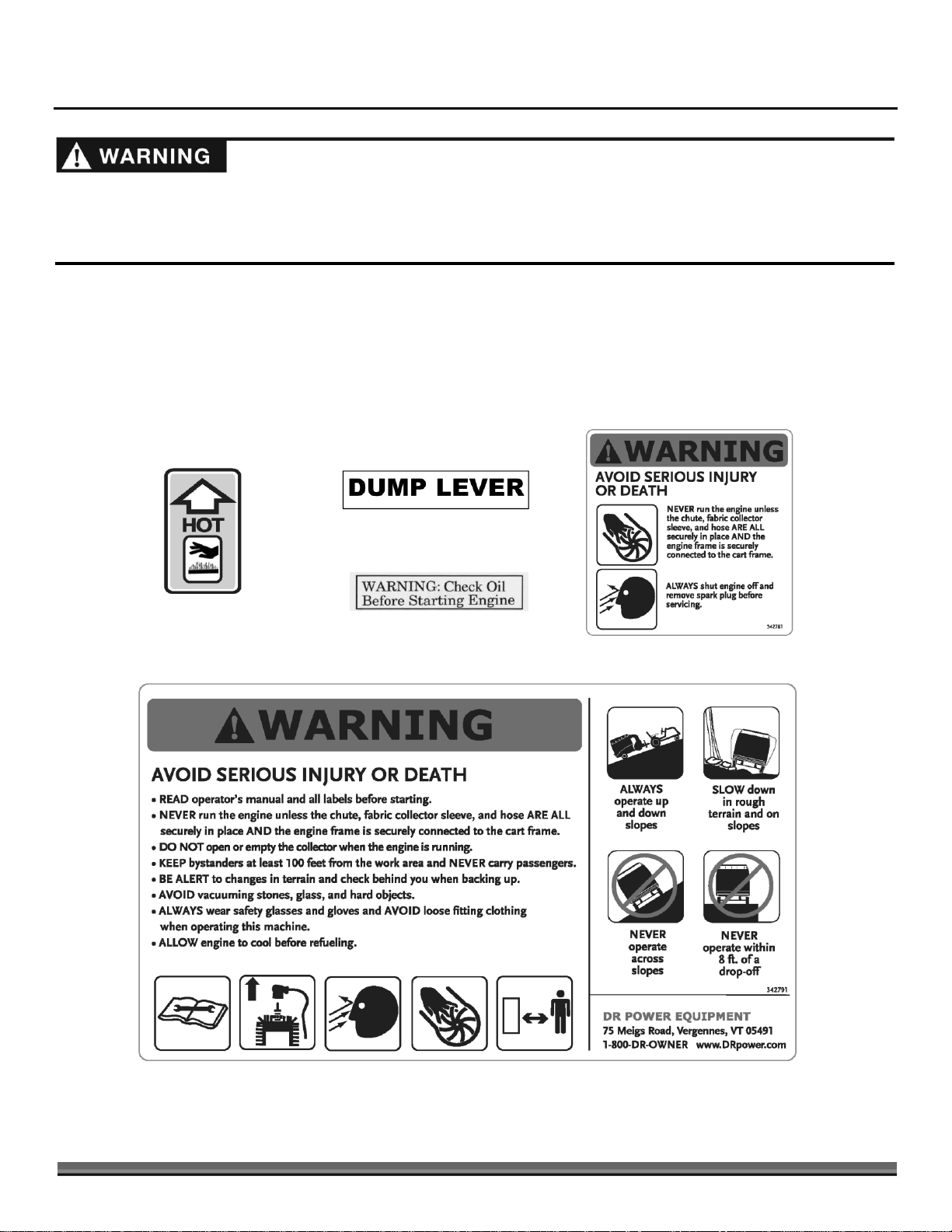
Labels
Your DR LEAF and LAWN VACUUM carries prominent labels as reminders for its proper and safe use. Shown below are copies of
all the Safety and Information labels that appear on the equipment. Take a moment to study them and make a note of their
location on your machine as you set up and before you operate the unit. Replace damaged or missing safety and information
labels immediately.
CONTACT US AT www.DRpower.com 3
Page 4

Protecting Yourself and Those Around You
Gasoline is a highly flammable liquid. Gasoline also gives off flammable vapor that can be easily ignited and cause a fire or
explosion. Never overlook the hazards of gasoline. Always follow these precautions:
Never run the engine in an enclosed area or without proper ventilation as the exhaust from the engine contains carbon
monoxide, which is an odorless, tasteless, and deadly poisonous gas.
Store all fuel and oil in containers specifically designed and approved for this purpose and keep away from heat and open
flame, and out of the reach of children.
Replace rubber fuel lines and grommets when worn or damaged and after 5 years of use.
Fill the gasoline tank outdoors with the engine off and allow the engine to cool completely. Don't handle gasoline if you or
anyone nearby is smoking, or if you're near anything that could cause it to ignite or explode. Reinstall the fuel tank Cap and
fuel container cap securely.
Tragic accidents can occur if the operator is not alert to the presence of children and pets. Children and pets are often attracted to
the machine and the vacuuming activity.
Never
assume that children or pets will remain where you last saw them. Always follow
these precautions:
Keep children and pets at least 100 feet from the working area and ensure they are under the watchful care of a responsible
adult.
Be alert and always turn off the lawn tractor engine and the DR Leaf and Lawn Vacuum engine if children or pets enter the
work area.
Before and while moving backwards, look behind, and
down
for small children and pets. You cannot see directly behind the
collector box.
Never allow children to operate the Lawn Tractor or Vacuum.
Never allow children or pets to play in the collector. If they become trapped in the enclosure they may be exposed to
temperatures similar to leaving a child or pet in a car with the windows closed on a sunny day.
Use extra care when approaching blind corners, shrubs, trees, or other objects that may obscure your vision.
This is a high-powered machine, with moving parts operating with high energy at high speeds. You must use proper clothing and
safety gear when operating this machine to prevent or minimize the risk of severe injury. This machine can cut, and sever parts of
your body if they become in contact with the moving impeller blades. Always take the following precautions when operating this
machine:
Always wear protective goggles or safety glasses with side shields while operating either your tractor lawn deck, the vacuum
system, or when performing an adjustment on your DR Leaf and Lawn Vacuum to protect your eyes from possible foreign
objects thrown from the machine.
Avoid wearing loose clothing or jewelry, which can catch on the machine’s moving parts.
We recommend wearing gloves while using the DR Leaf and Lawn Vacuum. Be sure your gloves fit properly and do not have
loose cuffs or drawstrings.
Wear shoes with non-slip treads when using your DR Leaf and Lawn Vacuum. If you have safety shoes, we recommend
wearing them. Do not use the machine while barefoot or wearing open sandals.
Wear long pants while operating the DR Leaf and Lawn Vacuum.
Use ear protectors or earplugs rated for at least 20 dba to protect your hearing.
Safety for Children and Pets
Safety with Gasoline - Powered Machines
4 DR
®
LEAF and LAWN
Page 5

Slope Operation
This is a high-powered machine, with moving parts operating with high energy at high speeds. You must operate the machine
safely. Unsafe operation can create a number of hazards for you, as well as anyone else in the nearby area. Always take the
following precautions when using this machine:
Never allow people who are unfamiliar with these instructions to use the DR Leaf and Lawn Vacuum.
To be safe, do not operate the machine near small children or pets, and never allow children to operate the vacuum. Stop the
vacuum engine and tractor engine when another person or pet approaches.
Never allow people or pets to ride in the collector box or on the frame.
If you spill gasoline, do not attempt to start the engine. Move the machine away from the area of the spil l and avoid creating
any source of ignition until the gas vapors have dissipated. Wipe up any spilled fuel to prevent a fire hazard and properly
dispose of the waste.
Allow the engine to cool completely and empty the collector box before storing the DR Leaf and Lawn Vacuum in any
enclosure. Remember, decomposing material can generate heat and start a fire. Never store the machine with gas in the
tank or a fuel container, near an open flame or spark such as a water heater, space heater, clothes dryer or furnace.
Never make adjustments or repairs with the engine running. Shut down the engine, disconnect the spark plug wire, keeping it
away from the spark plug to prevent accidental starting, wait 5 minutes before making adjustments or repairs.
Never tamper with the engine’s governor setting. The governor controls the maximum safe operation speed and protects the
engine. Over-speeding the engine is dangerous and will cause damage to the engine and to the other moving parts of the
machine. If required, see your authorized dealer for engine governor adjustments.
Keep your hands and combustible substances away from the engine when it is hot and clean the engine area after each use.
To reduce fire hazard, keep the engine cooling fins and muffler area free of debris build-up such as leaves, grass, oil, grease or
any other combustible material.
Never cover the machine while the muffler is still hot.
Do not operate the engine with the air cleaner or the carburetor air intake cover removed, except for adjustment. Removal of
such parts could create a fire hazard.
Do not use flammable solutions to clean the air filter.
The muffler and engine become very hot and can cause a severe burn; do not touch.
The exhaust area on the engine becomes very hot with use. Allow the engine to cool before doing maintenance or making
adjustments.
Slopes are a major factor related to tip over accidents, which can result in severe injury. All slopes require caution. If you feel
uneasy on a slope, do not vacuum it. Always take the following precautions when using this machine on slopes:
ALWAYS:
Vacuum up and down the face of slopes, never across. Exercise extreme caution when changing direction on slopes.
Remove objects such as stones, glass and metal objects such as cans.
Watch out for holes, ruts, or bumps. Tall grass can hide obstacles.
NEVER:
Never vacuum near drop-offs, ditches, or embankments. Your tractor and the vacuum may tip over.
Never vacuum on slopes greater than 15 degrees or any excessively steep slopes.
Never vacuum on wet slopes. Reduced traction could result in slipping and a possible roll over.
General Safety
CONTACT US AT www.DRpower.com 5
Page 6

Never run the engine unless the chute, fabric collector sleeve, and hose are all securely in place and the engine frame is
securely connected to the cart frame.
Check behind your DR Leaf and Lawn Vacuum before backing up. You cannot see directly behind the collector box.
Never attempt to open or empty the collector while the lawn tractor deck is engaged or the DR Leaf and Lawn Vacuum engine
is running. Debris may exit at high velocity as you begin to open the collector.
Do not operate in sandy areas where you will vacuum large quantities of sand. Sand will erode the vacuum housing. Check
for holes after each use and replace the housing and liner when holes develop.
Never operate the machine on slopes greater than 15 degrees.
Never tow the DR Leaf and Lawn Vacuum faster than 8 mph.
Always shut off the lawn tractor engine and the DR Leaf and Lawn Vacuum engine and disconnect the spark plug wire before
attempting to clear any obstructions from the hose.
Use the DR Leaf and Lawn Vacuum only in daylight.
Never straddle or reach over the engine area at any time.
Use only your hands to operate the DR Leaf and Lawn Vacuum engine controls.
Do not, under any conditions, remove, bend, cut, fit, weld, or otherwise alter standard parts on the DR Leaf and Lawn
Vacuum. Modifications to your machine could cause personal injuries and will void your warranty.
Do not alter or tamper with safety devices or shields. Make sure they are in their proper position.
While using the DR Leaf and Lawn Vacuum, do not hurry or take things for granted.
Never leave the DR Leaf and Lawn Vacuum unattended with its engine running.
Do not operate the machine when under the influence of alcohol, drugs, or medication.
The DR Leaf and Lawn Vacuum must be operated safely to prevent or minimize the risk of minor or moderate injury. Unsafe
operation can create a number of hazards for you. Always take the following precautions when operating this machine:
Keep in mind that the operator or user is responsible for accidents or hazards occurring to other people, their property, and
themselves.
Never use the DR Leaf and Lawn Vacuum to vacuum anything but yard waste, such as leaves, grass, small twigs and pine
cones.
If the machine starts to make an unusual noise or vibration, immediately shut off the engine, disconnect the spark plug wire,
and allow all moving parts to come to a complete stop and cool. Inspect for clogging or damage. Clean and repair and/or
replace damaged parts.
See manufacturer’s instructions for proper operation and installation of accessories. Only use accessories approved by DR
Power Equipment.
Always keep the equipment in a good safe operating condition. Always make certain nuts and bolts are tight and always use
the supplied self-locking hardware; do not substitute.
A Note to All Users
Under California law, and the laws of some other states, you are not permitted to operate an internal combustion engine using
hydrocarbon fuels without an engine spark arrester. This also applies to operation on US Forest Lands. All DR® LEAF and LAWN
VACUUMS shipped to California, New Mexico and Washington State are provided with spark arresters. Failure of the owner or
operator to maintain this equipment in compliance with state regulations is a misdemeanor under California law and may be in
violation of other state and/or federal regulations. Contact your State Park Association or the appropriate state organization for
specific information in your area.
No list of warnings and cautions can be all-inclusive. If situations occur that are not covered by this manual, the operator must
apply common sense and operate this DR® LEAF and LAWN VACUUM in a safe manner. Contact us at www.DRpower.com or
call 1-800-DR-OWNER (376-9637) for assistance.
6 DR
®
LEAF and LAWN
Page 7
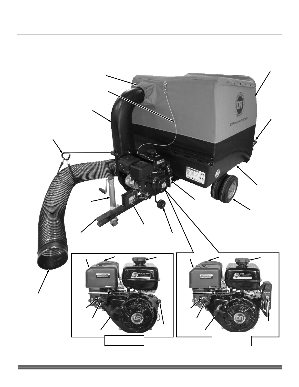
Chapter 2: Setting Up the DR LEAF and LAWN VACUUM
Collector Sleeve
Hose Support
Dump
Lever
Collector
Outlet
Chute
Cart Bed
Power Unit
Wheels
Figure 1
Pneumatic
Tires
Tow Hitch
Dump
Handle
Jack
Battery (Electric
Start Models)
Manual start)
On/Off
Switch
Choke
Air Filter
Gas Shut-Off
Starter Recoil Handle
Key
Switch
Gas Fill
Inlet Hose with Cuff
Cable
Electric start)
Muffler
Throttle
Choke
Air Filter
Gas Shut-Off
Starter Recoil Handle
Gas Fill
Muffler
Throttle
It may be helpful to familiarize yourself with the controls and features of your DR LEAF and LAWN VACUUM as shown in Figure 1
before beginning these procedures. If you have any questions at all, please feel free to contact us at www.DRpower.com.
DR LEAF and LAWN VACUUM Controls and Features
CONTACT US AT www.DRpower.com 7
Page 8
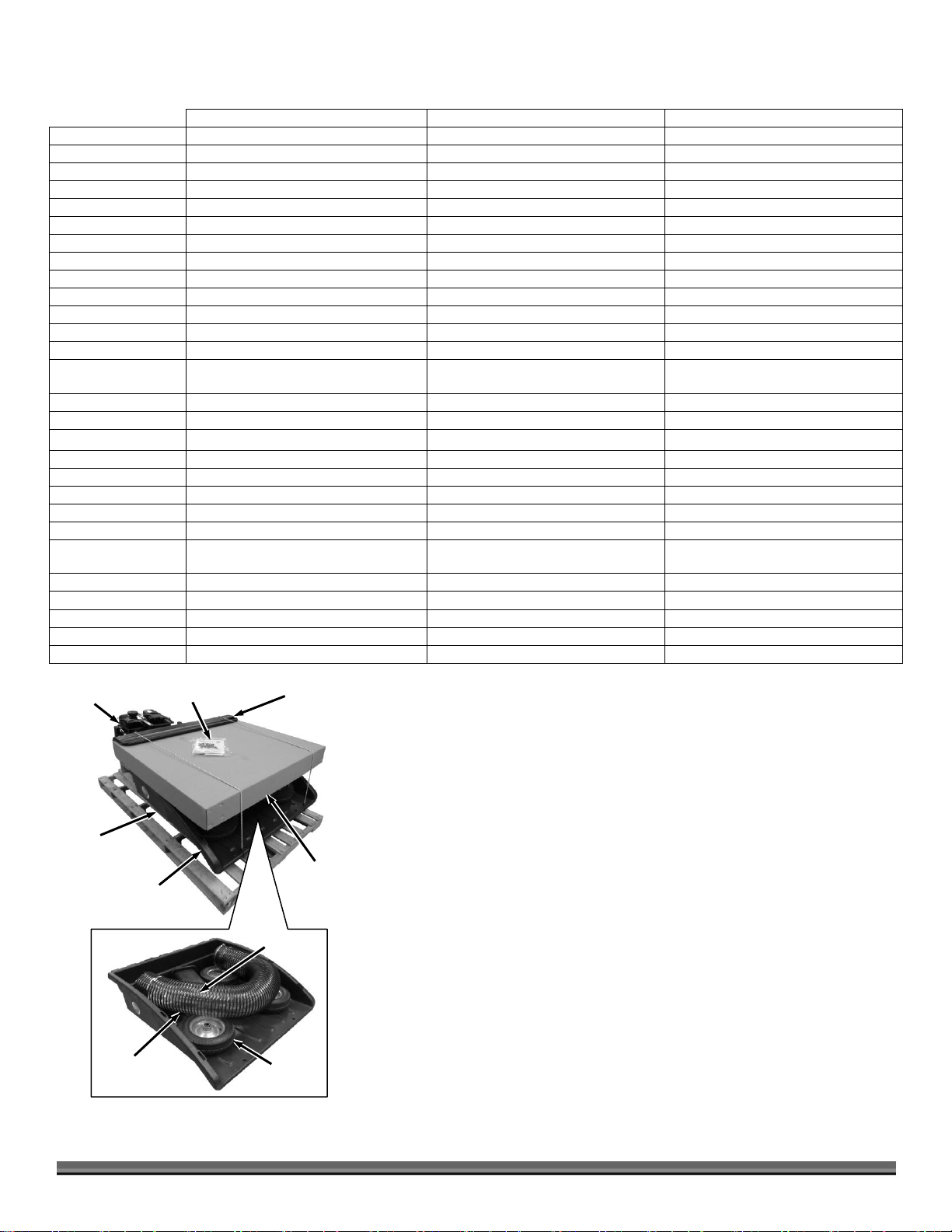
Axle
(Under Cart)
Wheels
Figure 2
Inlet Hose
Outlet Chute
Power Unit
Tube Frame
Handle
Cart with
Frame
Product
Package
Large
Parts Box
Specifications
PREMIER
PRO
PRO-XL
Engine
DR Power Equipment R225
DR Power Equipment R300
DR Power Equipment R390
Ft-lbs Torque
9.59
13.28
16.96
Starting
Manual or Electric w/ Recoil Backup
Manual or Electric w/ Recoil Backup
Manual or Electric w/ Recoil Backup
RPM
3800
3800
3800
Impeller
Steel, 5 Blades w/Serrated Teeth
Steel, 5 Blades w/Serrated Teeth
Teel, 5 Blades w/Serrated Teeth
Weight
13.2 Lbs
13.2 Lbs
13.2 Lbs
Mount
Keyless Tapered Direct Engine Mount
Keyless Tapered Direct Engine Mount
Keyless Tapered Direct Engine Mount
Vacuum
2038 CFM
2237 CFM
2237 CFM
Suction
66 MPH
72 MPH
72 MPH
Hose
8" ID
8" ID
8" ID
Collector
Clamshell Design
Clamshell Design
Clamshell Design
Volume
27 Cuft, 200 Gallons
43 Cuft, 321 Gallons
43 Cuft, 321 Gallons
Capacity
500 Lbs
800 Lbs
800 Lbs
Fabric Enclosure
1800 Denier Polyester with Bonded
PVC Backing
1800 Denier Polyester with Bonded
PVC Backing
1800 Denier Polyester with Bonded
PVC Backing
Dump Tilt
60°
60°
60°
Cart
Detachable, High Strength PE Cart Bed
Detachable, High Strength PE Cart Bed
Detachable, High Strength PE Cart Bed
Frame
Welded Steel, 2 Piece Modular Design
Welded Steel, 2 Piece Modular Design
Welded Steel, 2 Piece Modular Design
Impeller Housing
Steel Side w/High Impact HDPE Scroll
Steel Side w/High Impact HDPE Scroll
Steel Side w/High Impact HDPE Scroll
Scroll Liner
.1" Thick Steel
.1" Thick Steel
.1" Thick Steel
Wheels
Pneumatic 5.30/4.50-8 4 Ply w/ Tube
Pneumatic 5.30/4.50-8 4 Ply w/ Tube
Pneumatic 5.30/4.50-8 4 Ply w/ Tube
Quantity
2 (1 Per Side)
4 (2 Per Side)
4 (2 Per Side)
Tire Size
14" Diameter x 4.5" Wide
14" Diameter x 4.5" Wide
14" Diameter x 4.5" Wide
Jack
Optional Accessory
Heavy Duty w/ 4" Wheel (Ships
installed)
Heavy Duty w/ 4" Wheel (Ships
installed)
Lawn Mower
12 HP Min Flat Terrain otherwise 14 HP
14 HP Min
14 HP Min
Lawn Mower Hitch
Pin Hitch 8" to 15" from the Ground
Pin Hitch 8" to 15" from the Ground
Pin Hitch 8" to 15" from the Ground
Battery (E/S Models)
9Ah, Spade Terminals
9Ah, Spade Terminals
9Ah, Spade Terminals
Dimensions
87.8" L x 40.1" W x 52.6" H
87.8" L x 49.5" W x 58.6" H
87.8" L x 49.5" W x 58.6" H
Weight
231 Lbs M/S, 243 Lbs E/S
299 Lbs M/S, 311 Lbs E/S
313 Lbs M/S, 325 Lbs E/S
8 DR
®
LEAF and LAWN
Parts supplied on Pallet (Figure 2):
Power Unit
Cart Bed with Frame
Axle
Tube Frame Handle
Product Package
o Safety and Operating Instructions Manual
o Engine Manual
o Hardware (see figure 3)
Large Parts Box (see Figure 4)
Parts in Cart Bed:
o 2 Wheels (Premier)
o 4 Wheels (Pro and Pro XL)
o Inlet Hose
o Outlet Duct
Page 9
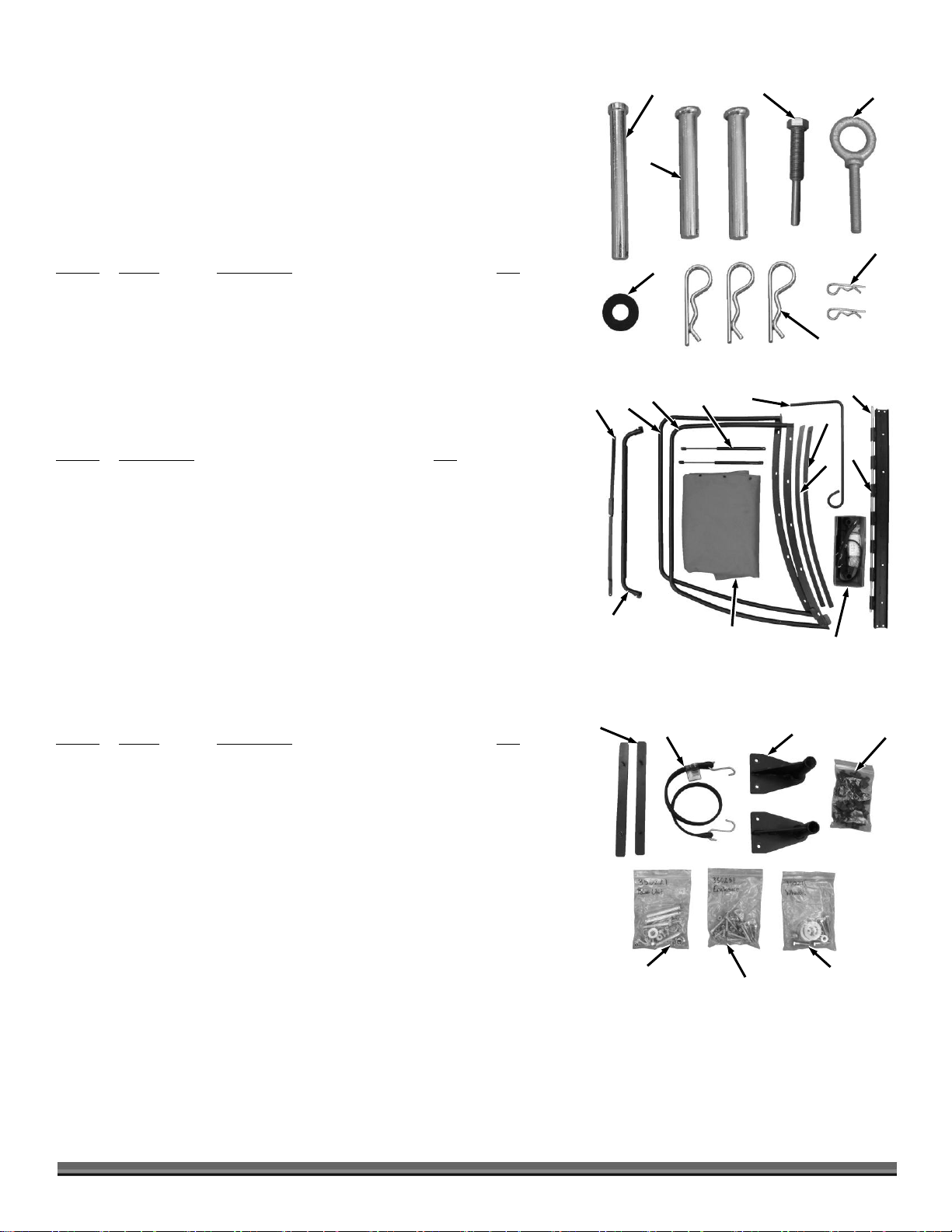
Assembly Parts Identification
1
Figure 3
2 4 5 6 3 7 1
Figure 5
2
4 7 3
6 5 1
Figure 4
6 2 4
5
9
Small Parts Box
8
11 3 10
7
Compare the contents of the Parts Boxes and Hardware Packages with the Parts
Supplied lists and Figures 3 thru 8 below. If there are any questions contact us
at www.DRpower.com or call 1-800-DR-OWNER (376-9637).
There may be hardware left over when assembly is finished. This is sometimes
expected in the process of filling hardware bags at the factory.
Product Package Hardware (Figure 3):
Item # Part # Description Qty
1 ............. 18737 .............. Pin, Clevis, 1/2" X 4.5", ZP ............................ 1
2 ............. 21154 .............. Pin, Clevis, 1/2" X 3.5", ZP ............................ 2
3 ............. 35037 .............. Bolt, Hex, 7/16-20, Impeller Tool .................. 1
4 ............. 35028 .............. Eyebolt, 5/16-18 X 2", Forged, ZP .................. 1
5 ............. 33787 .............. Pin, Cotter, Hair, 1/4-3/8 ............................... 2
6 ............. 16003 .............. Pin, Hitch Clip 1/2" ........................................ 3
7 ............. 18967 .............. Washer, Flat, 1/2", Rubber............................. 1
Large Parts Box Contents (Figure 4):
Item # Description Qty
1 ............. Link Assembly ........................................................ 1
2 ............. Tube Frame, Collector, LH ...................................... 1
3 ............. Tube Frame, Collector, RH ..................................... 1
4 ............. Gas Spring, 500-300 mm, 150 lb ............................ 2*
5 ............. Rod, Support, Hose................................................. 1
6 ............. Retainer, Enclosure, RH .......................................... 1
7 ............. Retainer, Enclosure, LH .......................................... 1
8 ............. Pin, Hinge ....... ........................................................ 1
9 ............. Hinge, Tube Frame ................................................. 1
10 ........... Enclosure, Fabric ..................................................... 1
11 ........... Tube Frame, Collector, Top .................................... 1
*Only one Gas Spring used for Premier
Small Box Parts (Figure 5):
Item # Part # Description Qty
1 ............. 33791 .............. Retainer, Enclosure, Front ............................. 2
2 ............. 35442 .............. Strap and Hook Set ........................................ 1
3 ............. 33802 .............. Bracket, Axle ................................................... 2
4 ............. 35029 .............. Knob Set, 5/16-18 W/Lock, 17 Pack .............. 1
5 ............. 35022 .............. Hardware Set, Power Unit ............................. 1
6 ............. 35025 .............. Hardware Set, Enclosure................................ 1
7 ............. 35021 .............. Hardware Set, Wheels .................................... 1
CONTACT US AT www.DRpower.com 9
Page 10
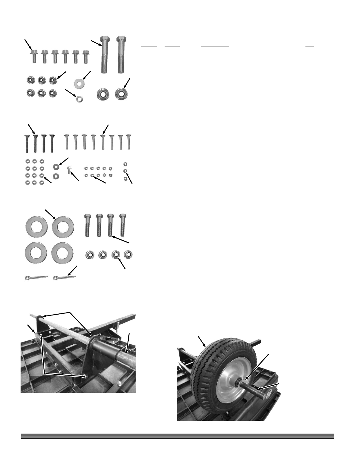
Power Unit Hardware (Figure 6):*
1
Figure 6
2
3
4 6 5
1
Figure 7
2
3
4
6 5 7
1
Figure 8
2
3
4
Axle Brackets
Figure 9
Frame
Axle
Hardware
Axle
1st Dual Wheel (Valve Stem and
Grease Fitting facing in)
Figure 10
Large Washer
Item # Part # Description Qty
1 ............. 35023 .............. Bolt, Hex, Flange, 5/16-18 X .75" .................. 6
2 ............. 26556 .............. Bolt, HCS, 1/2-13 X 2.75", GR5, ZP............... 2
3 ............. 33335 .............. Nut, Nylon Lock, Flange, 1/2-13 ................... 2
4 ............. 11241 .............. Washer, Flat, 5/16" USS, ZP.......................... 1
5 ............. 11243 .............. Washer, Lock, 5/16", Split, ZP ....................... 1
6 ............. 33332 .............. Nut, Nylon Lock, Flange, 5/16-18 ................. 6
Enclosure Hardware (Figure 7):*
Item # Part # Description Qty
1 ............. 35026 .............. Bolt, C-Head, 5/16-18 X 2.5", ZP.................... 4
2 ............. 35027 .............. Bolt, C-Head, 5/16-18 X 1.75", ZP.................. 8
3 ............. 11076 .............. Nut, Nylon Lock, 5/16-18, ZP ......................... 3
4 ............. 11073 .............. Nut, Nylon Lock, 1/4-20, ZP ........................... 10
5 ............. 35023 .............. Bolt, Hex, Flange, 5/16-18 X .75 ..................... 1
6 ............. 11241 .............. Washer, Flat, 5/16 USS, ZP ............................ 2
7 ............. 27905 .............. Push Nut, 5/16" .............................................. 12
Wheel Hardware (Figure 8):*
Item # Part # Description Qty
1 ............. 35039 .............. Washer, 1.06" ID X 2" OD X .13", ZP............. 4
2 ............. 12334 .............. Bolt, HCS, 3/8-16 X 1.75", GR5, ZP ............... 4
3 ............. 33333 .............. Nut, Nylon Lock, Flange, 3/8-16 .................... 4
4 ............. 12685 .............. Pin, Cotter, 3/16" X 1.5" ................................. 2
*Above Sets include some extra hardware.
Installing the Wheels (Use Wheel Hardware Package, see Figure 8)
Tools Needed:
Two 9/16" Wrenches
Pliers
1. Tip the Cart over to access the Frame (Figure 9).
2. Install the Axle Brackets and loosely secure with the Bolts and Locknuts
using two 9/16" Wrenches.
3. Slide the Axle through the Brackets until the same amount sticks out on the
side. Tighten the hardware.
4. For Machines with Dual Wheels: Slide a Wheel onto the end of the Axle with
the Valve Stem facing in and install a Washer against the Wheel (Figure 10).
10 DR
®
LEAF and LAWN
Page 11
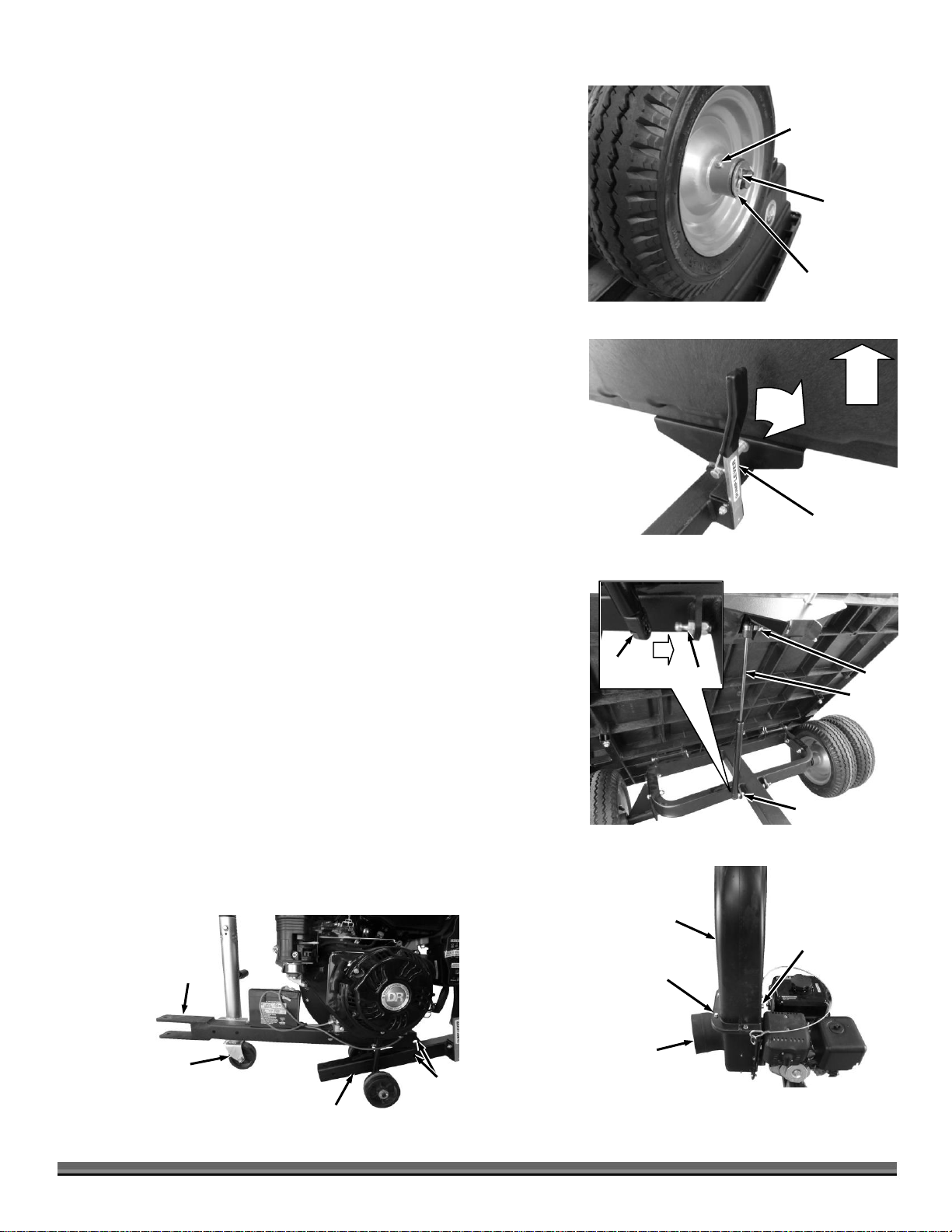
5. Install a Wheel (second wheel for Dual Wheel models) with the Valve Stem
Dump Lever
Figure 12
1
2
2nd Dual Wheel
or single Wheel
(Valve Stem and
Grease Fitting
facing out)
Figure 11
Washer
Cotter Pin
Jack
(Standard Equipment
on Pro and ProXL)
Figure 15
Cart Frame
Rear
Holes
Tow
Hitch
Outlet Chute
Figure 14
Impeller
Housing
Bolts and
Locknuts
Bolt, Lock Washer
and Flat Washer
Gas
Spring
Figure 13
Stud
Stud
Stud
Gas
Spring
facing out and place a Washer against the Wheel (Figure 11).
6. Secure the Wheel/s onto the Axle with a Cotter Pin. Use Pliers to bend the
ends of the Cotter Pin to secure the Wheels.
7. Repeat for the Wheel/s on the opposite side.
8. Tip the Cart over onto the Wheels.
Installing the Gas Spring/s
Note: The Premier uses one Gas Spring. The Pro and ProXL use two Gas Springs.
1. Tilt the Cart Bed up by pulling the Lift Handle out and lifting up on the front
of the Cart (Figure 12).
Note: In the next step, the Gas Spring needs to be installed with the larger end
attached to the Frame and the thin Shaft end to the Cart Bed.
2. Insert the right side Gas Spring onto the Studs by pressing the holes in the
ends of the Gas Spring over the Studs. They will snap into place. (Figure 13).
3. For Pro and ProXL: Do not install the second Gas Spring at this time.
4. Leave the Cart in the up position for the following procedure.
Installing the Power Unit (Use Power Unit Hardware Package, see
Figure 6)
Tools Needed:
Two 9/16" Wrenches
Two 3/4" Wrenches
Flat Head Screwdriver or 5/16" Wrench
1. Place the Outlet Chute on top of the Impeller Housing and loosely install the
Engine side with a 5/16-18 X .75" Bolt, Lock Washer and Flat Washer using a
9/16" Wrench (Figure 14).
2. Secure the flange of the Outlet Chute and Impeller Housing with four 5/16-
18 X .75" Bolts and 5/16-18 Locknuts using two 9/16" Wrenches. For proper
alignment, tighten the two flange Bolts nearer the engine first, then tighten
the rest of the hardware.
3. Machines with Jacks: Remove the Locking Pin from the lower portion of the
Jack and crank the Jack Handle so the Power Unit Tow Hitch is lowered as far
as it will go towards the ground (Figure 15).
4. Move the Engine unit into position at the front of the Cart with the Tow Hitch
facing forward and
the rear holes
aligned.
CONTACT US AT www.DRpower.com 11
Page 12
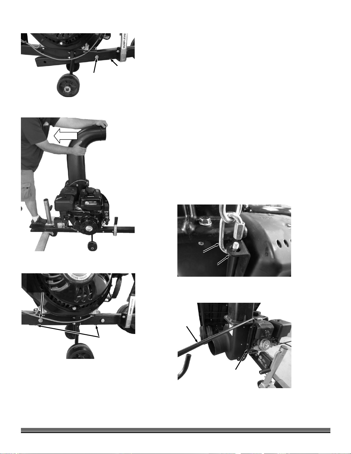
5. Lift the Cart Frame to align the rear hole in the Engine Unit with the hole in
Cable Link
Figure 19
Impeller Housing
Bracket
Clevis Pin and
Hitch Clip (From
Product Package)
Figure 16
Trailer
Frame
Figure 17
Figure 18
2nd Clevis
Pin and
Hitch Clip
Bolts (Heads
on Bottom)
and Locknuts
Hose
Support
Figure 20
Impeller
Housing
Bracket
the Frame and insert a 1/2" X 3.5" Clevis Pin and Hitch Clip (Clevis Pins and
Hitch Clips are provided in the Product Package) (Figure 16).
6. Chock the Wheels of the Cart to keep it from moving and have a helper pull
forward on the Outlet Chute so the Power Unit and Cart Frame front holes
are aligned (Figure 17).
Note: If you have a Floor Jack or similar you could jack under the Dump Lever to
align the Frames without a helper.
7. Insert the 2nd 1/2" X 3.5" Clevis Pin and Hitch Clip into the front holes of
the Engine Unit and Cart Frame (Figure 18).
8. Place the two 1/2-13 X 2.75" Bolts from underneath up through the two
vertical Holes and secure with 1/2-13 Locknuts using two 3/4" Wrenches.
Remove the Jack if one was used.
9. Unhitch the Cable Link from the Impeller Housing Bracket by turning the
hex portion of the link to open it up (Figure 19).
10. Slide the Hose Support into the Impeller Housing Bracket holes (Figure 20).
12 DR
®
LEAF and LAWN
Page 13
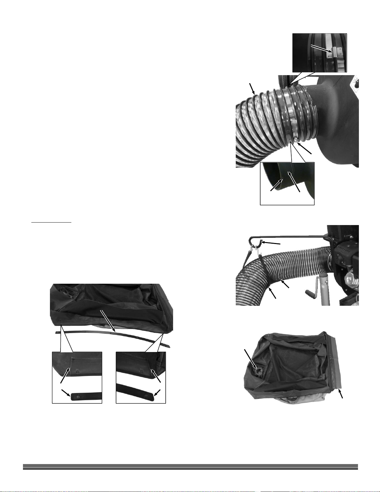
Figure 24
Front
Rear
Right Side Enclosure
Retainer (Studs
Facing Up)
Square
Angle
11. Using a Flat Head Screwdrive or 5/16" Wrench, loosen the Hose Bridge
Front
Sleeve
Figure 23
Rear Flaps
Inner Enclosure
(Black)
Inlet Hose
Figure 21
Clamp
Hose Bridge
Clamp
Retaining
Bump
Clamp
Area
Hose
Figure 22
Rubber Strap
Hose Support
Clamp, slide the hose onto the Housing neck, and tighten the Hose Bridge
Clamp very tightly (Figure 21).
Note: Make sure the Hose Bridge Clamp is past the Retaining Bumps on the
Housing.
12. Support the Hose with the Rubber Strap by hooking one end into the Support
Loop, going under the Hose and securing the other end onto the Support
Loop (Figure 22).
Collector Assembly (Use Enclosure Hardware Package, see Figure 7)
Tools Needed:
7/16" Deep Socket
7/16" Wrench
1/2" Wrench
Hammer
Note: The Enclosure Fabric is intentionally a tight fit. Assembly is much easier when
you perform the following procedures in order.
1. Lay out the Enclosure Fabric onto a clean flat surface with the inside (black)
facing up and the front and rear oriented as shown (Figure 23).
2. Position the right side Enclosure Retainer next to the Enclosure with the
Studs facing up (Figure 24). Look closely at the stitching at both ends of the
Enclosure where the Retainer goes into the fabric. The Retainer shape at the
ends and stitching should match, square at front and angled at rear. If it
doesn’t match on this side, the Retainer goes on the other side.
CONTACT US AT www.DRpower.com 13
Page 14
3. Insert the Retainer into the rear opening in the Fabric with the Studs tilted
Tube
Frame
Figure 28
5/16-18 X 1.75"
C-Head Bolt
Push Nut
Wrong
Right
Hole
Figure 25
Rear
Stud
Retainer
Angled Stitching
Stud
Figure 26
Hole
Tube
Frames
Figure 30
Flanges Facing up
1/4-20 Locknuts
Front
Rear
Flange
Knob
(inside enclosure)
Figure 29
Front Retainer
(studs facing down)
Figure 27
Holes on
other Side
Opening
Front
slightly so they do not catch in the fabric holes (Figure 25).
4. Slide the Retainer all the way in and then twist to align the Studs into the
Fabric Holes (Figure 26).
5. Insert the Retainer on the opposite side.
6. Install the two Front Retainers into the Enclosure Fabric at the front corners
with the Studs pointing away from the holes and twist after fully installed to
get the Studs aligned into the holes (Figure 27).
7. Insert a 5/16-18 X 1.75" bolt into both Tube Frames as shown and secure
with a Push Nut (Figure 28). Use a 7/16" Box End Wrench or Deep Socket
to install the Push Nut fully onto the threads.
Note: The C-Head Bolt is designed to lay flat against the Tube curve. The threads
will not be long enough if the Head is installed in the wrong direction. See detail in
Figure 28.
8. Install a Knob about half way onto the Bolts of each Tube Frame (Figure 29).
9. Position the side Tube Frames, with the flanges facing up, onto the
Enclosure Retainer Studs (Figure 30). Install Locknuts a few threads onto
the Studs by hand so they are not tight. Five Locknuts on each side.
14 DR
®
LEAF and LAWN
Page 15

10. Lift up on the sides of the Enclosure so the Tube Frames go down inside the
Center Hinge
Figure 33
Retainer
Figure 31
Front
Rear
Retainer
Figure 35
5/16-18 X 1.75"
C-Head Bolts
Figure 36
Push Nut
Tube Frame
Holes in
Fabric
Front
Figure 34
Locknuts
1
2
Retainer
5/16-18 X 2.5"
C-Head Bolt
Figure 37
Push Nut
Tube Frame
Holes in
Fabric
Rear
5/16-18 X 1.75"
C-Head Bolt
Figure 32
Flat Washer
Tube Frame
Inside
Rear
Enclosure Fabric (Figure 31).
11. Inside the Collector, insert a 5/16-18 X 1.75" C-Head Bolt up through the Side
Frame Tube on both sides and place a Flat Washer into the Bolt threads (Figure
32).
12. Slide the Retainer of the folding Link Assembly away from the center hinge to
allow the Link Assembly to fold (Figure 33).
13. Place the Folding Link ends onto the Bolts and Washers (Figure 34).
14. Secure with Locknuts using a 1/2" Wrench. Only tighten the Locknuts snug
enough so the ends can still pivot without much resistance.
15. Straighten the Link Assembly (pushing down slightly at the same time) and
slide the Retainer toward the center till it overlaps to lock the Link in the straight
position (Figure 35).
Note: Make sure in the next steps that the shorter 1.75" C-Head Bolts go in the front
and the longer 2.5" go in the rear.
16. Align the two holes at the front corners of the Enclosure Fabric with the Side
Tube Frames and insert 5/16-18 X 1.75" C-Head Bolts through the Tubes (from
the inside) and through the Fabric Holes at both front corners (Figure 36).
17. Secure the C-Head Bolts in place with a Push Nut using a 7/16" Box End
Wrench or Deep Socket to push the Push Nuts fully onto the threads of the
Bolts at each front corner.
18. Align the two holes at the rear corners of the Fabric with the Side Tube Frames.
In the upper holes only as shown, insert a 5/16-18 X 2.5" C-Head Bolt through
the Tubes (from the inside) and through the Fabric (Figure 37). Secure with the
Push Nuts as in the previous step.
CONTACT US AT www.DRpower.com 15
Page 16

Note: The Enclosure Fabric is intentionally a tight fit. It may be easier if you have a
Top Tube Frame
(push down with
foot here)
Figure 42
Knob
Side Tube
Frame
Slot
Tube Frame
Handle
Figure 38
Rear
Upper Bolt
Knob
Lower Bolt
Knob
Rack
Top Tube
Frame
Figure 41
Knob
Hinge
Figure 40
Front
Knobs on
Retainer Studs
Corner
Bolts
Corner
Bolts
Figure 39
Retainer
Alternate
Link Hole
Link Bolt
helper for the next few steps.
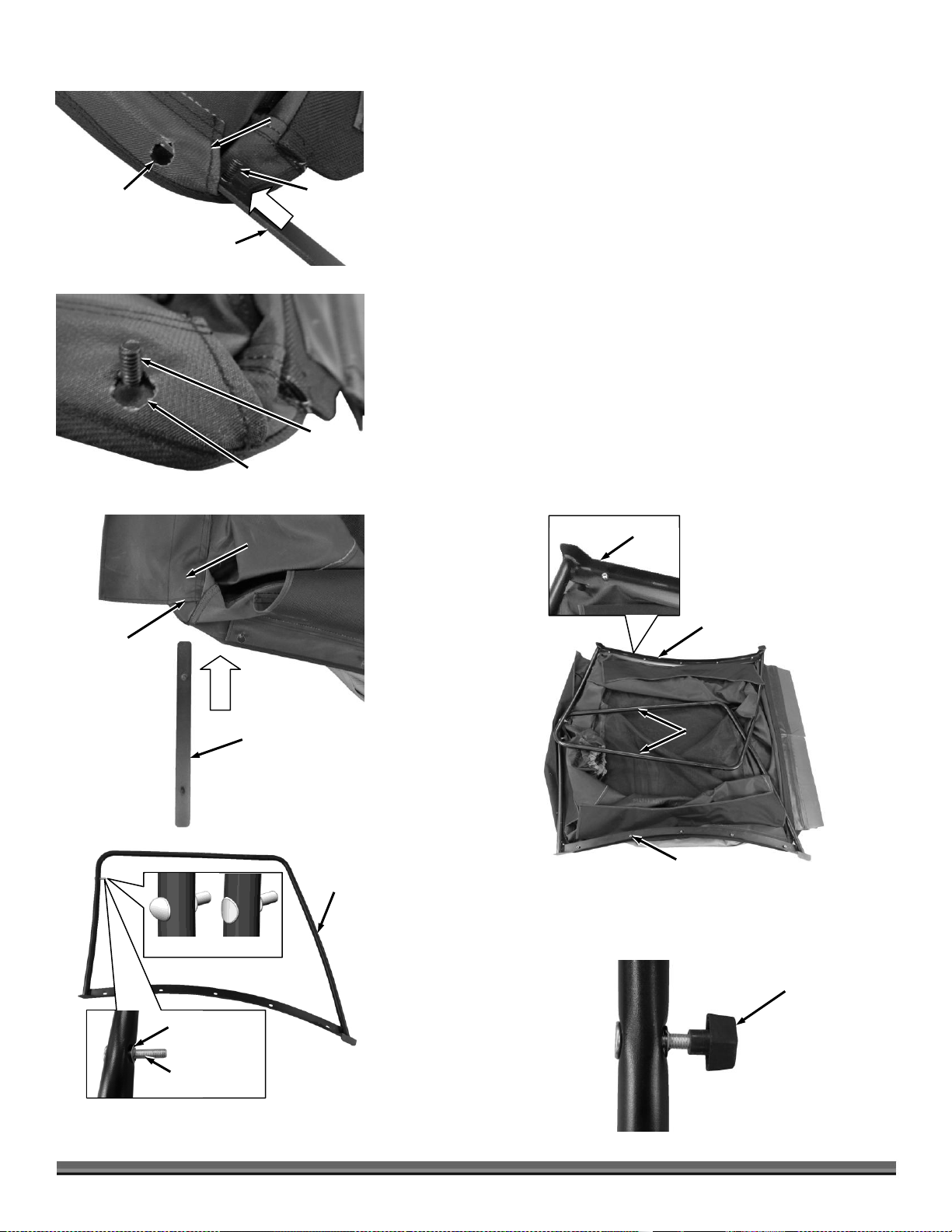
19. Position the Tube Frame Handle onto the two upper corner Bolts at the rear
and loosely secure with Knobs (Figure 38).
20. From the inside, insert 5/16-18 X 2.5" C-Head Bolts through the two lower
Tube holes, Fabric holes, and Tube Frame Handle. Loosely install Knobs on
each lower Bolt (Figure 38).
Note: Rack the Enclosure (move it side to side) as necessary to help get the
lower Bolts all the way through the handle. If this is very difficult and the Links
are tight such that they are bowing significantly then re-position the Link Bolt as
described in the next step. Make sure the Links are locked before returning to
this step.
21. Slide the Retainer to unlock the Links. If the Links were very tight in the
Enclosure such that they bowed significantly, move the Link Bolt and
Locknut to the alternate hole in the Link (Figure 39). Keep the Links
unlocked for the next step.
22. Position the Hinge with flanges facing out onto the front corner Bolts
(Figure 40). Loosely install Knobs onto the bolts.
Note: Install the Hinge over the two Bolts on one side, add those Knobs, and
then pull the Hinge over the two Bolts on the other side.
23. Position the Front Retainer studs through the Hinge and loosely install
Knobs (Figure 40).
24. Inside the Enclosure, place one end of the Top Tube Frame onto the Bolt
between the Side Tube Frame and Knob (Figure 41). Loosely tighten the
Knob.
25. Position the other end against the Side Tube above the Bolt and push the
Top Tube down as far as possible by hand. Step on the Top Tube to push
down until the threads snap into the slot (Figure 42). Tighten the two Knobs
against the Top Tube Frame Bracket.
26. Slide the Retainer to lock the Links (Figure 42).
16 DR
®
LEAF and LAWN
Page 17

27. Wrap the Enclosure Flap tightly around the Tube Frame Handle at the rear
Tube Frame
Handle
Figure 43
Enclosure
Flap
Velcro
Rear
Enclosure Sleeve
Figure 47
Outlet
Chute
Cable
Eyebolt
Hinge Pin
Figure 45
Hinge Holes
Cart
Eyebolt
Figure 44
Hole in Fabric
at the Front
Front
Top Tube Frame
Inside Enclosure
Knob
Figure 46
Hitch
Clip
and secure the Velcro Strips (Figure 43).
28. Insert the Eyebolt through hole in the Enclosure at the front and into the hole
in the Top Tube Frame (Figure 44). Secure with a Knob on the inside.
29. Tighten the 10 Retainer Stud Locknuts you installed in step 9 using a 7/16"
Wrench.
30. Fully tighten all Knobs. Make sure the Top Tube Knobs inside the Collector
are turned so they do not push into the Enclosure Fabric.
31. Turn the Enclosure over so it is right side up.
32. Close the Cart onto the Frame until the Dump Lever holds it down.
33. With the help of another person, place the Collector onto the Cart and align
the Hinge Halves (Figure 45).
34. Insert the Hinge Pin through the holes in the Hinges (Figure 45). The fit may
be tight for this initial setup. Use a hammer to tap the Pin in if necessary.
35. Insert Hitch Clips in the holes at the ends of the Pin to secure it (Figure 46).
36. Pull the Enclosure Sleeve around the Outlet Chute (Figure 47).
37. Attach the Cable Link to the Enclosure Eyebolt.
38. For Pro and Pro-XL: Pull the Dump Lever to raise the Cart and lift the Tube
Frame Handle at the rear to fully raise the Cart.
39. For Pro and Pro-XL: Install the left side Gas Spring as you did the right side
in step 2 of “Installing the Gas Springs”.
Note: There may be some Hardware left over that is not needed for your
application.
CONTACT US AT www.DRpower.com 17
Page 18

Setting up your Tractor
Hitch
Plate
Figure 48
Optional Hitch Plate Configurations
Deck
Adapter
Figure 49
Figure 50
Hitch Pin
Hitch Clip
Tow Hitch
Rubber
Washer
Always raise the Jack (if equipped) prior to towing this equipment. An
extended Jack can damage or deform the Jack or Frame if the Jack hits the
ground or an obstacle.
Hitch Plate Kit Installation (optional)
The DR Leaf and Lawn Vacuum requires a Pin Hitch hole on your Lawn Tractor.
DR Power Equipment offers several different Hitch Plate Kits if one is not
provided on your Tractor (Figure 48). Contact us at www.DRpower.com or call
one of our representatives at 1-800-DR-OWNER (376-9637) and they will be
happy to assist you.
Deck Adapter Installation
The DR Leaf and Lawn Vacuum requires a Deck Adapter on your Lawn Tractor
to route material to its 8" diameter hose.
A DR Power Equipment Universal Deck Adapter Kit (for right hand
discharge mowers) is available for you to fit to your machine if the
tractor manufacturer’s Deck Adapter is not available.
A DR Power Equipment Hose Adapter Kit is available to attach to
your non DR Power Equipment Deck Adapter to our 8" diameter Hose
if needed.
Contact us at www.DRpower.com or call one of our representatives at 1-800-DROWNER (376-9637) to order a Universal Deck Adapter Kit or Hose Adapter Kit.
1. Install the Deck Adapter onto your Lawn Tractor (Figure 49).
2. If you do not have a DR Deck Adapter and the 8" Hose will not fit your
Adapter, order a Kit from us using the contact info above. Install the Hose
Adapter Kit onto the end of your Deck Adapter as described in the Kit
instructions.
Connecting the DR Leaf and Lawn Vacuum to your Mower
1. Position the back Hitch Plate of your Mower near the Hitch of the Leaf and
Lawn Vacuum on level ground (Figure 50).
2. Operate the Jack (if equipped) to move the Frame up or down until the Tow
Hitch is aligned with the Tractor Hitch Plate.
3. Move the Leaf System into position on the Hitch Plate and install the Hitch
Pin with Rubber Washer and Hitch Clip to secure the Tow Hitch to the
Mower.
4. For models not equipped with a Jack, lift the Leaf System Hitch onto the
Hitch Plate as shown. For models equipped with a Jack, operate the jack
handle to raise the Hitch then move the Leaf System Hitch over the Lawn
Tractor Hitch Plate.
5. Install the Pin, Rubber Washer, and Hitch Clip as shown.
6. For models with a Jack, raise the Jack Wheel and install the Jack Safety Pin.
18 DR
®
LEAF and LAWN
Page 19

Connecting the Inlet Hose to the Deck Adapter
Figure 51
Deck
Adapter
Thumb Screw
Clamp
Inlet
Hose
Hose Cuff
Inlet Hose
Figure 52
Support and
Strap
Tractor Turned
Fully to the Left
Compress
Hose Ribs
Figure 53
Hose Clamp
Figure 54
Impeller
Housing
Inlet Hose
Make sure you do not shorten the Hose too much while following these
procedures. Follow the steps closely to ensure the machine is not damaged.
Tools Needed:
Wire Cutters
Knife
5/16" Wrench
1. Connect the Inlet Hose to the Deck Adapter by sliding the Hose Cuff over the
Hose Adapter (Figure 51).
Tip: Position the Thumb Screw Clamp toward the Mower so it will not make
contact with objects when mowing.
2. Tighten the Thumb Clamp tightly to secure the Hose to the Hose Adapter.
3. Turn the Tractor all the way to the left, while watching the Hose (Figure 52).
The Hose should not become too taut to twist or damage your Lawn Deck
Adapter.
4. Adjust the Rubber Strap on the Hose to keep the Hose off the Ground. If the
Strap cannot be positioned sufficiently on the Hose to prevent it from
kinking or dragging on the ground, reduce the length of the Hose as follows.
To Shorten the Hose (if needed)
NOTE: The Tractor must be turned fully to the left (Figure 52).
a. Compress the Hose Ribs together as much as you can without stretching
the Hose too much (Figure 53).
b. If more than 6 Ribs can be easily compressed, the Hose should be
shortened.
c. Loosen the Hose Clamp that secures the Inlet Hose to the Impeller
Housing with a 5/16" Wrench and pull the Hose from the Housing
(Figure 54).
CONTACT US AT www.DRpower.com 19
Page 20

Adding the Engine Oil and Gasoline
You must add oil before starting the engine. This machine is shipped without oil. Traces of oil may be in the reservoir from
factory testing, but you must add oil before starting the engine. Fill the reservoir slowly checking the dipstick frequently to
avoid overfilling.
To get an accurate reading when checking the oil level:
The machine should be on a level surface.
The dipstick should not be screwed down.
Wire Cutter Cut Point
(black Rib)
Knife Cut Line
(clear plastic)
Wire Cutters
Figure 55
Figure 56
Gas Fill
Dip Stick/
Oil Fill
d. Cut the Hose to the length required using Wire Cutters to cut the black
plastic spiral and then cut the clear Hose with the razor knife (Figure
55).
NOTE: Make sure you trace the area to cut around the Hose first to ensure you will
cut in the proper direction to end up on either side of the cut spiral.
e. Reinstall the Hose onto the Impeller Housing and tighten the Hose
Clamp. If the Tractor can be turned fully to the left, without the Hose
becoming too tight (with a slight amount of sag), the Hose is the
shortest length possible for your Tractor.
NOTE: Use only the recommended high detergent oil. Other types of oil could
cause problems operating your machine. Please refer to your Engine Owner’s Manual
for detailed oil information.
Tip: To avoid confusion, we recommend leaving the caps on the Fuel and
Engine oil Fills and only removing one cap each time when you are ready to pour
gasoline or oil into the correct Fill.
Refer to the Engine Users Manual for more detailed information on Engine
preparation procedures.
1. Place the machine on a level surface and add an initial quantity of the oil
recommended by the Engine Manufacturer (refer to your Engine Owner’s
Manual for recommended quantities), and wait one minute for the oil to settle
(Figure 56).
2. Check the Dipstick and continue adding a few ounces of oil at a time,
rechecking the Dipstick until the oil reaches the fill mark. Be careful not to
overfill.
3. Fill the gas tank to within 1-1/2 inches below top of fill neck (to allow for fuel
expansion) with fresh, unleaded gas. See your Engine Owner’s Manual for
more information.
20 DR
®
LEAF and LAWN
Page 21

Tire Pressure Check
Negative
Battery
Cable
Figure 58
Do not over inflate the tires. Inflate to the manufacturers recommended
pressure found on the tires.
Valve Stem
with Cap
Figure 57
Tools Needed:
Tire Pressure Gauge
Air Compressor
1. Remove the Valve Stem Protective Cap (Figure 57) and check the tire
pressure with a Tire Pressure Gauge.
2. Check what the manufacturers recommended pressure is that is stamped on
the side of the Tire.
3. If the pressure is too low, add air through the Valve Stem with an air hose.
4. Replace the Valve Stem Protective Cap when finished.
Connecting the Battery Wire (Electric-Starting Models Only)
We ship all Electric-Starting systems with the Negative Battery Terminal Wire
disconnected. This prevents the Battery from discharging during shipment.
Before using your DR LEAF and LAWN VACUUM, you must connect the Battery
Wire.
1. Connect the Negative Wire to the Negative Post on the Battery by sliding the
Terminal onto the Battery Post (Figure 58).
CONTACT US AT www.DRpower.com 21
Page 22

Chapter 3: Operating The DR LEAF AND LAWN VACUUM
Always refer to the Engine “Operator’s Manual” that came with your
machine for more detailed Engine operation procedures.
Choke
Lever
Fuel
Shutoff
Throttle Lever
Manual
Engine
Switch
Recoil
Starter
Grip
Key
Engine
Switch
Figure 59
Inspect the area where you will be working. The site must be free of
potentially hazardous obstacles such as stones, metal, or glass. Also, make
sure there won't be people or animals in the area around the DR Leaf and
Lawn Vacuum.
It may be helpful to better familiarize yourself with the features of your DR LEAF and LAWN VACUUM by reviewing Figure 1 in
Chapter 2 before beginning the steps outlined in this chapter.
Before Starting the Engine
NOTE: For Electric Start models, the Ignition Switch Keys are temporarily located
on the Switch Housing by means of a plastic Tie. Cut the Tie to remove the Keys for
use.
1. Connect the DR LEAF and LAWN VACUUM to your Lawn Tractor (see
previous chapter), remove the Safety Hitch Pin from the Jack (if equipped),
raise the Jack up and out of the way and replace the Safety Hitch Pin.
2. Check the Engine oil level every time you use the machine (refer to your Engine Operator’s Manual).
3. Check the Fuel level and make sure the Fuel Shut-Off Valve is in the OPEN position (refer to your Engine Operator’s Manual).
Starting and Stopping the Engine
1. When starting a cold Engine; push the Choke Control lever to the left (CHOKE) and the Throttle Control lever to the far right
(rabit position) (Figure 59). If re-starting a warm Engine, leave the Choke in the (RUN) position.
2. Manual Start - Grasp the Recoil Starter Handle and slowly pull until you feel resistance, then pull the cord with a smooth
accelerating motion to start the engine. One or two pulls usually starts the DR LEAF and LAWN VACUUM.
Electric Start - Turn the Key to START until the Engine starts and then release. The Key will snap back when released and the
Engine will continue to run.
3. After the Engine starts, slowly push the Choke Control lever back to the (RUN) position. Wait until the Engine runs smoothly
before each Choke adjustment. For best Engine performance, you should operate the Engine with the Throttle in the Fast
(Rabbit) position.
4. - To stop the Manual Start Engine, move the Throttle to the Slow (Turtle) position allowing the Engine to idle, and then turn
the Engine Switch to “OFF” position.
- To stop the Electric Start Engine, move the Throttle to the Slow (Turtle) position, and then turn OFF the Key.
22 DR
®
LEAF and LAWN
Page 23

Operating Safety
Enclosure Sleeve
Figure 62
Outlet
Chute
Cable Link
Eyebolt
Dump Lever
Figure 61
Figure 60
Hitch Pin
Hitch Clip
Tow Hitch
Rubber
Washer
Use common sense when using the machine. Learn to recognize the change in sounds when overloaded. Stop the engine
immediately if the machine becomes jammed to prevent damage to the machine.
If equipped, raise the Jack caster wheel as far as it will go and install the
locking pin prior to towing this equipment. An extended Jack caster
wheel can be damaged or deformed if it hits the ground or an object.
The DR Leaf and Lawn Vacuum is not equipped for highway use.
Never put your hands inside the vacuum hose while the engine is running. Always stop the engine and disconnect the spark
plug wire before clearing the vacuum hose.
Do not refuel the engine while it is hot or running.
Figure 63
Deck
Adapter
Thumb Screw
Clamp
Inlet
Hose
Hose Cuff
Towing the DR LEAF and LAWN VACUUM
1. Make sure you firmly attach the DR LEAF and LAWN VACUUM Hitch to your
Lawn Tractor using the Hitch Pin and Hitch Clip (Figure 60).
2. If equipped with a Jack, make sure the wheel is in the fully raised position
and the Jack Safety Pin is installed to lock it in place.
3. Make sure the Collector Cart is on the Frame so with the Dump Lever is
locked over the Latch on the Cart (Figure 61), the Collector Fabric Sleeve is
over the Chute (Figure 62), and the Inlet Hose Cuff is securely attached to
the Hose Adapter on your Tractor (Figure 63).
CONTACT US AT www.DRpower.com 23
Page 24

Towing Safety
Figure 64
15º Max.
Watch out for low branches, overhangs, and guy wires that may catch on top of the collector.
Never allow anyone to ride in or on the DR Leaf and Lawn Vacuum.
Obey local, state, and federal regulations when you tow the DR leaf and lawn vacuum across public roads and highways.
Use caution when backing up your lawn tractor or trying to make tight turns going forward with the DR Leaf and Lawn
Vacuum attached. Trying to turn too sharply can cause damage to the hitch and/or the lawn tractor if you hit an obstacle.
Go slowly in areas where tight turns are necessary. Straighten out the system before attempting to back up.
Do not use the DR Leaf and Lawn Vacuum on slopes greater than 15
degrees (Figure 64). Doing so could result in serious injury or damage to
your machine.
When operating the DR Leaf and Lawn Vacuum over uneven terrain and
slopes, use extreme caution to not tip over the machine. Move slowly,
especially with a full load, if the ground has ruts, bumps, and other
depressions.
On a slope, a heavy load will tend to shift. When using your DR Leaf and
Lawn Vacuum, keep in mind that loads tend to shift to the downhill side
of the collector enclosure. The higher and heavier the load, the greater
the chance you may tip over the machine.
Travel up and down slopes and avoid going across slopes. This is the
same recommendation for mowing with your lawn tractor alone.
Pick up stones, metal objects, glass, and sticks before vacuuming.
Slopes and Uneven Terrain
LEAF and LAWN VACUUM Tips
Note: Make sure the Engine is at full throttle when mowing and vacuuming leaves.
Tips:
Be careful in corners. Practice in first gear to understand the effects of the machine on your ability to turn sharply.
Drive your DR LEAF and LAWN VACUUM into the corner of your property and back out straight to mow as close to the
corner as possible. Do not go through ditches.
The Lawn Deck of your mower may tend to scatter some leaves in front and to the right of the Lawn Deck. Keeping the
discharge side toward the remaining leaves will simplify cleanup by avoiding blowing leaves back onto the areas that
you already finished. When you need to vacuum with the discharge side toward the completed area of the lawn, overlap
24 DR
the discharge side of the Lawn Deck at least a foot over the already completed section of the lawn.
To prevent clogging the Deck Adapter, mow grass that is dry and not more 2" at a time. To keep your grass healthy, we
recommend cutting less than 1/3 the grass height.
Run your Lawn Deck with your Tractor at full throttle all the time to maximize the lift from your Lawn Deck and assist
your DR LEAF and LAWN VACUUM system.
Avoid dragging the Hose over curbs, stonewalls, or piles of cut branches. The Hose is tough, but can puncture on
sharp objects. This could also crack the Mower Deck Adapter.
®
LEAF and LAWN
Page 25

Cut wet grass can be very heavy. Fill the Collector only 3/4 full if the
Rear Flaps
Figure 67
Always shut off the tractor engine and the vacuum engine and use caution
when dumping the collector load.
Never back up with the Cart in the dump position.
Dump
Lever
Figure 65
Unlock
Collector
Lock Collector
Latch
Tube Frame
Handle
Figure 66
Never drive in reverse with the Collector in the dump position.
Empty the Collector after each use. Do not store the Leaf System with debris
in the Collector.
Enclosure
Sleeve
Figure 69
Outlet
Chute
Dump
Lever
Pull Down Here
Figure 68
material is very wet. That will make the Leaf System easier to pull and
to dump.
Dumping
1. Shut down the Mower and Vacuum Engines and set the Mower Parking Brake
when you are at the Dump area.
2. Pull the Dump Lever to tip the Collector back (Figure 65). If the Collector
doesn’t tip back on its own you can lift up on the front of the Cart.
3. Lift up on the Tube Frame Handle to start emptying the Container and then
release (Figure 66). The Upper Collector will remain raised (Figure 67).
4. Drive the Mower forward with the Collector fully open to move the Leaf
System away from the pile of debris and allow all debris to slide from the Cart
Bed.
5. Pull down on the Tube Frame Handle to close the Enclosure onto the Cart.
Ensure that the Rear Flaps are positioned inside the Enclosure (Figure 67).
6. Pull down at the front of the Enclosure until the Latch is secured by the Dump
Lever (Figure 68).
7. Pull the Enclosure Sleeve around the Outlet Chute (Figure 69).
CONTACT US AT www.DRpower.com 25
Page 26

Converting to Cart Trailer Mode
Hinge Pin
Figure 74
Hitch Clip
Enclosure
Before performing any maintenance, repairs or inspection, you must first shut
off the mower and leaf and lawn vacuum engines, wait five minutes for all
parts to stop and cool, and disconnect the spark plug wire of the leaf and lawn
vacuum.
Hose Clamp
Figure 71
Impeller
Housing
Inlet Hose
Figure 72
Deck
Adapter
Thumb Screw
Clamp
Inlet
Hose
Hose Cuff
Hose
Figure 70
Rubber Strap
Hose Support
Enclosure
Sleeve
Figure 73
Outlet
Chute
Cable Link
Tools Needed:
5/16" Wrench
Two 3/4" Wrenches
Flat Head Screwdriver
Safety Glasses
1. Remove the Rubber Bungee from the Hose Support (Figure 70).
2. Disconnect the Hose from the Impeller Housing using a 5/16" Wrench
(Figure 71).
3. Turn the Thumb Screw Clamp to disconnect the Hose from the Deck
Adapter (Figure 72).
4. Unhitch the Cable Link from the Enclosure (Figure 73).
5. Pull the Enclosure Sleeve from the Outlet Chute.
6. Remove the Hitch Clip from one end of the Hinge Pin and from the other
end pull the Hinge Pin from the Cart/Enclosure Hinge (Figure 74).
7. Lift the Enclosure from the Cart and set aside. For larger models this is a
good time to have a helper.
26 DR
®
LEAF and LAWN
Page 27

8. Pull the Dump Lever out to raise the Cart Bed (Figure 75).
Figure 77
Clevis Pins and
Hitch Clips
Bolts and
Locknuts
Figure 78
Gas Spring
Figure 76
Screwdriver
Retaining Clip
Dump
Lever
Figure 75
Unlock
Cart
Lock Cart
Latch
Note: The Gas Spring makes it easier to dump the loads in the Collector. The
Premier unit has one Gas Spring and can be left as is for Cart Mode. The
Pro and Pro XL use two Gas Springs and the left hand Spring should be
removed so closing the Cart is easier in Cart mode.
9. Pull out on one end of the left side Gas Spring to apply pressure (Figure 76).
Use a Flat Head Screwdriver to pry under the Retaining Clip just enough so
the Gas Spring end can be removed. Repeat for the other end of the Spring.
10. Leave the Cart tilted up for the next step.
11. Remove the two sets of Bolts and Locknuts from the Frame using two 3/4"
Wrenches (Figure 77).
12. If your machine has a Jack you should rotate the Handle to bring the Jack
Wheel up as high as it will go. This moves the Tow Hitch closer to the
ground to make disconnecting the Power Unit easier.
13. Block the Cart Wheels and have a helper pull on the Outlet Duct to take
pressure off the Pins when you perform the next step (Figure 78).
14. Remove the front (closest to the Hitch) Hitch Clip and Clevis Pin from the
Power Unit Frame (Figure 77).
15. Remove the rear Hitch Clip and Clevis Pin from the Power Unit Frame
16. Move the Hitch Pin, Rubber Washer, and Hitch Clip from the Power Unit
Hitch to the Pin Hole of the Cart frame to hitch the Cart to your Tractor.
17. Lift up on the Hitch to roll the Power Unit out of the way. Store the Power
Unit, Enclosure, Hose and Support in a protected dry area.
18. Push down at the front of the Cart until the Latch is secured by the Dump
Lever.
CONTACT US AT www.DRpower.com 27
Page 28

Tube Frame
Handle
Figure 82
Rear
Threaded
Knobs
Threaded
Knobs
19. Hitch the Tow Bar of the Cart to your Tractor using the Hitch Pin with
Figure 79
Hitch Pin
Hitch Clip
Tow Bar
Rubber
Washer
Never allow anyone to ride in the Cart.
Do not tow on slopes greater than 15 degrees.
Travel up and down slopes and avoid going across slopes. This is the
same recommendation for using your lawn tractor alone.
Never backup with the Cart in the dump position.
Hinge
Figure 80
Knobs
Tube Frame
Handle
Figure 81
Enclosure
Flap
Velcro
Rear
Top Tube
Frame
Figure 83
Threaded
Knob
Rubber Washer and secure using the Hitch Clip (Figure 79).
As you fill the Cart, distribute the load fairly evenly.
Do not overfill the Cart.
Drive slower when turning corners and on bumpy terrain so the load does
not shift or fall out.
Gravel, stone, and sand are very heavy. Never fill the Cart to the top with
these items as they would exceed the weight limits.
Collapsing the Upper Collector for Compact Storage
The Upper Collector can be stored fully assembled, but can also be collapsed for
more compact storage.
1. Remove the Knobs from the Hinge and lift off the Hinge (Figure 80).
Reinstall the Knobs so they are not lost.
2. Unlatch the Velcro from around the Handle (Figure 81). Remove the Knobs
from the Handle and lift the Handle off (Figure 82). Reinstall the Knobs so
they are not lost.
3. Remove the Knobs from the Top Tube Frame and pull off the Top Tube
Frame (Figure 83). Reinstall the Knobs so they are not lost.
28 DR
®
LEAF and LAWN
Page 29

4. Slide the Retainer on the Link and scissor the Links partially closed (Figure
Figure 84
2
1
Retainer
Link
Collector
Figure 85
84).
5. Prop the Upper Collector upright then standing to the side pull the front and
back Enclosure fabric (Figure 85).
6. Fully collapse by pulling the sides together. Lift and store. Also store the
Hinge, Handle, and Top Tube Frame with the Enclosure.
CONTACT US AT www.DRpower.com 29
Page 30

Chapter 4: Maintaining The DR LEAF and LAWN VACUUM
PROCEDURE
BEFORE EACH
USE
AFTER EACH
USE
EVERY 25
HOURS
EVERY 100
HOURS
Check Engine Oil Level
Check General Equipment Condition, e.g. tight
nuts, bolts, welds, etc.
Check Tire Pressure
Check Hose for wear, holes, or abraded areas.
Clean Engine Exterior & Cooling Fins
Empty the Collector
Check Battery Charge
Clean Engine Air Filters
Change Engine Oil
1st time 5
Check Exterior of Impeller Housing for Wear
Lubricate Wheel Bearings
Replace Spark Plug
Replace Engine Air Filters
Before performing any maintenance, repairs or inspection, you must first shut off the mower and leaf and lawn vacuum engines,
wait five minutes for all parts to stop and cool, and disconnect the spark plug wire of the leaf and lawn vacuum.
Before performing any maintenance, repairs or inspection, you must first shut off the mower and leaf and lawn vacuum engines,
wait five minutes for all parts to stop and cool, and disconnect the spark plug wire of the leaf and lawn vacuum.
Grease Fitting
Figure 86
Regular maintenance is the way to ensure the best performance and long life of your machine. Please refer to this manual and the
engine manufacturer's owner's manual for maintenance procedures. Service intervals listed in the checklist below supersede
those listed in the engine manufacturer's owner's manual.
Regular Maintenance Checklist
Lubrication
Your DR LEAF and LAWN VACUUM was lubricated at the Factory. The operator needs to provide Engine lubrication and lubricate
the Wheels periodically.
Tools and Supplies Needed:
Grease gun with Multipurpose Automotive Grease
Clean Rags
LUBRICATE WHEEL BEARINGS:
1. Clean the Grease Fitting with a clean Rag (Figure 86).
2. Lubricate each Wheel with Multipurpose Automotive Grease using a grease
gun on the Grease Fitting.
30 DR
®
LEAF and LAWN
Page 31

REMOVING AND REPLACING THE ENGINE OIL
Figure 87
Washer
Cotter Pin
Before performing any maintenance, repairs or inspection, you must first shut off the mower and leaf and lawn vacuum engines,
wait five minutes for all parts to stop and cool, and disconnect the spark plug wire of the leaf and lawn vacuum.
Impeller
Tool
Figure 88
Impeller
Refer to the Engine Operator Manual for Engine Procedures for removing and replacing the oil.
NOTE: Be sure to use environmentally safe disposal procedures in the disposing of the used oil.
Replacing the Wheels
Tools Needed:
Locking Pliers or Needle Nose Pliers.
Jack and Stand
1. Jack up the Frame and support it with Blocks or a Jack Stand so the Wheel is
off the ground.
2. Remove the Cotter Pin with Locking Pliers or Needle Nose Pliers (Figure 87).
3. Remove the Large Washer and Wheel.
4. Install the new Wheel.
5. Install the Large Washer and secure with the Cotter Pin (bend the ends of
the Cotter Pin to lock it onto the Axle.
Impeller Maintenance
An Impeller Tool is provided in case you ever need to remove the Impeller for
service. Simply remove the Bolt and Washer holding the Impeller onto the
Engine Shaft and thread the Impeller Tool into the Impeller until it releases
from the Engine (Figure 88).
CONTACT US AT www.DRpower.com 31
Page 32

Battery Care (For Electric-Starting Models Only)
When you are finished charging the battery, disconnect the charger from the outlet first, then disconnect the battery charger wires
from the battery. If you leave the battery charger wires connected to the battery, the battery will discharge itself back into the
charger.
Before performing any maintenance, repairs or inspection, you must first shut off the mower and leaf and lawn vacuum engines,
wait five minutes for all parts to stop and cool, and disconnect the spark plug wire of the leaf and lawn vacuum.
Proper care can extend the life of a Battery. Follow these recommendations to ensure your Battery’s best performance and long
life:
Do not allow the Battery charge to get too low. If the machine is not used, charge the Battery every 4 – 6 weeks. Operate the
engine for at least 45 minutes to maintain proper Battery charge.
Store an unused Battery in a dry area that does not freeze.
Do not charge an already charged Battery. In theory, you cannot overcharge our Battery with a trickle charger; however, when a
Battery is fully charged and the charger is still on, it generates heat that could be harmful to the Battery. A fully char ged Battery
will read 12V-13.2V with a voltmeter.
Do not continue to crank your Engine when the Battery charge is low.
Charging the Battery
Operate the vacuum Engine for at least 45 minutes to maintain proper Battery charge. If the Battery loses its charge, you will need
to use a trickle charger (like the DR Battery Charger) to recharge it. The Charger should have an output of 12 volts at no m ore
than 2 amps.
At 1 amp the Battery may need to be charged for as long as 48 hours.
At 2 amps, the Battery may need to be charged for as long as 24 hours.
NOTE: Using the Recoil Starter and then running the Engine will not recharge a dead or significantly discharged Battery.
To connect a Battery Charger to your DR LEAF and LAWN VACUUM, follow the steps listed below.
1. Attach the Black (-) alligator clipped wire from the Charger Adapter to the Negative (-) terminal of the Battery, then attach the
Red (+) alligator clipped wire to the Positive (+) Battery terminal.
2. Plug the Charger into a standard wall outlet.
Typically, the Battery takes between 6 and 8 hours to fully charge. The Battery does not have a “memory”; so don’t
worry about overcharging the Battery or charging it too often.
You can charge the Battery many times. The Battery lasts longer if you charge it before it is fully drained. Keep it fully
charged and at room temperature when not using your DR LEAF and LAWN VACUUM.
If the Battery does not hold its charge for very long under normal conditions or it simply won’t hold a charge, then
replace it. You can purchase replacement Batteries directly from us. To install your new Battery, follow the directions
below.
32 DR
®
LEAF and LAWN
Page 33

Replacing the Battery
Clamp
Figure 89
Terminals
Bolt and Locknut
Cable Tie
Tools Needed:
Two 7/16" Wrenches
Wire Cutters
1. Disconnect the Battery Terminals (Figure 89).
2. Cut the Cable Tie that securing the Wires to the Clamp using Wire Cutters.
3. Remove the Bolts and Locknuts that secure the Battery Clamp using two
7/16" Wrenches.
4. Remove the Clamp and the dead Battery.
5. Install the new Battery.
6. Install the Battery Clamp and secure with the Bolts and Locknuts using two
7/16" Wrenches.
7. Attach the Battery Terminals. Green Wire to negative black Terminal and
Red Wire to positive red Terminal.
Disposing of the Battery Responsibly (Electric-Start Models)
The Battery is a sealed lead-acid Battery. Recycle or dispose of it in an environmentally sound way.
Do not dispose of a lead-acid Battery in a fire; the Battery may explode or leak.
Do not dispose of a lead-acid Battery in your regular, household trash. Law in most areas prohibits incinerating, disposing in a
landfill, or mixing a sealed lead-acid Battery with household trash.
Recycling a Used Battery
Please dispose of your used Batteries responsibly by recycling them. Call your local Solid Waste Management District or your
local waste handler to locate the collection site nearest you. Some collection sites recycle Batteries year-round; others collect
them periodically.
You can also visit the Web site of Earth 911 for more information [www.earth911.org]. Once there, in the appropriate box, type in
what it is you are recycling and also type your zip code. The site will provide a list of recycling centers located near you.
For a fee, you can recycle your Batteries with the International Metals Reclamation Company. Visit them at www.inmetco.com and
click Services; or contact them at:
INMETCO
PO Box 720
245 Portersville Road
Ellwood City, PA 16117
(724) 758-2825; fax (724) 758-2845
To learn more about hazardous waste recycling, visit the Web site for Battery Council International [www.batterycouncil.org] or for
the Environmental Protection Agency [www.epa.gov].
CONTACT US AT www.DRpower.com 33
Page 34

Chapter 5: Troubleshooting
SYMPTOM
POSSIBLE CAUSE
Engine recoil will not
pull out or is difficult to
pull.
Check the Engine oil level, the Engine may be seized. See your engine owners manual.
There may be an oil compression lock in the cylinder. Take out the Spark Plug; hold a rag over
the Spark Plug hole and pull the Recoil Cord several times to blow out any oil in the cylinder.
Wipe off the Spark Plug and reinstall it.
The Recoil may be broken or jammed. Visit us at www.DRpower.com or call 1-800-DR-OWNER
(376-9637) for assistance.
The Engine won’t start
manually.
(Please refer to the
Engine Owner’s Manual
for engine-specific
procedures.)
Check that the Spark Plug Wire is attached.
Check the oil and gas level. See your engine owners manual.
You should be using fresh, clean gas. If the gas is old, change it. Use a fuel stabilizer if you keep
gas longer than one month.
Check the Throttle adjustment and travel. See your engine owners manual.
The Spark Plug should be clean. If the Spark Plug is dirty or cracked, change it. If it’s oily, leave
it out, hold a rag over the Plug hole and pull the Recoil Cord several times to blow out any oil in
the cylinder, then wipe off the Plug and reinstall it.
If the Engine still won’t start, visit us at www.DRpower.com or call 1-800-DR-OWNER (376-9637)
for assistance.
The Engine won’t start
using Electric-Start.
(Please refer to the
Engine Owner’s Manual
for engine-specific
procedures.)
Check the previous section (Manual Starting) for possible causes.
Check the wire connections—especially the ground connection, the green wire coming from the
Battery, where it connects to the Engine.
The Battery should be charged. Check the voltage yourself or at a gas station. If it’s low, charge
it with a 12-volt, 1 to 2 Amp trickle charger. If you don’t use your machine for at least 45 minutes
at a time, the Battery may need to be periodically charged. See the Battery Care section in
Chapter 4.
If your Battery is charged and your DR still won’t start, visit us at www.DRpower.com or call 1-
800-DR-OWNER (376-9637) for assistance.
Engine smokes.
Check the oil level and adjust as needed.
You may be operating the machine on too great an incline. See Slopes on page 25.
Check the Air Filter and clean or replace if needed.
You may be using the wrong oil—too light for the temperature. Refer to your Engine Owner’s
Manual for detailed information.
Clean the Engine cooling fins and the carburetor housing if they are dirty.
If the Engine still smokes, visit us at www.DRpower.com or call 1-800-DR-OWNER (376-9637) for
assistance.
Before performing any maintenance, repairs or inspection, you must first shut off the Mower and Leaf and Lawn Vacuum engines,
wait five minutes for all parts to stop and cool, and disconnect the Spark Plug Wire of the Leaf and Lawn Vacuum.
Most problems are easy to fix. Consult the Troubleshooting Table below for common problems and their solutions. If you
continue to experience problems, contact us at www.DRpower.com or call toll-free 1-800-DR-OWNER (376-9637) for support.
Troubleshooting Table
34 DR
®
LEAF and LAWN
Page 35

Troubleshooting Table (Continued)
SYMPTOM
POSSIBLE CAUSE
The Engine lacks power
or is not running
smoothly.
(Please refer to the
Engine Owner’s Manual
for engine-specific
procedures.)
Check the Throttle travel. See your engine owners manual.
The Choke should be pushed all the way to the right (RUN). See your engine owners manual.
Check to see if the Air Filter is clean. If it’s dirty, change it following the procedure in the Engine
Owner’s Manual.
The Spark Plug should be clean. If the Spark Plug is dirty or cracked, change it. If it’s oily, leave
it out, hold a rag over the Plug hole and pull the Recoil Cord several times to blow out any oil in
the cylinder, then wipe off the Plug and reinsert it.
You should be using fresh, clean gas. If the gas is old, change it. Use a fuel stabilizer if you keep
gas longer than one month.
Check and make sure the Engine has the right amount of clean oil. If it’s dirty, change it
following the procedure in your engine owners manual.
If your Engine still lacks power, visit us at www.DRpower.com or call 1-800-DR-OWNER (376-
9637) for assistance.
Wheels tracking left or
right while being towed.
Check the tire pressure. Refer to the Tire manufacturers recommended pressure on the side of
the Tire and adjust pressure as needed.
Lawn Deck is not
vacuuming well.
Be sure the Leaf and Lawn Vacuum Engine is running at full throttle.
Be sure the Lawn Deck Blades are engaged and running at full throttle.
Be sure the Deck is set at the proper mowing height.
Use 1st or 2nd gear on your Lawn Tractor for best results.
Turn off the Lawn Tractor Engine and Vacuum Engine, and check the Deck Adapter for clogs.
Look for clogs along the Hose. Shake the Hose to loosen and free any clog.
Turn off the Lawn Tractor Engine and Leaf and Lawn Vacuum Engine, and disconnect the Leaf
and Lawn Vacuum Engine Spark Plug Wire. Check for clogs in the Outlet Duct and Inlet Hose.
If your Lawn Deck still is not vacuuming properly, visit us at www.DRpower.com or call 1-800-
DR-OWNER (376-9637) for assistance.
Leaves or grass come
out of the back of the
Enclosure.
Check that the rear Flaps are tucked in to the Enclosure.
Leaves or grass come
out where the Outlet
Chute and Enclosure
meet.
Be sure the Enclosure Sleeve is fully installed around the Outlet Duct.
Try to rock the Impeller Housing toward and away from the Enclosure. If it is loose then you will
need to tighten the Bolts located behind the Impeller.
The Collector does not
fully latch
Pull the Collector down fairly rapidly against the latch. If the latch does not return fully, move it
closed manually, loosen the bolt going through the latch pin and retighten the bolt.
Before performing any maintenance, repairs or inspection, you must first shut off the mower and leaf and lawn vacuum engines,
wait five minutes for all parts to stop and cool, and disconnect the spark plug wire of the leaf and lawn vacuum.
CONTACT US AT www.DRpower.com 35
Page 36

Chapter 6: Parts Lists and Schematic Diagrams
Parts List – FRAME AND CART ASSEMBLY
NOTE: Part numbers listed are available through DR Power Equipment.
Ref# Part# Description
1 33799 Frame, Rear
2 18737 Pin, Clevis, 1/2" OD X 4.5" LG
3 16003 Pin, Hair, 1/2" to 9/16", .12" Wire
4 34241 Support, Pivot, Cart Bed, PREMIER
34257 Support, Pivot, Cart Bed, PRO & XL
5 35439 Cart Bed W/Labels, PREMIER
35440 Cart Bed W/Labels, PRO & XL
6 35034 Bolt, Carr, 5/16-18 X 3", GR5, ZP
7 35033 Bolt, Carr, 5/16-18 X 1.75", GR5, ZP
8 33332 Nut, Nylon Lock, Flanged, 5/16-18
9 34242 Support, Cart Bed
10 11076 Nut, Nylon Lock, 5/16-18, ZP
11 33804 Washer, .344" ID X .88" OD X .12"
12 33805 Spacer, .327" ID X .51" OD X 2.69"
13 18980 Bolt, HCS, 5/16-18 X 4.50", GR2, ZP
14 33793 Gas Spring, 500-300 mm, 150 Lb
Ref# Part# Description
15 33798 Stud, Ball, 10 mm
16 35443 Handle W/Grip & Label, Latch
17 11024 Grip, Latch Handle
18 33803 Spring, C, .545" ID X .055" Wire X 2.2"
Long
19 11148 Bolt, HCS, 1/4-20 X 1.75", GR5, ZP
20 11073 Nut, Nylon Lock, 1/4-20, ZP
21 33802 Bracket, Axle
22 34256 Axle,, PRO & XL
33801 Axle, PREMIER
23 12334 Bolt, HCS, 3/8-16 X 1.75", GR5, ZP
24 33333 Nut, Nylon Lock, Flanged, 3/8-16
25 33794 Wheel & Tire, 14 X 5.3/4.50-8
26 18064 Washer, .8" ID, 1.5" OD X .11"
27 12685 Pin, Cotter, 3/16" X 1.5"
28 34279 Label, Operating
29 34140 Label, DR Logo, 4" Silver
36 DR
®
LEAF and LAWN
Page 37

Schematic – FRAME AND CART ASSEMBLY
CONTACT US AT www.DRpower.com 37
Page 38

Parts List – POWER UNIT ASSEMBLY
NOTE: Part numbers listed are available through DR Power Equipment.
Ref# Part# Description
1 33800 Frame, Front
2 33799 Frame, Rear
3 26556 Bolt, HCS, 1/2-13 X 2.75", GR5, ZP
4 33335 Nut, Nylon Lock, Flanged, 1/2-13
5 21154 Pin, Clevis, 1/2" OD X 3.5" LG
6 16003 Pin, Hair, 1/2" to 9/16"
7 18737 Pin, Clevis, 1/2" OD X 4.5" LG
8 18967 Washer, Neoprene, .49" Id X 1.06" OD
9 34249 Leg, Engine Support
10 34250 Leg, Engine Support, Short
11 11468 Bolt, HHCS, 1/4-20 X 2.0", GR2, ZP
12 11073 Nut, Nylon Lock, 1/4-20, ZP
13 34277 Wheel, 4"
14 23499 Washer, SAE Flat, 1/2", ZP
15 23500 Pin, Cotter, 7/64" X 1", ZP
16 34269 Jack, Trailer
17 11152 Bolt, HCS, .3/8-16 X 1", GR5, ZP
18 33333 Nut, Nylon Lock, Flanged, 3/8-16
19 13447 Battery, 12V, Ah
20 24230 Strap, Battery
21 11983 Bolt, HCS, 1/4-20 X 3/4", GR2, ZP
22 35434 Engine W/Label, DR 9.59 TQ, E/S,
50st/CE
35436 Engine W/Label, DR 13.28 TQ, E/S,
50st/CE
35438 Engine W/Label, DR 16.96 TQ, E/S,
50st/CE
35433 Engine W/Label, DR 9.59 TQ, M/S,
50st/CE
35435 Engine W/Label, DR 13.28 TQ, M/S,
50st/CE
35437 Engine W/Label, DR 16.96 TQ, M/S,
50st/CE
23 13443 Bolt, HCS, 5/16-18 X 1-1/2, GR5, ZP
(PREMIER)
11985 Bolt, HCS, 3/8-16 X 1.5", GR5, ZP (PRO
& XL)
24 33332 Nut, Nylon Lock, Flanged, 5/16-18
(PREMIER)
33333 Nut, Nylon Lock, Flanged, 3/8-16 (PRO
& XL)
25 15045 Bolt, HCS, 5/16-18 X 1-3/4", GR5, ZP
(PREMIER E/S)
12334 Bolt, HCS, 3/8-16 X 1.75", GR5, ZP (PRO
& XL E/S)
38 DR
®
LEAF and LAWN
Ref# Part# Description
26 11250 Washer, Lock, 5/16", Ext Tooth
(PREMIER E/S)
35040 Washer, Lock, 3/8", Ext Tooth (PRO &
XL E/S)
27 11069 Nut, Hex, 5/16-18, GR2, ZP (PREMIER
E/S)
12383 Nut, Hex, 3/8-16, ZP (PRO & XL E/S)
28 34275 Wire, Battery Ground
29 34276 Wire, Battery Positive
30 11214 Cable Tie, 7-1/2" Long
31 29487 Boot, Rubber
32 34235 Housing, Impeller, Engine Side
33 34240 Spacer, Impeller, PREMIER
34239 Spacer, Impeller, PRO & XL
34 35031 Bolt, HCS, 5/16-24 X 3.0", GR8, YZP
(PREMIER)
35041 Bolt, HCS, 5/16-24 X 2.75", ZP (PRO &
XL)
35 35032 Washer, Lock, 5/16", GR8 Split, ZP
36 34236 Impeller
37 35035 Bolt, HCS, 5/16-24 X 2.5", GR8, YZP
38 11076 Nut, Nylon Lock, 5/16-18, ZP
39 35036 Washer, Flat, .344" X 1.25" X .25", ZP
40 35441 Housing W/Label, Impeller
41 34278 Label, Warning, Chute & Hose
42 34238 Liner, Housing, Impeller
43 14451 Bolt, Carr, 10-24 X .62", ZP
44 35038 Nut, Nylon Lock, Flange, 10-24, ZP
45 35023 Bolt, Hex, Flange, 5/16-18 X .75"
46 35024 Bolt, HCS, 5/16-18 X 1.25", GR5, ZP
47 34243 Bracket, Rod, Hose
48 18755 Nut, Nylon Lock, 5/16-18, LP
49 34244 Rod, Support, Hose
50 34245 Chute, Impeller Outlet, PREMIER
34246 Chute, Impeller Outlet, PRO & XL
51 11241 Washer, Flat, 5/16", USS, ZP
52 11243 Washer, Lock, Split, 5/16"
Page 39

Schematic – POWER UNIT ASSEMBLY
CONTACT US AT www.DRpower.com 39
Page 40

Parts List – COLLECTOR ASSEMBLY
NOTE: Part numbers listed are available through DR Power Equipment.
Ref# Part# Description
1 33792 Enclosure, Fabric, PREMIER
34268 Enclosure, Fabric, PRO & XL
3 33777 Tube Frame, Collector, RH, PREMIER
34259 Tube Frame, Collector, RH, PRO & XL
4 33778 Tube Frame, Collector, LH, PREMIER
34260 Tube Frame, Collector, LH, PRO & XL
5 33789 Retainer, Enclosure, RH
6 33790 Retainer, Enclosure, LH
7 11073 Nut, Nylon Lock, 1/4-20, ZP
8 33791 Retainer, Enclosure, Front
9 35030 Knob, 5/16-18, W/Lock, 1.16" X .93"
10 33780 Hinge, Tube Frame, PREMIER
34251 Hinge, Tube Frame, PRO & XL
11 35027 Bolt, C-Head, 5/16-18 X 1.75", ZP
12 27905 Push Nut, 5/16"
13 33781 Tube Frame, Collector, Top
Ref# Part# Description
14 35028 Eyebolt, 5/16-18 X 2", Forged, ZP
15 33443 Link, Chain, Threaded Connector
16 34273 Cable, Collector, PREMIER
34274 Cable, Collector, PRO & XL
17 33782 Link, Flat, Collector, PREMIER
34253 Link, Flat, Collector, PRO & XL
18 33783 Link, Offset, Collector, PREMIER
34254 Link, Offset, Collector, PRO & XL
19 35023 Bolt, Hex, Flange, 5/16-18 X .75"
20 11241 Washer, Flat, 5/16", USS, ZP
21 11076 Nut, Nylon Lock, 5/16-18, ZP
22 33784 Retainer, Spring, Link
23 33779 Handle, Tube Frame
24 35026 Bolt, C-Head, 5/16-18 X 2.5", ZP
25 35439 Cart Bed W/Labels, PREMIER
35440 Cart Bed W/Labels, PRO & XL
26 33786 Pin, Hinge
27 33787 Pin, Cotter, Hair, 1/4-3/8
40 DR
®
LEAF and LAWN
Page 41

Schematic – COLLECTOR ASSEMBLY
CONTACT US AT www.DRpower.com 41
Page 42

Parts List and Schematic – HOSE ASSEMBLY
NOTE: Part numbers listed are available through DR Power Equipment.
Ref# Part# Description
1 35441 Housing W/ Label, Impeller
2 33795 Hose, 8" ID X 72" Long, PVC
3 34248 Cuff, Hose, 8"
4 33796 Clamp, Hose, 8", Bridge
5 33797 Clamp, Hose, 8", Thumbscrew
6 35442 Strap & Hook Set
42 DR
®
LEAF and LAWN VACUUM
Page 43

Notes:
CONTACT US AT www.DRpower.com 43
Page 44

Before performing any maintenance, repairs or inspection, you must first shut off the mower and leaf and lawn vacuum engines,
wait five minutes for all parts to stop and cool, and disconnect the spark plug wire of the leaf and lawn vacuum.
Before performing any maintenance, repairs or inspection, you must first shut off the mower and leaf and lawn vacuum engines,
wait five minutes for all parts to stop and cool, and disconnect the spark plug wire of the leaf and lawn vacuum.
Daily Checklist for the DR LEAF and LAWN VACUUM
To help maintain your DR LEAF and LAWN VACUUM for optimum performance, we recommend you follow this checklist
each time you use your Vacuum.
[ ] OIL: With the machine on a level surface, remove the Oil Fill Cap and check the oil level. Fill the reservoir according to
the Dipstick with the recommended motor oil.
[ ] GAS: Fill the gas tank with fresh, unleaded gasoline.
[ ] ENGINE: It is very important to keep the Engine clean. Remove dirt and other debris from the Engine cooling fins and
debris guard. A dirty Engine retains heat and can cause damage to internal Engine components.
[ ] HARDWARE: Check all nuts and bolts to be sure that the components are secure.
[ ] FRAME: Check all welds to be sure that the frame is intact and secure.
[ ] HOSES: Inspect the Hose for holes, frayed, worn, kinked, or abraded areas. Replace a damaged or worn Hose.
[ ] COLLECTOR: Empty the Collector after each use. Do not store the Leaf System with debris in the Collector.
End of Season and Storage
NOTE: Please refer to the Engine Owner’s Manual for engine-specific procedures.
Change the oil. Refer to your Engine Owner’s Manual for detailed information.
If your DR LEAF and LAWN VACUUM will be idle for more than 30 days, we recommend using a gas stabilizer. This will
prevent sediment from gumming up the carburetor. If there is dirt or moisture in the gas or tank, remove it by draining the
tank. Completely fill the tank with fresh, unleaded gas and add the appropriate amount of stabilizer or gasoline additive.
Run the engine for a short time to allow the additive to circulate.
Remove the spark plug and pour about 1 ounce of motor oil into the cylinder hole. Replace the plug and pull the recoil
starter rope until you feel strong resistance. This will coat the piston and seat the valves to prevent moisture buildup.
Clean or replace the air filter. Refer to your Engine Owner’s Manual for detailed information.
Clean dirt and debris from the cylinder head cooling fins, Impeller housing, debris screen, and muffler area of the engine.
Clean out residual debris from the Hose and Collector.
Store the Battery in a dry area that will not freeze. If you will not use the machine over a long period, charge the Battery
every four to six weeks.
If possible, store the DR Leaf and Lawn Vacuum in a dry, protected area. If it is necessary to store the machine outside,
cover it with a protective material (especially the Engine). Contact us at www.DRpower.com or call 1-800-DR-OWNER (376-
9637) to purchase a cover for your DR LEAF and LAWN VACUUM.
7 5 M E I G S R O A D , P . O . B O X 2 5 , V E R G E N N E S , V E R M O N T 0 5 4 9 1
©2014 Country Home Products, Inc. All rights reserved 350441B
 Loading...