

Page 1

Operational & Service Manual Studio Remote 1.04
Studio Remote, D&R Phone +31 294 418014, email: info@d-r.nl Page 1
USERS MANUAL
Version 1.04
Studio Remote
Studio Remote/Mic Breakout and Headphones amplifier
for
AXUM | AIRMAX | AIRLAB | AIRENCE | AIRLITE
Page 2

Operational & Service Manual Studio Remote 1.04
Studio Remote, D&R Phone +31 294 418014, email: info@d-r.nl Page 2
Dear Customer,
Thank you for choosing the Studio Remote and headphones-amplifier.
The Studio Remote is designed by specialists in the field of radio broadcast and is intended to be used
together with the broadcast consoles of D&R.
This time you are not faced with a huge manual because it is simply not necessary because of the natural
recognition of all functions on the user interface. All functions are self-explanatory and you will certainly
appreciate the ergonomics of this design. No digital layering just direct access to all relevant functions, as
we think it should be in daily practice
We always value suggestions from our clients, and we would therefore be grateful if you could sent us your
comment and/or suggestions, once you have become familiar with your Studio remote-Unit mk4. We will
certainly learn from your comments, and we will very much appreciate the effort and time it will take for
you to communicate your idea’s and suggestions.
We are confident that you will be using the Studio Remote for many years to come, and wish you a lot of
success.
With kind regards,
Duco de Rijk
MD
D&R ELECTRONICA B.V.
Rijnkade 15B
1382 GS WEESP-HOLLAND
The Netherlands
Phone: +31 (0)294-418 014
Fax: +31 (0)294-416 987
Website: http://www.d-r.nl
E-mail: info@d-r.nl
Page 3

Operational & Service Manual Studio Remote 1.04
Studio Remote, D&R Phone +31 294 418014, email: info@d-r.nl Page 3
The Studio Remote Unit is
designed to be the remote and
communication interface between
the mixing console and the
announcer or guest.
It has a built in headphone amp
and 2 remote switches with
RED/GREEN LED indication.
The Studio Remote is the perfect
solution for a remote headphone
amplifier
CHOUGH
When pushing this button the
channel to which this Studio
remote unit is connected will be
muted (to be able to cough).
COM
When the COM button is pushed,
now also the channel to which this
Studio remote unit is connected
will be muted. But at the same
time the CUE switch in that
channel will be activated to
COMmunicate with the engineer
at the mixing console.
The unit can be connected directly
to the D&R AXUM / AIRLAB /
AIRENCE / AIRLITE.
The only difference is another back panel PCB.
STUDIO REMOTE
Page 4

Operational & Service Manual Studio Remote 1.04
Studio Remote, D&R Phone +31 294 418014, email: info@d-r.nl Page 4
AXUM | AIRMAX
REMOTE/SIGNALLING IN MIC MODE.
This useful feature has five important functions:
1. COUGH Switch for Cough only.
2. COM switch for cough + communication.
3. Mic-On Red Light indication.
4. Direct Mic Connection, XLR to RJ 45
5. Headphones Amplifier is switchable
between
A and B
A shielded cat-5 cable has to be connected
between the Studio Remote and the mixing
consoles Mic-input channel that needs
communication. Together with the remote control
also the Mic-input is directly connected.
Using the push-button during broadcast, the
announcer can temporarily mute the microphone
in order to cough (where the name comes from).
When COMM is activated his microphone will be
routed to the Cue system, in order to give her/him
the opportunity to communicate with the
engineer/producer.
Wiring for the D&R AXUM
The Audio-input RJ45 of the Studio remote Unit needs to be wired to the Axum or AirMax. The cat5 cable
can be connected directly to the CRM card of the AXUM. In this way both CRM and Studio signal is
available and can be selected with the toggle switch in-between the Pushbuttons underneath the front
panel. The Audio-Input-thru RJ45 can be used to connect more Studio remote-Units to the same Audio
Input (parallel).
Always use shielded cat5 cable to prevent hum. The shield is also ground of the signal.
Power-Jack:
Connect the external power-supply (+ 9 to 12 volt) to the Power-Jack connector.
Be careful, only use the standard D&R Studio Remote power-supply that is part of the delivery.
When in doubt ask your local D&R dealer or a qualified technician.
Do not connect a wrong or damage power-supply to the Studio Remote to prevent you from electric
shocks.
Always use a Class II power supply (without earth pin, double isolated).
Page 5

Operational & Service Manual Studio Remote 1.04
Studio Remote, D&R Phone +31 294 418014, email: info@d-r.nl Page 5
AIRLAB | AIRMIX
REMOTE/SIGNALLING IN MIC MODE.
This useful feature has three important
functions:
1. Remote Switch for Cough
2. Remote switch for Talkback or
communication
3. Headphones Amplifier.
The Audio-jack connector of the Studio
remote Unit need to be wired to the master of
the Airmix/Airlab, Guest or Announcer outputs
or whatever suits your purpose mostly. The
volume of this signal can now be adjusted with
the potentiometer on the front of the remote.
A wiring schematic will be shown in the
specification section of this manual.
Power-Jack:
Connect the external power-supply (+ 9 to 12 volt) to the Power-Jack connector.
Be careful, only use the standard D&R Studio remote-Unit power-supply that is part of the delivery.
When in doubt ask your local D&R dealer or a qualified technician.
Do not connect a wrong or damaged power-supply to the Studio remote-Unit to prevent you from electric
shocks. Always use a Class II power supply (without earth pin, double isolated).
Page 6
Operational & Service Manual Studio Remote 1.04
Studio Remote, D&R Phone +31 294 418014, email: info@d-r.nl Page 6
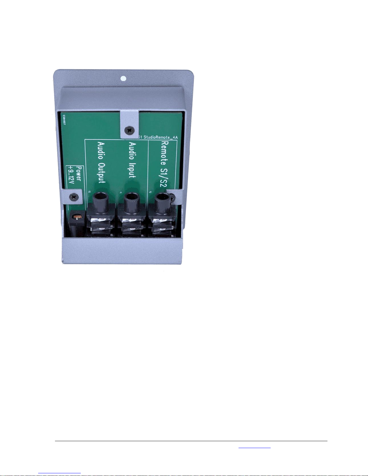
AIRENCE | AIRLITE
REMOTE/SIGNALLING IN MIC MODE.
This useful feature has three important functions:
1. Remote Switch for Cough
2. Remote switch for Talkback or communication
and showing Mic-On Red Light etc.
3. Headphones Amplifier.
The Audio-jack input connector of the Studio
remote unit need to be wired to the master of the
Airence/Airlite, Guest or Announcer outputs or
whatever suits your purpose mostly. The volume
of this signal can now be adjusted with the
potentiometer on the front of the remote.
The audio-jack output connector is connected to
the audio-jack input connector for feeding
through (looping) the audio signal.
The S1/S2 jack connector needs to be wired to
the channel (Remote) of which you want to mute
(cough) the mic input. Use a balanced jack (TRS)
cable for all connections.
A wiring schematic will be shown in the
specification section of this manual.
Power-Jack:
Connect the external power-supply (+ 9 to 12 volt) to the Power-Jack connector.
Be careful, only use the standard D&R Studio remote-Unit power-supply that is part of the delivery.
When in doubt ask your local D&R dealer or a qualified technician.
Do not connect a wrong or damaged power-supply to the Studio remote-Unit to prevent you from electric
shocks. Always use a Class II power supply (without earth pin, double isolated).
Page 7

Operational & Service Manual Studio Remote 1.04
Studio Remote, D&R Phone +31 294 418014, email: info@d-r.nl Page 7
TECHNICAL DETAILS OF CONNECTORS AND LEVELS
Phones Output (Stereo Jack, front)
Tip
Phones Left
> 16 Ohm
Ring
Phones Right
> 16 Ohm
Sleeve
GND
150mW in to 16 Ohm
75mW in to 32 Ohm
45mW in to 64 Ohm
Audio input (RJ45 or Stereo Jack)
on the back of the PCB
Tip
Left
10kOhm
Ring
Right
10kOhm
Sleeve
GND
AXUM | AIRMAX
Head-Phones (headphone RJ45 are connected in parallel.)
Microphone
pin
name
function
pin
name
funtion
1
1A
Audio-Input 1 Left
1
1A
Mic-Output In-Phase
2
1B
Audio-Input 1 Right
2
1B
Mic-Output Out-Phase
3
2A
Audio-Input 2 Left
3
2A
N.C. 6 2B
Audio-Input 2 Right
6
2B
N.C. 5 3A
N.C.
5
3A
LED 1 (TTL)
4
3B
N.C.
4
3B
Switch 1 (TTL)
7
4A
N.C.
7
4A
LED 2 (TTL)
8
4B
N.C.
8
4B
Switch 2 (TTL)
shielding
Audio GND
shielding
GND reference for for TTL
Always use shielded cat5 cable to prevent hum.
The pin-out is equal to the D&R AirMax and D&R Axum RJ45 audio connections.
AIRLAB | AIRMIX
AIRENCE | AIRLITE
Remote Jack S1 and S2 on the Back PCB
Remote Jack S1/S2 on the Back PCB
pin
name
function
Pin
name
function
Tip
Cough
Connected to Com switch
Tip
Com
Connect to Com switch (TTL)
Ring
Connected to Com switch
Ring
Cough
Connect to Cough switch (TTL)
Sleeve
nc Sleeve
GND
Reference for TTL
Tip
Com
Connected to Cough
switch
Ring
Connected to Cough
switch
Sleeve
nc
Power Jack (back side)
9V DC 100mA
Class II power (without earth pin)
Centre pin
+9V
9 to 12 V DC
Ring
GND
The Power Jack is protect against reverse polarity connection.
Page 8

Operational & Service Manual Studio Remote 1.04
Studio Remote, D&R Phone +31 294 418014, email: info@d-r.nl Page 8
Scale 1:1 Print on A4 scale to 100%
20 mm
20 mm
80 mm
r= 4 mm
71 mm
91 mm
To countersunk front deepen
the grey area 2 mm thick
Cut out to at least
a depth of 50 mm
Cutout Template
Page 9

Operational & Service Manual Studio Remote 1.04
Studio Remote, D&R Phone +31 294 418014, email: info@d-r.nl Page 9
EG Declaration of Conformity
We, D&R Electronica B.V.
Rijnkade 15b
1382S Weesp
The Netherlands
Herewith take the sole responsibility to confirm that this product:
Type designation : Studio Remote (2014)
Kind of equipment : Remote and Headphones-Amplifier
Which refers to this declaration, is in accordance with the following standards or standardized documents:
EMC Directive 89/336/EEG, norm EN55103-1 (E2) EN55103-2 (E2)
Low Voltage Directive 73/23/EEG, norm EN60065
Duco de Rijk
MD
D&R Electronica B.V.
January 2014
Weesp
Page 10

Operational & Service Manual Studio Remote 1.04
Studio Remote, D&R Phone +31 294 418014, email: info@d-r.nl Page 10
Disclaimer:
Due to a policy of continuous product improvement, D&R Electronica Weesp B.V reserves the right to
change specifications, appearance and performance without prior notice.
Since the use of this information, and the conditions by which the products are used are beyond the
control of D&R Electronica Weesp B.V, it is the obligation of the owner and/or the equipment operator to
determine the correct and safe selection, settings and conditions of use of the equipment and products.
To the extent that the law permits, any liability which may be incurred as a result of
the use or future use of a product manufactured or sold by D&R Electronica Weesp B.V is limited to the
cost of repairing or replacing the failed product or component at the discretion of D&R Electronica Weesp
B.V, either within, or outside of warranty period, and does not extend to any loss or damage which may be
caused as a consequence of misuse or failure of the equipment or products.
D&R Electronica Weesp B.V shall not in any event be liable for economic loss of profits including without
limitation any incidental or consequential damage, expenses or other damages arising out of the use or
inability to use the product and/or software even if D&R has been advised of the possibility of such a
damage or for any claim by another party.
You agree to indemnify, hold harmless, and defend D&R Electronica Weesp B.V., its parent, and their
licensors, suppliers, officers, directors, employees, agents, affiliates, subsidiaries (collectively "Indemnified
Parties") from and against any and all liability incurred by or made against the Indemnified Parties in
connection with any claim arising from or related to your use.
Duco de Rijk
president
 Loading...