


DR
SAFETY & OPERATING INSTRUCTIONS
Models: SPRINT
®
TRIMMER/MOWER™
®
, PRO, and PRO-XL SELF- PROPELLED
Serial No.
Order No.
Read and understand this manual and all instructions before operating the DR TRIMMER/MOWER.
Original Language
DR Power Equipment
Toll-free phone: 1-800-DR-OWNER (376-9637)
Fax: 1-802-877-1213
Website: www.DRpower.com

Table of Contents
y
Chapter 1: General Safety Rules ............................................................................................................................................................ 3
Chapter 2: Setting Up The DR TRIMMER/MOWER ............................................................................................................................ 6
Chapter 3: Operating The DR TRIMMER/MOWER ............................................................................................................................. 12
Chapter 4: Maintaining The DR TRIMMER/MOWER .......................................................................................................................... 19
Chapter 5: Troubleshooting .................................................................................................................................................................. 32
Chapter 6: Parts Lists, Schematic Diagrams And Warranty ................................................................................................................ 36
Conventions used in this manual
This indicates a hazardous situation, which, if not avoided, could result in death or serious injury.
This indicates a hazardous situation, which, if not avoided, could result in minor or moderate injury.
This information is important in the proper use of your machine. Failure to follow this instruction could result in damage
to
our machine or property.
Serial Number and Order Number
A Serial Number is used to identify your machine and is located on the Serial Number Label on your machine. An Order Number
is used to check and maintain your order history and is located on the upper left portion of your packing slip. For your
convenience and ready reference, enter the Serial Number and Order Number in the space provided on the front cover of this
manual.
Additional Information and Potential Changes
DR Power Equipment reserves the right to discontinue, change, and improve its products at any time without notice or obligation
to the purchaser. The descriptions and specifications contained in this manual were in effect at printing. Equipment described
within this manual may be optional. Some illustrations may not be applicable to your machine.
2 DR
®
TRIMMER/MOWER

Chapter 1: General Safety Rules
#
#
#
#
#
y)
Read this safety & operating Instructions manual before you use the DR TRIMMER/MOWER. Become familiar with the operation
and service recommendations to ensure the best performance from your machine. If you have any questions or need assistance,
please contact us at www.DRpower.com or call toll-free 1-800-DR-OWNER (376-9637) and one of our Technical Support
Representatives will be happy to help you.
Labels
Your DR TRIMMER/MOWER carries prominent labels as reminders for its proper and safe use. Shown below are copies of all the
Safety and Information labels that appear on the equipment. Take a moment to study them and make a note of their location on
your DR TRIMMER/MOWER as you set up and before you operate the unit. Replace damaged or missing safety and information
labels immediately.
193201
127811
#148221
153081
#240641
215001 (non self-propelled only)
#136491
WHEEL CLUTCH
136501 (self-propelled onl
Protecting Yourself and Those Around You
This is a high-powered machine, with moving parts operating with high energy at high speeds. You must operate the machine
safely. Unsafe operation can create a number of hazards for you, as well as anyone else in the nearby area. Always take the
following precautions when using this machine:
Keep in mind that the operator or user is responsible for accidents or hazards occurring to other people, their property, and
themselves.
Always wear protective goggles or safety glasses with side shields while mowing to protect your eyes from possible thrown
debris.
Avoid wearing loose clothing or jewelry, which can catch on the mower’s moving parts.
We recommend wearing gloves while mowing. Be sure your gloves fit properly and do not have loose cuffs or drawstrings.
Wear shoes with non-slip treads when using your DR TRIMMER/MOWER. If you have safety shoes, we recommend wearing
them. Do not use the machine while barefoot or wearing sandals with exposed toes or heels.
Wear long pants while operating the DR TRIMMER/MOWER.
Use ear protectors or ear plugs rated for at least 20 dba to protect your hearing.
Keep bystanders at least 50 feet away from your work area at all times. The tips of the cutting cords on the DR
TRIMMER/MOWER can throw sticks, small stones, gravel, and bits of debris over long distances at great velocity. Do not
travel over loose materials such as gravel or mulch with the trimmer head spinning. Doing so could cause personal injury or
property damage from thrown objects. Release the bail bar to stop the spinning cords and shut off the engine when another
person or pet approaches.
Never tamper with safety devices. Check their proper operation regularly.
Never operate the machine when under the influence of alcohol, drugs, or medication.
In an emergency, to quickly stop the cutting cords, remove your hand from the bail bar.
CONTACT US AT www.DRpower.com 3

Operating the Mower Safely
This is a high-powered machine, with moving parts operating with high energy at high speeds. You must operate the machine
safely. Unsafe operation can create a number of hazards for you, as well as anyone else in the nearby area. Always take the
following precautions when using this machine:
Never allow people who are unfamiliar with these instructions to use the DR TRIMMER/MOWER. Allow only responsible
individuals who are familiar with these rules of safe operation to use your machine.
Never place your hands, feet, or any part of your body on or under the mower deck in the path of the spinning cords, belt,
pulleys, or near the discharge opening while the engine is running. Keep area of discharge clear of people, animals, buildings,
glass, or anything else that will obstruct clear discharge, cause injury, or damage.
Your DR Trimmer/Mower is a powerful tool, not a plaything. Exercise extreme caution at all times. The design of your
machine is for trimming and mowing grass, weeds, and other growth as specified in this manual. Do not use it for any other
purpose.
Whenever you leave the operating position to make adjustments, change cords or if you have to remove grass or debris from
the underside of the deck, always shut off the engine and wait five (5) minutes to allow parts to cool. Remove the key, if so
equipped, and disconnect the spark plug wire and keep the wire away from the spark plug to prevent accidental starting.
When operating over uneven terrain and slopes, use extreme caution to ensure solid and firm footing. Keep a firm hold on
the handlebar and walk, never run.
Stop the cutting cords when crossing gravel drives, walks, or roads.
Never operate your unit on a slippery, wet, or muddy surface. Exercise caution to avoid slipping or falling.
Always operate the mower from behind the handlebar. Never pass or stand on the discharge side of the machine when the
engine is running or cutting cords are spinning.
Never, under any conditions, remove, bend, cut, fit, weld, or otherwise alter standard parts on the DR TRIMMER/MOWER.
This includes all shields and guards. Modifications to your machine could cause personal injuries and property damage and
will void your warranty.
If the cutting cords strike a foreign object or if your machine should start making an unusual noise or vibration, stop the
engine and wait five (5) minutes for all moving parts to come to a complete stop and cool. Vibration is generally a warning of
trouble. Disconnect the spark plug wire and inspect for damage. Clean and repair and/or replace damaged parts.
While using the DR TRIMMER/MOWER, do not hurry or take things for granted. When in doubt about the equipment or your
surroundings, stop the machine and take the time to look things over. Make sure that you have 100% control of the mower at
all times.
Watch for traffic when mowing near roadways.
Use the machine only in daylight.
Be cautious when using your DR TRIMMER/MOWER around fencing, wires, ropes, and hoses. It is possible that these and
other debris can become wound around the line plates of the machine, potentially damaging the bearings or injuring you.
Do not operate the DR TRIMMER/MOWER on slopes greater than 20 degrees.
Keep all nuts and bolts tight and keep the equipment in good operating condition.
Safety for Children and Pets
Tragic accidents can occur if the operator is not alert to the presence of children and pets. Children are often attracted to the
machine and the mowing activity.
precautions:
Keep children and pets out of the working area and under the watchful care of a responsible adult.
Be alert and turn the machine off if children or pets enter the work area.
Never allow children to operate the DR TRIMMER/MOWER.
Use extra care when approaching blind corners, shrubs, trees, or other objects that may obscure your vision.
4 DR
®
TRIMMER/MOWER
Never
assume that children will remain where you last saw them. Always follow these

Safety with Gasoline - Powered Machines
Gasoline is a highly flammable liquid. Gasoline also gives off flammable vapor that can be easily ignited and cause a fire or
explosion. Never overlook the hazards of gasoline. Always follow these precautions:
Never run the engine in an enclosed area or without proper ventilation as the exhaust from the engine contains carbon
monoxide, which is an odorless, tasteless, and deadly poisonous gas.
Store all fuel and oil in containers specifically designed and approved for this purpose and keep away from heat and open
flame, and out of the reach of children.
Replace rubber fuel lines and grommets when worn or damaged and after 5 years of use.
Fill the gasoline tank outdoors with the engine off and allow the engine to cool completely. Don't handle gasoline if you or
anyone nearby is smoking, or if you're near anything that could cause it to ignite or explode. Reinstall the fuel tank Cap and
fuel container cap securely.
If you spill gasoline, do not attempt to start the engine. Move the machine away from the area of the spill and avoid creating
any source of ignition until the gas vapors have dissipated. Wipe up any spilled fuel to prevent a fire hazard and properly
dispose of the waste.
Allow the engine to cool completely before storing in any enclosure. Never store a machine that has gas in the tank, or a fuel
container, near an open flame or spark such as a water heater, space heater, clothes dryer or furnace.
Never make adjustments or repairs with the engine running. Shut down the engine, wait 5 minutes, disconnect the spark plug
wire, keeping it away from the spark plug to prevent accidental starting before making adjustments or repairs.
Never tamper with the engine’s governor setting. The governor controls the maximum safe operation speed and protects the
engine. Over-speeding the engine is dangerous and will cause damage to the engine and to the other moving parts of the
machine. If required, see your authorized dealer for engine governor adjustments.
Keep combustible substances away from the engine when it is hot.
Never cover the machine while the muffler is still hot.
Do not operate the engine with the air cleaner or cover over the carburetor air-intake removed, except for adjustment.
Removal of such parts could create a fire hazard. Do not use flammable solutions to clean air filter.
The muffler and engine become very hot with use and can cause a severe burn; do not touch. Allow the engine to cool before
refueling, doing maintenance, or making adjustments.
Do not mow in the rain. Water on the spark plug may cause the engine to stall.
Keep combustible substances away from the engine when it is hot.
Never cover the machine while the muffler is still hot.
A Note to All Users
Under California law, and the laws of some other states, you are not permitted to operate an internal combustion engine using
hydrocarbon fuels without an engine spark arrester. This also applies to operation on US Forest Lands. All DR
TRIMMER/MOWERS shipped to California, New Mexico and Washington State are provided with spark arresters. Failure of the
owner or operator to maintain this equipment in compliance with state regulations is a misdemeanor under California law and
may be in violation of other state and/or federal regulations. Contact your State Park Association or the appropriate state
organization for specific information in your area.
No list of warnings and cautions can be all-inclusive. If situations occur that are not covered by this manual, the operator must
apply common sense and operate this DR TRIMMER/MOWER in a safe manner. Contact us at www.DRpower.com or call 1-800DR-OWNER (376-9637) for assistance.
®
CONTACT US AT www.DRpower.com 5

Chapter 2: Setting Up The DR TRIMMER/MOWER
A
l
A
It may be helpful to familiarize yourself with the controls and features of your DR TRIMMER/MOWER as shown in Figure 1 before
beginning these procedures.
If you have any questions at all, please feel free to contact us at www.DRpower.com.
DR TRIMMER/MOWER Controls and Features
Bail Bar
®
PTA
Lever
Bail Bar
Spring
(Key shipped
here)
Throttle
Handlebar
djuster
Key
Switch
Side Shield
SPRINT
Recoil Starter
and PRO Models
Oil Fil
Fuel Fill
Primer Bulb
Cutting Cord
Mow-Ball
®
Support
Wheel Clutch Lever
Bail Bar
Bail Bar Spring
(Key shipped here)
6 DR
®
TRIMMER/MOWER
Throttle
Recoil Starter
Fuel Fill
Primer Bulb
Figure 1
Key Switch
Oil Fill
Handlebar
djuster
Side Shield
PRO-XL SELF-PROPELLED Model
Cutting Cord
Mow-Ball
Support
®

Specifications
k
l
l
MECHANICAL SPECIFICATIONS
Engine
Wheels
Frame
Cutting Width
Cutting Height
Machine Width
Machine Weight
Sprint Pro Pro-XL Self-Propelled
See Engine Owners Manual for
details
See Engine Owners Manual
for details
See Engine Owners Manual for
details
14" Resin 16" Resin 14" Resin
Steel Steel Steel
20" 20" 20"
1-1/2" to 4" 1-1/2" to 4" 1-1/2" to 5"
23" 23" 22"
68 lbs. Manual Start, 75 lbs.
Electric Start
70 lbs. Manual Start, 77 lbs.
Electric Start
90 lbs. Electric Start
Unpacking the DR TRIMMER/MOWER
Stabilize the shipping box at floor level in a clean flat area before attempting to unpack the Trimmer/Mower. For your safety we
recommend you have two people for the following procedures.
Tools Needed:
Utility Knife
5/8" Wrench
Wire Cutters
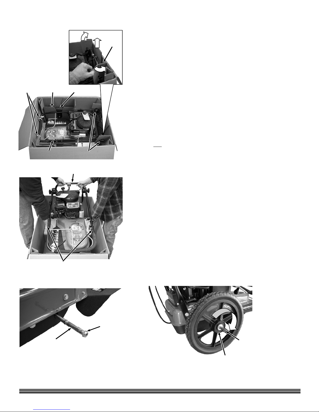
1. Position the Shipping Box at floor level in a clean flat area with the text on
the side of the Box right side up (Figure 2).
2. With a Utility Knife, cut the Tape that secures the Box Flaps at both ends and
along the center.
Parts Supplied in Box (Figure 3):
DR TRIMMER/MOWER
Trimmer Wheels
Product Package (plastic bag with owner's manual, engine manual, head
locking tool, and other product information)
Trimmer Cord Pack
Two Keys, for electric-starting models (located just below the Bail Bar
Spring of the Trimmer)
Compare the contents of the Shipping Box with the “Parts Supplied” list above.
If you have any questions please contact us at www.DRpower.com or call 1-800DR-OWNER (376-9637) for assistance.
3. Remove the Product Package and Trimmer Cord Pack from the Shipping
Box.
Figure 2
Bail Bar
Spring
Keys
Whee
Trimmer
Cord
Pac
Figure 3
Tape
DR
Trimmer/
Mower
Whee
Product
Package
CONTACT US AT www.DRpower.com 7
r
Cable Ties
s
A
Wheel
Insert
Wheel
Hand
Knob
Insert
4. Hold the Upper Handlebar and use Wire Cutters to cut the Cable Ties that
attach the Upper Handlebar to the Box (Figure 4).
5. Remove the Wheels and Wheel Inserts from the Shipping Box.
6. Rotate the flaps out over the Hand Knobs as you pull the Hand Knob Insert
from the back of the Box.
NOTE: You will need two people to lift the Trimmer from the Box. Do not lift on
the Upper Handlebar. Lift from the Lower Handlebar and bottom of the machine.
7. With help from another person, lift the Trimmer from the Shipping Box
(Figure 5).
8. Position the Trimmer on the ground so you have access to the ends of the
Axle and remove the Locknuts from both ends of the Axle (Figure 6). They
should be loose enough to remove by hand.
NOTE: The right and left side of the machine is referenced from the Operating
position.
Figure 4
Figure 5
Upper
Handlebar
Do Not Lift on
Upper Handleba
Handlebar
Hand Knob
Lower Handlebar
9. For the non
self-propelled Trimmer, slide the Wheels onto the Axle with the
smooth side of the Hub facing out and go to step 12.
NOTE: On the self-propelled Trimmer the right side wheel has a red mark on the
smooth side of the Hub and will face away from the Trimmer Body. The left side
wheel has a blue mark on the smooth side of the Hub and will also face away from
the Trimmer Body.
10. For the self-propelled Trimmer, install the right side wheel onto the Axle by
rotating it clockwise as you slide it onto the Axle (Figure 7).
NOTE: A plastic plug will come out of the Wheels as you slide them on. Save this
plug to insert back into the Wheels if they need to be removed in the future.
11. Install the left side wheel onto the Axle by rotating it counter-clockwise as
you slide it onto the Axle.
12. Secure the Wheels to the Axle with the two Locknuts using a 5/8" Wrench.
You may need to hold the axle with Locking Pliers to keep it from turning
(use a rag or similar to protect the Shaft from damage).
Locknut
xle (Right Side)
Figure 6
8 DR
®
TRIMMER/MOWER
Figure 7
Plastic
Insert
Red Mark on Outside of Hub
(For Right Side Wheel)

13. Lift the Upper Handlebar until it is near the operator position and tighten
A
s
the Handlebar Adjuster Knobs (Figure 8). The correct operating position is
about waist high and can be adjust for comfort.
NOTE: Ensure that the teeth of the Handlebar Adjuster mesh correctly as you
tighten the Knobs.
Do not discard your Trimmer packaging materials. Store the shipping box and
all inserts in a dry, safe area for future use. If there are any questions, contact us
at www.DRpower.com or call 1-800-DR-OWNER (376-9637).
Meshing
Teeth
If for any reason you need to ship the machine back to us, use the original
packaging and follow the reverse order of the previous unpacking instructions.
Installing the Trimmer Cords
There are two installation points on each Line Plate. Each point is 180 degrees
apart. Always install two Cords, one opposite the other at the same height.
14. Insert the ends of the Cords into the side openings in the Line Plate
(Figure 9).
NOTE: The photo shows the Cords being installed at the third opening from the
bottom. This allows for a 2-1/2" cutting height. Refer to “The DR
Trimmer/Mower Cutting Cords” section in Chapter 3 for more detailed
information and for setting the cutting height and other important Cord
details.
15. Push the Cord through until the ends come out the center hole in the Line
Plate. Adjust the Cords so the tips are even.
16. Pull the Cords under the loop and push the loop up into the Line Plate
groove above them (Figure 10) and then pull the Cords tight.
If the tips of the cords are not even, it can cause unbalance of the trimmer
and will result in increased vibration.
Handlebar
djusting Knob
Figure 8
Side
Openings
Cord
Center
Opening
Figure 9
Cord End
Figure 10
CONTACT US AT www.DRpower.com 9

Adding Oil and Gasoline
You must add oil before starting the engine. This machine is shipped without oil. Traces of oil may be in the reservoir from
factory testing, but
avoid overfilling.
To get an accurate reading when checking the oil level:
- the machine should be on a level surface.
- the dipstick should
Tip: To avoid confusion, we recommend leaving the caps ON the Fuel and Oil Fills until you are ready to pour either gasoline or
oil into the correct Fill.
NOTE: You will need approximately 15 to 22 ounces of SAE 30 high detergent oil depending on Engine type. Use only SAE 30 high
detergent oil classified “For Service SF, SG, SH, SJ” or higher. Do not use special additives. Other types of oil could cause
problems with the operation of your machine. Please refer to your Engine Owner’s Manual for detailed information on oil
quantity, and cold temperature oil specifications.
Gas Fill
you must add oil before starting the engine. Fill the reservoir slowly, checking the level frequently to
be screwed down to ensure an accurate oil level reading.
1. Place the machine on a level surface and initially add 1/2 of the SAE 30 High
Oil Fill
Detergent oil (recommended by the Engine Manufacturer) into the Oil Fill
(Figure 11) and wait one (1) minute for the oil to settle
2. Check the Dipstick and continue adding a few ounces of oil at a time,
rechecking the Dipstick until the oil reaches the fill mark. Be careful not to
overfill.
Figure 11
Negative (-) Battery
Terminal
Figure 12
Battery Wire
Fill the fuel tank outdoors or in a well-ventilated area, away from sparks, open
flames, pilot lights, heat, and other ignition sources.
NOTE: Discard the blue Protective-Shipping Cap provided by some Engine
Manufacturers. You will find this Protective-Shipping Cap under the Fuel Fill Screw
Cap or in the tank Filler Tube. See your Engine Owner’s Manual for more fuel
information.
3. Fill the Fuel Tank with fresh, unleaded gas (with a minimum of 85 Octane),
to not more than a 1/4" from the bottom of the Fill Neck to allow for Fuel
expansion. Be careful not to overfill and reinstall the Cap before starting the
Engine. See your Engine Owner’s Manual for more information.
NOTE: To refill the Fuel Tank, turn the Engine OFF, and let the Engine cool at least
two (2) minutes before removing the Fuel Fill Cap.
Connecting the Battery Wire (Electric-Starting Models Only)
We ship all Electric-Starting Trimmers with the negative Battery wire
disconnected. This prevents the Battery from discharging during shipment.
Before using your Trimmer, you must connect the Battery wire.
1. Connect the black wire by pushing the plastic connector onto the negative
(–) Battery terminal (Figure 12).
NOTE: The red wire should already be attached to the positive terminal.
10 DR
®
TRIMMER/MOWER

Adjusting the Handlebar
A
r
A
A
It is important to find a Handlebar height that allows the Mow-Ball Support to
hover just above the ground and remain balanced so you do not have to push
down or pull up on the Handlebar. When in use, proper adjustment is critical to
best performance.
At the proper height, your hands should rest at a comfortable level and the front
end of the Trimmer should glide easily on the Mow-Ball Support as shown in
Figure 22 on page 16. You may find you like different Handlebar heights for
different mowing conditions.
There are two ways to adjust the height of the Handlebar outlined in the
following steps:
1. Loosen both the Adjustment Knobs and move the Handlebar up or down
until the adjustment is the same on both sides. Use the Notches on the
Adjusters (Figure 13 “A”) to measure how many Teeth you have moved away
from the center. When you have found a comfortable height, tighten the
Adjustment Knobs securely.
2. For additional height adjustment options, there are two holes in the Upper
and Lower Handlebars where the Adjustment Knobs are located (Figure 13
“B”). Most people start with the Handlebars set in the Lower holes of both
the Upper and Lower Handlebar. You can adjust the height up or down by
removing the Adjustment Knob Assembly and repositioning the Handlebars
to a higher or lower hole. Be sure the Notches in the two Adjusters line up
when you reassemble them (Figure 13 “A”). You may need to adjust the
PTA Lever as well. See the next section.
Lower Handlebar
Bolt
Inside
Adjuster
Upper
Handlebar
Lower
Handlebar
Upper
Handlebar
Notches
Lined Up
“A”
djustment
Knob
Outside
djuste
Height
djustment
Holes
Adjusting the PTA (Parallel Trimming Action) Lever - SPRINT and
PRO
Before performing any adjustment, maintenance procedure or inspection, stop
the engine, wait five (5) minutes to allow parts to cool and disconnect the
spark plug wire, keeping it away from the spark plug.
It is easy to adjust the PTA feature. If you have moved the Handlebar up or
down, the PTA (Parallel Trimming Action) Lever may need adjustment. When
the PTA feature is properly engaged, there should be just a little slack in the
cable. For more information on PTA, please read the section called Using
PTA (Parallel Trimming Action) in Chapter 3.
1. Loosen the Knob on the PTA Control by turning it counterclockwise (Figure
14).
2. Move the Assembly up the Handlebar to tighten the cable or down the
Handlebar to loosen it.
3. Retighten the Knob.
“B”
Figure 13
Loosen
Knob
Slide Up or
Down to adjust
Figure 14
CONTACT US AT www.DRpower.com 11

Chapter 3: Operating The DR TRIMMER/MOWER
You may find it helpful to review the DR TRIMMER/MOWER Controls and Features (Figure 1 on page 6) before reading this
chapter.
The design of your machine is for trimming and mowing grass, weeds, and other growth as specified in this manual. Do not
use it for any other purpose as it could cause serious injury.
Contact with internal rotating parts will cause serious personal injury. Never put hands, face, feet, or clothing under the
mower deck or discharge opening at any time.
Before performing any adjustment, maintenance procedure or inspection, stop the engine, wait five (5) minutes to allow parts
to cool. Disconnect the spark plug wire, keeping it away from the spark plug.
Before Starting the Engine
1. Check the oil level every time you use the DR TRIMMER/MOWER (Figure 11 on page 10).
2. Check the gas level (Figure 11 on page 10).
3. Remove any debris buildup from the underside of the machine.
It is important for proper operation to keep the top of the engine clear of grass and debris at all times so the engine can pull air
through to stay cool. If the top of the engine is clogged then the engine could overheat causing engine damage.
Electric-Starting
NOTE: Use the following steps with Electric-Starting models only.
1. Push the Throttle Control Lever on the right side of the Handlebar (Figure 1 on page 6) all the way forward to the RABBIT
(Fast) position.
2. If your model has an Engine Primer, push the Primer Bulb IN (Figure 1 on page 6) and completely release it, lifting your finger
and letting it pop back to its original position. Repeat three to four times.
NOTE: Priming is usually not necessary when restarting a warm Engine. In cool weather, you may need to repeat the priming operation.
3. Turn the Key (Figure 1 on page 6) to the START position until the Engine starts, then release. The Key will snap back to the
RUN position and the Engine will continue to run.
NOTE: Do not engage the Bail Bar (Trimmer Head Control) or the Wheel Clutch Lever (Self-Propelled model only) until after the Engine
has started.
If the engine fails to start after TEN (10) seconds of continuous cranking, turn the key to the off position and allow the starter
motor to cool. Check the cause of hard starting; See Chapter 5 - Troubleshooting.
Manual-Starting
NOTE: You may use this starting method with both Manual and Electric-Starting models.
1. Push the Throttle Control Lever on the right side of the Handlebar (Figure 1 on page 6) all the way forward to the RABBIT
(Fast) position.
2. If your model has an Engine Primer, push the Primer Bulb IN (Figure 1 on page 6) and completely release it, lifting your finger
and letting it pop back to its original position. Repeat three to four times.
12 DR
®
TRIMMER/MOWER

NOTE: Priming is usually not necessary when restarting a warm engine. In cool weather, you may need to repeat the priming procedure.
3. Grasp the Recoil Starter Handle (Figure 1 on page 6) and slowly pull until you feel resistance. Let the cord retract a little bit,
then pull the cord rapidly to start the Engine. One or two pulls usually starts the DR TRIMMER/MOWER. It may be necessary
to repeat the priming operation if the machine does not start within two pulls.
NOTE: Do not engage the Bail Bar (Trimmer Head Control) or the Wheel Clutch Lever (Self-Propelled model only)
until after the Engine has started.
Stopping the Engine
1. Move the Throttle Control Lever (Figure 1 on page 6) all the way back past the TURTLE (Slow) position to the STOP position.
NOTE: If you have an Electric-Starting model, please note that the Key does not stop the Engine. You must move the throttle control
lever to the stop position to stop the Engine for both Electric and Manual-Starting models.
2. For Electric starting models, remove the Key for safety. The Key has a pressure lock that prevents it from vibrating loose
during operation. To remove the Key, push it in and then quickly and firmly pull it out. If the Key becomes difficult to remove,
apply a penetrating Oil (such as WD 40) into the Keyhole.
Engaging the Trimmer Head
1. Bring the Bail Bar toward you and grip it together with the Handlebar (Figure 1 on page 6). Keep holding the Bail Bar to the
Handlebar. The Cutting Cords will rotate and will continue to rotate until you release the Bail Bar.
Stopping the Cords from Spinning
1. Release the Bail Bar from the Handlebar. The Trimmer Head will stop spinning while the Engine continues to run.
Engaging the Wheel Drive - SELF-PROPELLED model
NOTE: The SELF-PROPELLED DR TRIMMER/MOWER has a variable speed forward Transmission.
1. Gently squeeze the Clutch Lever (Figure 1 on page 6) to engage the Wheel Drive.
NOTE: The more you squeeze the Clutch Lever, the faster the Trimmer will go.
2. Release the Clutch Lever to stop the Wheel Drive.
Using PTA® (Parallel Trimming Action) – SPRINT® and PRO models only
Your DR TRIMMER/MOWER’S PTA feature allows you to move the machine in a straight line while the Trimmer Head is both
pivoted and tilted to the left for better access to fence lines and other obstacles. PTA allows you to trim in difficult areas without
having to pull the machine back and forth.
The following two sections explain how to use PTA and how to return your Trimmer to Normal operation after using PTA.
Use caution when edging along gravel paths and driveways. Flying debris can cause serious damage and injury.
When using PTA, you should install the cutting cords in one of the bottom four line plates only. Using the upper line plates may
cause the cords to hit the wheel. For more information, see the DR Trimmer/Mower Cutting Cords on page 15.
CONTACT US AT www.DRpower.com 13
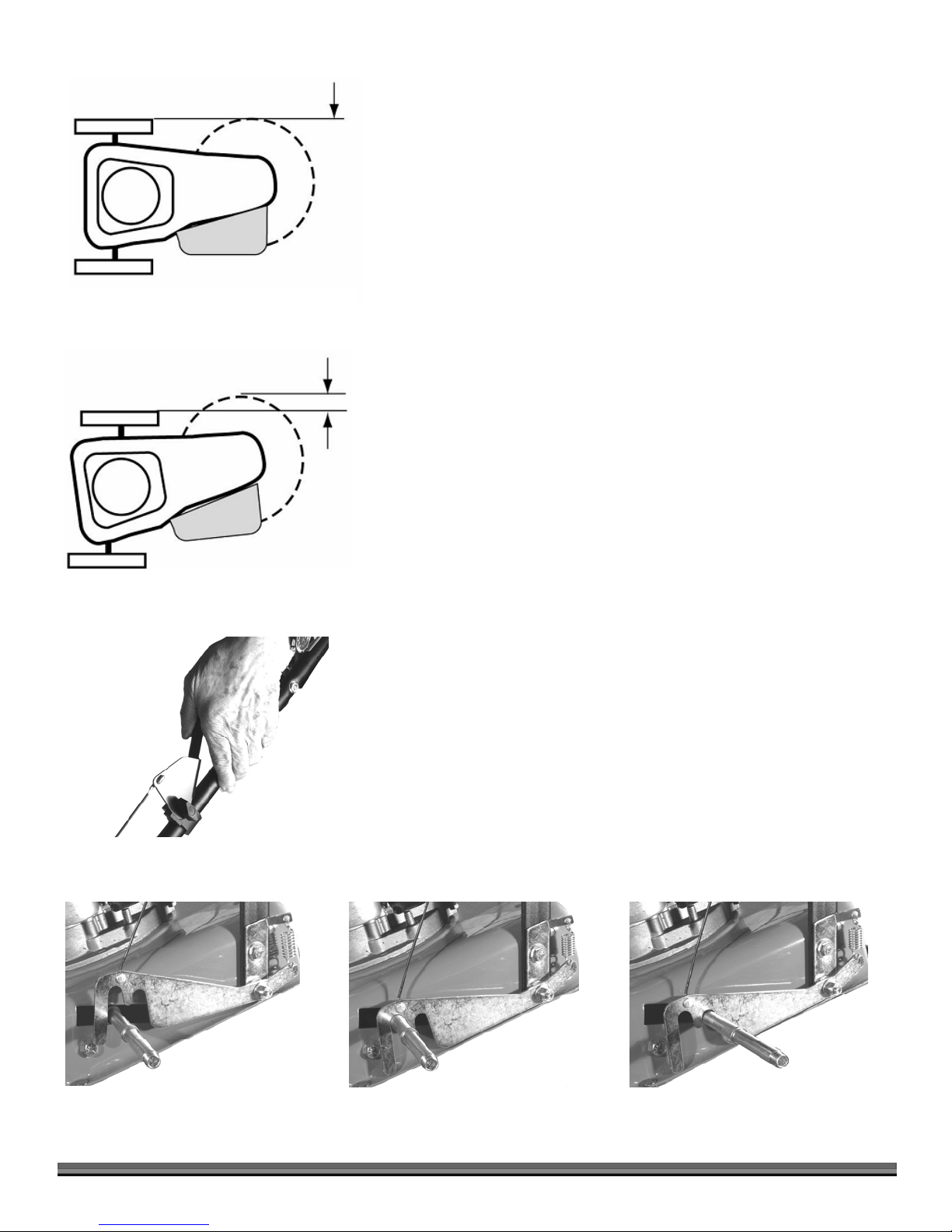
NOTE: In PTA mode, the Trimmer’s Wheels stay straight while the Trimmer
Head tilts (Figure 15). The Cutting Cords extend beyond the wheelbase in the PTA
mode, allowing you to easily cut under obstacles. The Trimmer Head and the
Cutting Cords also tilt slightly in PTA mode so you can edge and trim along
gardens, paths, and driveways. When using PTA along garden edges, fences, and
buildings, we recommend making your first pass with the DR TRIMMER/MOWER
in the Normal mowing position, staying 4 to 8 inches from the obstacle; and then
return for another pass with the machine in PTA mode.
Figure 15
Normal Mode
PTA
Mode
Cords
Extended
Engaging PTA®
1. Stand in the Operator’s position.
2. Pull the PTA Lever (Figure 16) against the Handlebar and hold it there.
This unlocks the Axle (Figure 17).
NOTE: Figure 17 shows the Axle with the Wheel removed for clarity.
3. Push down on the Handlebar to tip the nose of the machine a few inches off
the ground. Balancing the weight of the machine on the Wheels makes it
easier to pivot the front of the Trimmer to the left.
4. While continuing to hold the PTA Lever down, grip the sides of the
Handlebar while pulling up with the right hand and pushing down with the
left, swinging the front of the Trimmer to the left.
5. Release the PTA Lever. This will lock the Axle in PTA mode (Figure 17).
Returning to Normal Mode
1. Pull the PTA Lever (Figure 16) against the Handlebar and hold it there.
2. Push down on the Handlebar to tip the nose of the machine up a few inches
off the ground.
3. While continuing to hold the PTA Lever down, grip the sides of the
Handlebar while pulling up with the left hand and pushing down with the
right, swinging the front of the Trimmer to the right, and stopping at center.
Figure 16
PTA
14 DR
Lever Unlocked
®
TRIMMER/MOWER
4. Release the PTA Lever. This locks the Axle in the Normal operation mode
(Figure 17).
Lever locked in PTA
PTA
Figure 17
PTA
Lever locked in Normal Mode

The DR TRIMMER/MOWER Cutting Cords
s
Out Here
Out Here
Before performing any adjustment, maintenance procedure or inspection, stop
the engine, wait five (5) minutes to allow parts to cool and disconnect the
spark plug wire, keeping it away from the spark plug.
Running the trimmer with only one cord installed, cords of unequal length or
cords installed at other than 180 degrees apart can cause excessive vibration and
may damage the machine.
Figure 18 illustrates the Cords installation on the Line Plates. It shows the Line
Plate from a top view. It may look complicated, but once you have done it a
couple of times, it’s easy. There are two installation points on each Line Plate.
Each point is 180 degrees apart. Always install two Cords, one opposite the
other.
Installing Cords
Reference Figures 18-20 for Cord installation. Your DR TRIMMER/MOWER
shipped from the factory with the Cords installed in this manner.
In Here
In Here
Figure 18
Top View
Out Here
In Here
In Here
Out Here
Side
Openings
When using PTA
®
, install the cutting cords in one of the bottom four line
plates. Installing the cutting cords on the upper line plates can cause the
cord to hit the wheel. For more information on using PTA
®
, see using PTA®
on page 13.
NOTE: After you install the Cords, and before trimming, engage the Cutting Head
with the Engine running and spin new Cords for a few seconds so they pull
tight and are set.
1. Insert the ends of the Cord into the side openings in the Line Plate (Figure
19).
2. Push the Cord through until the ends come out the center opening in the
Line Plate. Adjust the ends so the tips are even.
3. Pull the ends of the Cord under the loop and push the loop up into the Line
Plate groove above them (Figure 20) and then pull the ends tight.
Cord
Center
Opening
Figure 19
Cord End
Figure 20
CONTACT US AT www.DRpower.com 15
 Loading...