

Page 1
DR
SAFETY & OPERATING INSTRUCTIONS
Models: Premier
®
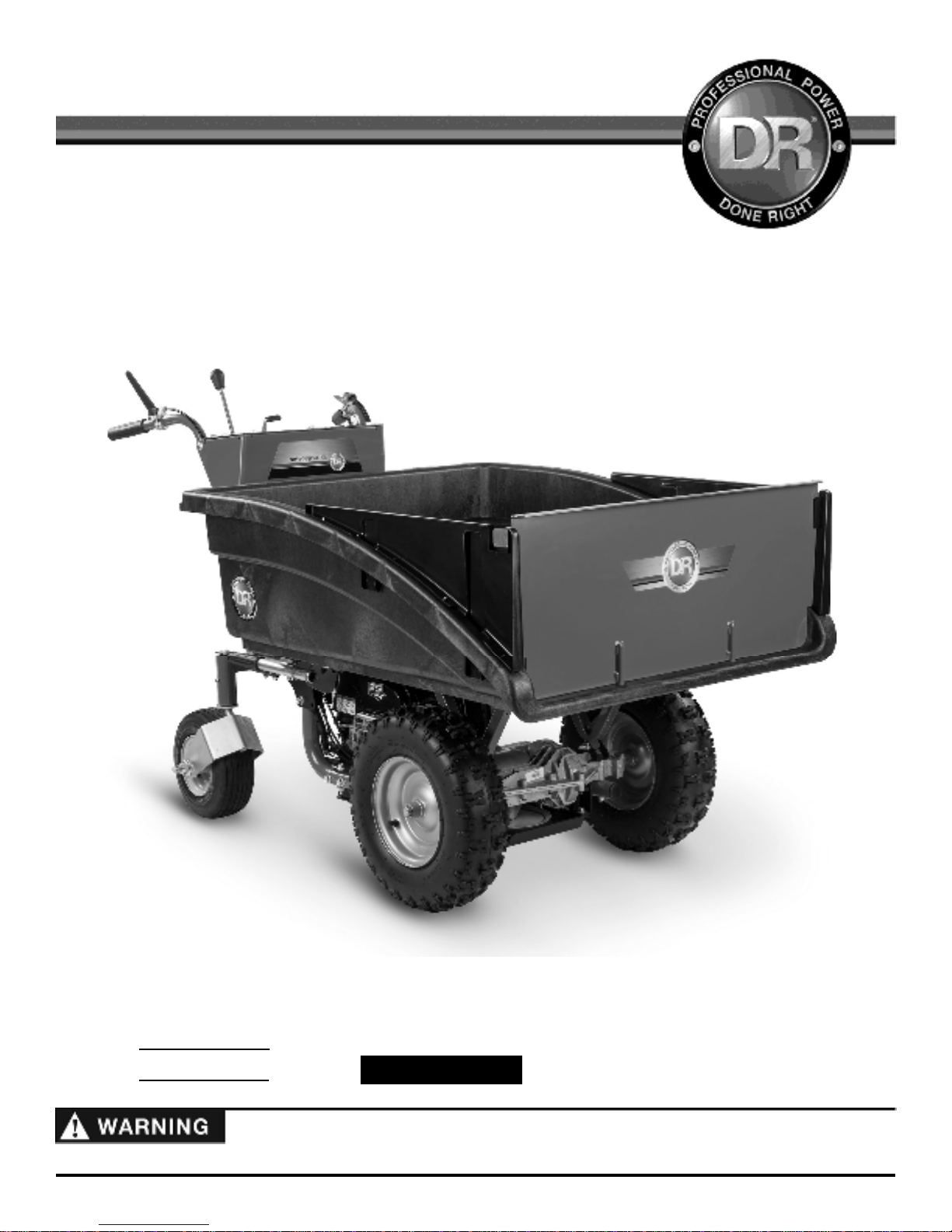
POWERWAGON
Pro
Pro-XL
Serial No.
Order No.
Read and understand this manual and all instructions before operating the DR POWERWAGON.
Original Language
DR Power Equipment
Toll-free phone: 1-800-DR-OWNER (376-9637)
Fax: 1-802-877-1213
Website: www.DRpower.com
Page 2
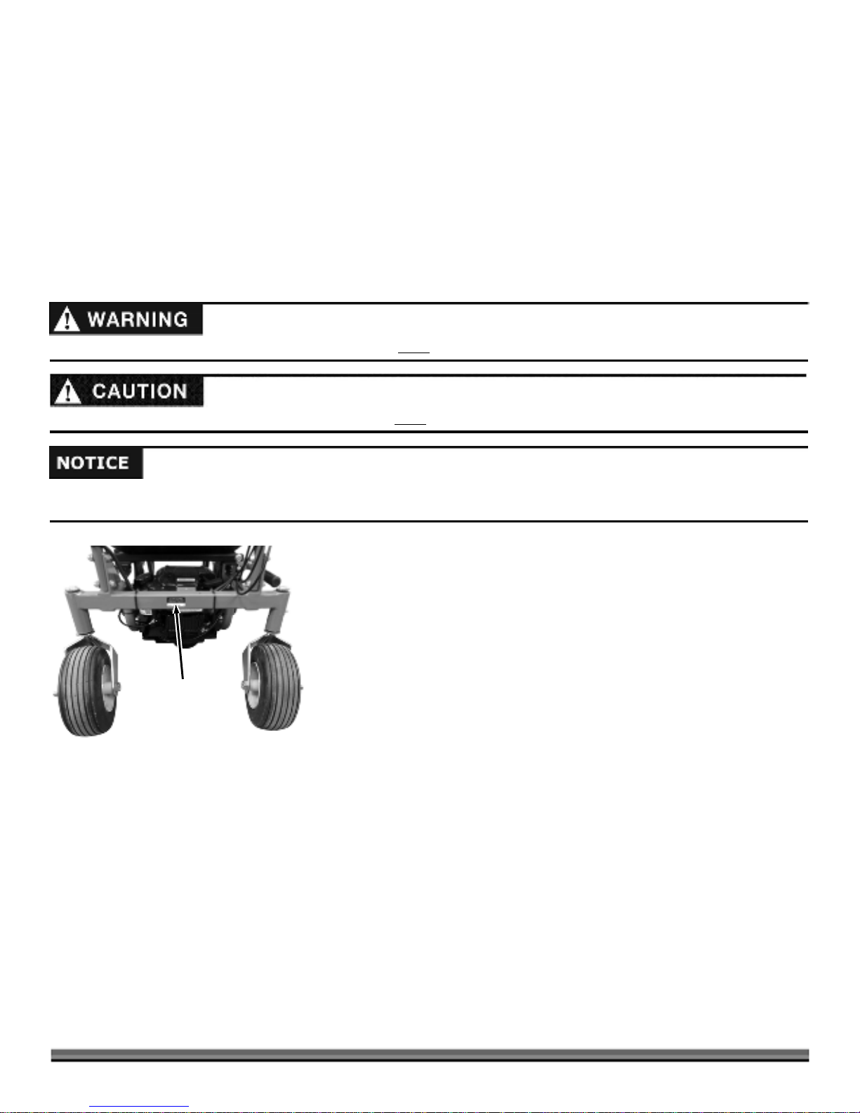
Table of Contents
Chapter 1: General Safety Rules ............................................................................................................................................................ 3
Chapter 2: Setting Up The DR POWERWAGON .................................................................................................................................. 7
Chapter 3: Operating The DR POWERWAGON ................................................................................................................................... 17
Chapter 4: Maintaining The DR POWERWAGON ............................................................................................................................... 21
Chapter 5: Troubleshooting .................................................................................................................................................................. 29
Chapter 6: Parts Lists and Schematic Diagrams .................................................................................................................................. 32
Conventions used in this manual
This indicates a hazardous situation, which, if not followed, could
This indicates a hazardous situation, which, if not avoided, could result in minor or moderate injury.
This information is important in the proper use of your machine. Failure to follow this instruction could result in damage to your
machine or property.
result in death or serious injury.
Serial Number and Order Number
A Serial Number is used to identify your machine and is located on the Serial
Number Label on your machine. An Order Number is used to check and
maintain your order history and is located on the upper left portion of your
packing slip. For your convenience and ready reference, enter the Serial
Number and Order Number in the space provided on the front cover of this
manual.
Serial Number
Label
Figure 1
Additional Information and Potential Changes
DR Power Equipment reserves the right to discontinue, change, and improve its
products at any time without notice or obligation to the purchaser. The
descriptions and specifications contained in this manual were in effect at
printing. Equipment described within this manual may be optional. Some
illustrations may not be applicable to your machine.
2 DR
®
POWERWAGON
Page 3
Chapter 1: General Safety Rules
Read this safety & operating Instructions manual before you use the DR POWERWAGON. Become familiar with the operation
and service recommendations to ensure the best performance from your machine. If you have any questions or need assistance,
please contact us at www.DRpower.com or call toll-free 1-800-DR-OWNER (376-9637) and one of our Technical Support
Representatives will be happy to help you.
Labels
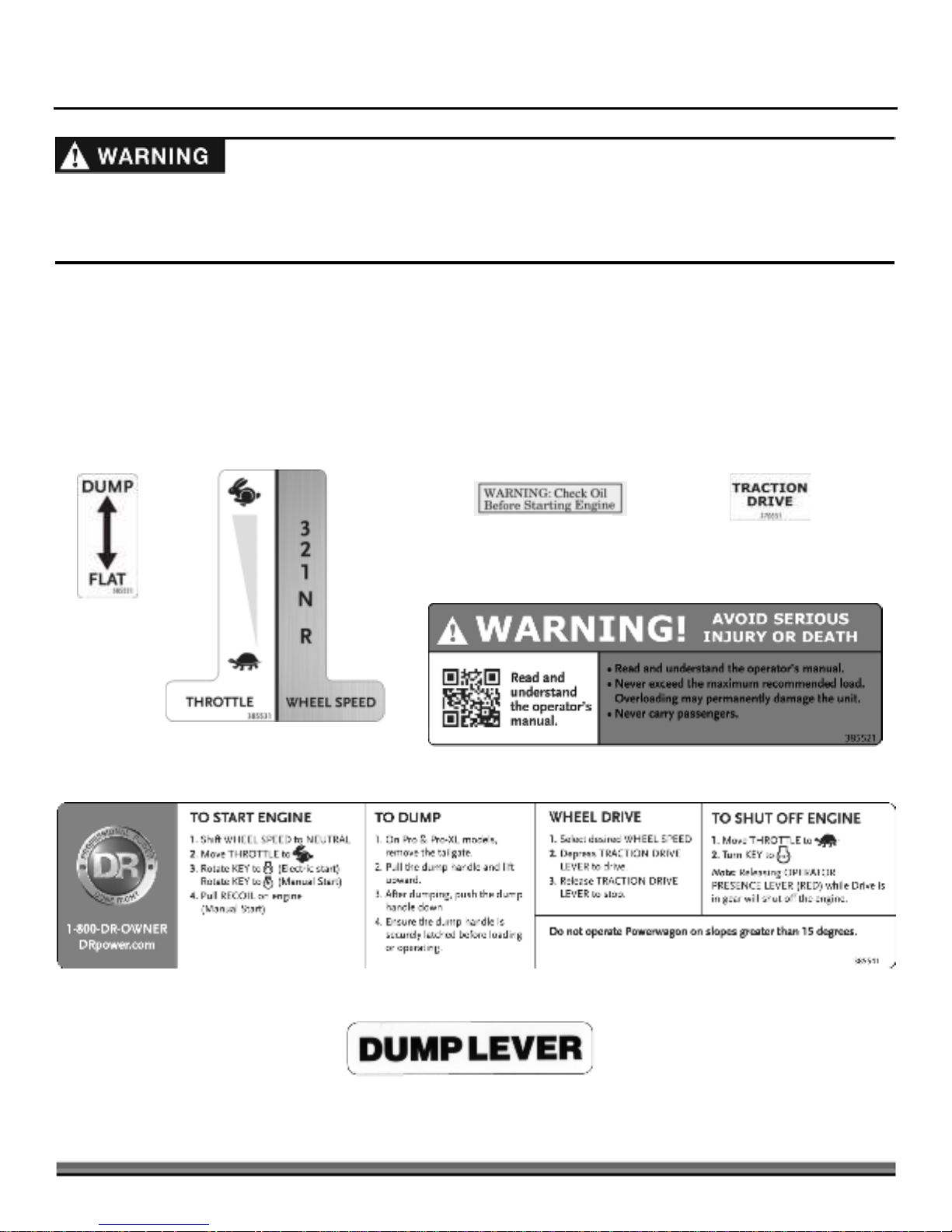
Your DR POWERWAGON carries prominent labels as reminders for its proper and safe use. Shown below are copies of all the
Safety and Information labels that appear on the equipment. Take a moment to study them and make a note of their location on
your POWERWAGON as you set up and before you operate the unit. Replace damaged or missing safety and information labels
immediately.
#38555
#38553
#13758
#37055
#38552
#38554
#15342
contact us at w w w.DRpow er.com 3
Page 4

Protecting Yourself and Those Around You
This is a high-powered machine, with moving parts operating with high energy at high speeds. Use proper clothing and safety
gear when operating this machine to prevent or minimize the risk of severe injury. You must operate the machine safely. Unsafe
operation can create a number of hazards for you. Always take the following precautions when operating this machine:
Wear shoes with non-slip treads when using your DR POWERWAGON. If you have safety shoes, we recommend wearing
them. Do not use the machine while barefoot or wearing open sandals.
Avoid wearing loose clothing or jewelry, which can catch on the machine’s moving parts.
Use ear protectors or ear plugs rated for at least 20 dba to protect your hearing.
Never allow people who are unfamiliar with these instructions to use the DR POWERWAGON. Allow only responsible
individuals who are familiar with these rules of safe operation to use your machine.
Never place your hands, feet, or any part of your body near or under any moving part while the machine is running.
To be safe, do not operate the machine near small children or pets, and never allow children to operate the DR
POWERWAGON.
The muffler and engine become very hot and can cause a severe burn; do not touch.
Never, under any conditions, remove, bend, cut, fit, weld, or otherwise alter standard parts on the DR POWERWAGON. This
includes all shields and guards. Modifications to your machine could cause personal injuries and will void your warranty.
Slope Operation
Slopes are a major factor related to slip and fall accidents, which can result in severe injury. All slopes require caution. If you feel
uneasy on a slope, do not use the DR POWERWAGON on it. Always take the following precautions when using this machine on
slopes:
Always:
Traverse up and down the face of slopes; never across. Exercise extreme caution when changing direction on slopes.
Watch for holes, ruts, or bumps in the landscape.
Use 1st gear on slopes with a maximum load of 800 lbs.
Never:
Operate near drop-offs, ditches, or embankments; you could lose your footing or balance.
Operate on slopes greater than 15 degrees, or any excessively steep slopes.
Operate on wet, or slippery slopes; reduced traction could result in slipping.
Park the DR POWERWAGON on a steep grade or slope.
Safety with Children and Pets
Tragic accidents can occur if the operator is not alert to the presence of children and pets. Children are often attracted to the
machine and the hauling activity. Never
Keep children out of the work area and under the watchful care of a responsible adult.
Be alert and always turn off the DR POWERWAGON engine if children or pets enter the work area.
Before, and while moving backwards, look behind, and down for small children and pets.
Never allow children to operate the DR POWERWAGON.
Use extra care when approaching blind corners, shrubs, trees, or other objects that may obscure your vision.
assume that children will remain where you last saw them.
4 DR
®
POWERWAGON
Page 5

Safety with Gasoline-Powered Machines
Gasoline is a highly flammable liquid. Gasoline also gives off flammable vapor that can be easily ignited and cause a fire or
explosion. Never overlook the hazards of gasoline. Always follow these precautions:
Never run the engine in an enclosed area or without proper ventilation as the exhaust from the engine contains carbon
monoxide, which is an odorless, tasteless, and deadly poisonous gas.
Store all fuel and oil in containers specifically designed and approved for this purpose and keep away from heat and open
flame, and out of the reach of children.
Fill the gasoline tank outdoors with the engine off and allow the engine to cool completely. Do not handle gasoline if you or
anyone nearby is smoking or if you are near anything that could cause it to ignite or explode. Replace the fuel tank and fuel
container caps securely.
If you spill gasoline, do not attempt to start the engine. Move the machine away from the area of the spill and avoid creating
any source of ignition until the gas vapors have dissipated. Wipe up any spilled fuel to prevent a fire hazard and properly
dispose of the waste.
Allow the engine to cool completely before storing the DR POWERWAGON in any enclosure. Never store the machine with
gas in the tank or a fuel container near an open flame or spark, such as a water heater.
Never make adjustments or repairs with the engine running. Disconnect the spark plug wire and keep the wire away from the
spark plug to prevent accidental starting.
Never check for an ignition spark with the spark plug or spark plug wire removed. Use an approved spark tester.
Never tamper with safety devices. Check their proper operation regularly.
Do not change the engine governor settings or modify the engine speed. Modifications will void your warranty.
To reduce fire hazard, keep the engine cooling fan and muffler area free of debris build-up such as leaves, grass, oil, grease or
any other combustible material.
Never operate the engine without the muffler. Inspect the muffler periodically and replace if necessary. If equipped with a
muffler deflector, inspect the deflector periodically and replace if necessary.
Never operate the engine with the air cleaner or cover over the carburetor air intake removed, except for adjustment. Removal
of such parts could create a fire hazard. Do not use flammable solutions to clean air filter.
Check fuel lines and fittings frequently for cracks or leaks, replace if necessary.
Replace rubber fuel lines and grommets when worn or damaged and after 5 years of use.
General Safety
The DR POWERWAGON must be operated safely to prevent or minimize the risk of minor or moderate injury. Unsafe operation
can create a number of hazards for you. Always take the following precautions when operating this machine:
Keep in mind that the operator or user is responsible for accidents or hazards occurring to other people, their property, and
themselves.
Your DR POWERWAGON is not a plaything. Exercise extreme caution at all times. The design of this machine is to haul
material. Do not use it for any other purpose.
Give complete and undivided attention to the job at hand. Before you use your new machine, be sure you know how to
engage the parking brake and stop the DR POWERWAGON at a moment's notice.
Always operate the DR POWERWAGON from behind the handlebars, never from the side.
Never use the DR POWERWAGON to drag or tow items.
Do not overload the DR POWERWAGON. Be careful of top-heavy loads. The higher the load, the more chance of tipping over
the machine. Loads may shift during operation; to be safe, secure your loads and even them out when possible. The
maximum load is 500 lbs. (Premier), 700 lbs. (Pro) and 800 lbs. (Pro-XL).
Use 1st gear with loads over 300 lbs. And on slopes. Excessive speed can be dangerous. Operate the machine in the lowest
gear that is satisfactory to do the job.
contact us at w w w.DRpow er.com 5
Page 6

General Safety (Continued)
Use caution when moving downhill and braking. Apply the parking brake slowly to avoid tipping forward.
When shifting to reverse, be careful to avoid tipping as the swivel wheel changes direction.
Watch for traffic when operating near roadways.
Never allow people or pets to ride in the DR POWERWAGON.
If the machine should start making an unusual noise or vibration, stop the engine and wait five (5) minutes to cool. Vibration
is generally a warning of trouble. Disconnect the spark plug wire and inspect for damaged parts. Clean and repair and/or
replace damaged parts.
Built-in safety features, such as the operator presence system, are effective only when maintained and kept in place.
Always keep the equipment in a good safe operating condition. Always make certain nuts and bolts are tight and always use
the supplied self-locking hardware; do not substitute. Use only approved DR parts.
Use the DR POWERWAGON only in daylight.
While using the machine, do not hurry or take things for granted. When in doubt about the equipment or your surroundings,
stop the machine and take the time to look things over. Make sure that you have 100% control of the machine at all times.
Never leave the DR POWERWAGON unattended with the engine running.
Do not operate the machine when under the influence of alcohol, drugs, or medication.
See manufacturer’s instructions for proper operation and installation of accessories. Only use accessories approved by DR
Power Equipment.
California Proposition 65
California Proposition 65:
Engine exhaust and some of its constituents are known to the state of California to cause cancer, birth defects, and other
reproductive harm.
This product contains or emits chemicals known to the state of California to cause cancer, birth defects, and other
reproductive harm.
A Note to All Users
Under California law, and the laws of some other states, you are not permitted to operate an internal combustion engine using
hydrocarbon fuels without an engine spark arrester. This also applies to operation on US Forest Lands. All DR®
POWERWAGONS shipped to California, New Mexico and Washington State are provided with spark arresters. Failure of the
owner or operator to maintain this equipment in compliance with state regulations is a misdemeanor under California law and
may be in violation of other state and/or federal regulations. Contact your State Park Association or the appropriate state
organization for specific information in your area.
No list of warnings and cautions can be all-inclusive. If situations occur that are not covered by this manual, the operator must
apply common sense and operate this DR
DR-OWNER (376-9637) for assistance.
®
POWERWAGON in a safe manner. Contact us at www.DRpower.com or call 1-800-
Additional Information and Potential Changes
Country Home Products, Inc. reserves the right to discontinue, change, and improve its products at any time without notice or
obligation to the purchaser. The descriptions and specifications contained in this manual were in effect at printing. Equipment
described within this manual may be optional. Some illustrations may not be applicable to your machine.
6 DR
®
POWERWAGON
Page 7
`Chapter 2: Setting Up The DR POWERWAGON
A
All
A
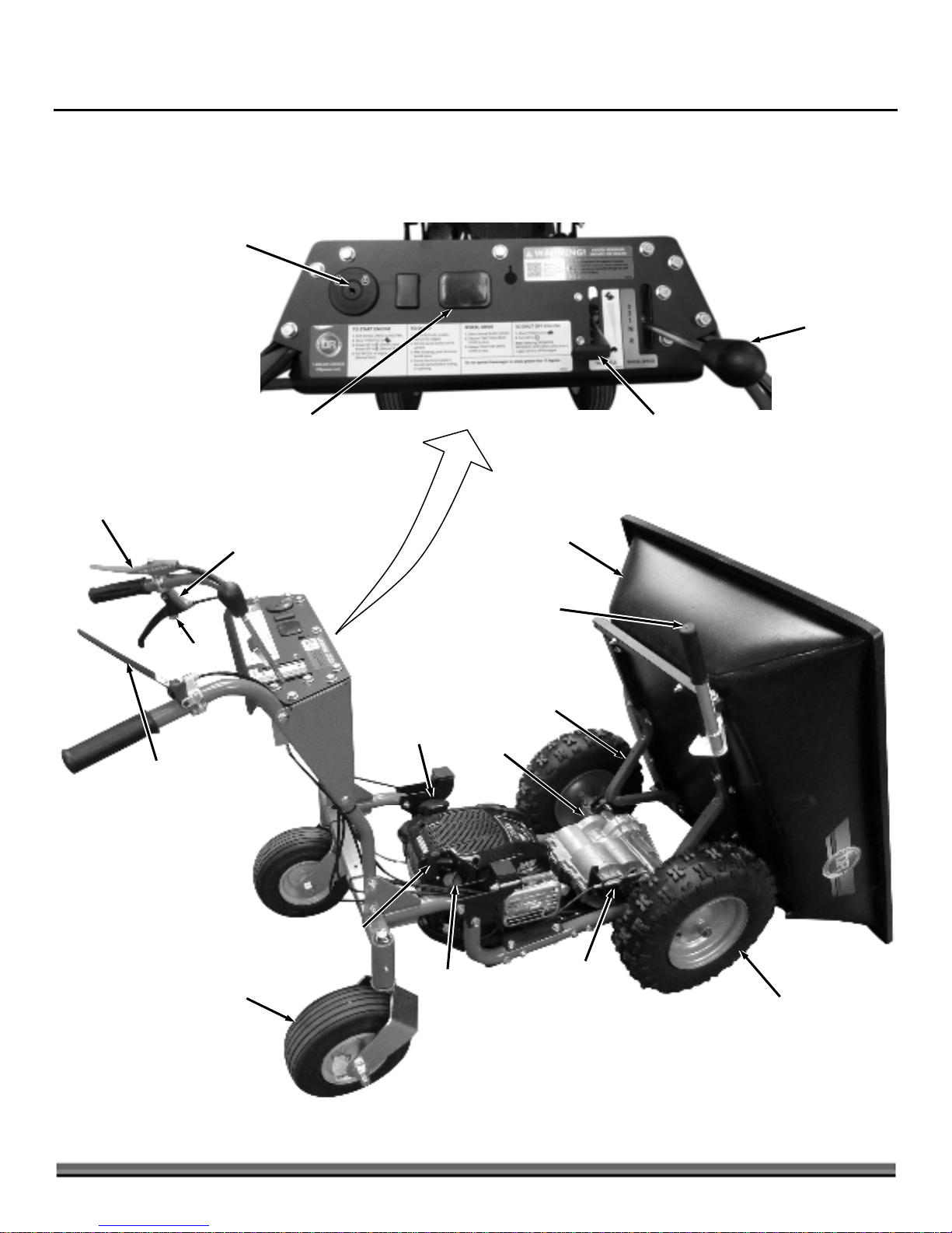
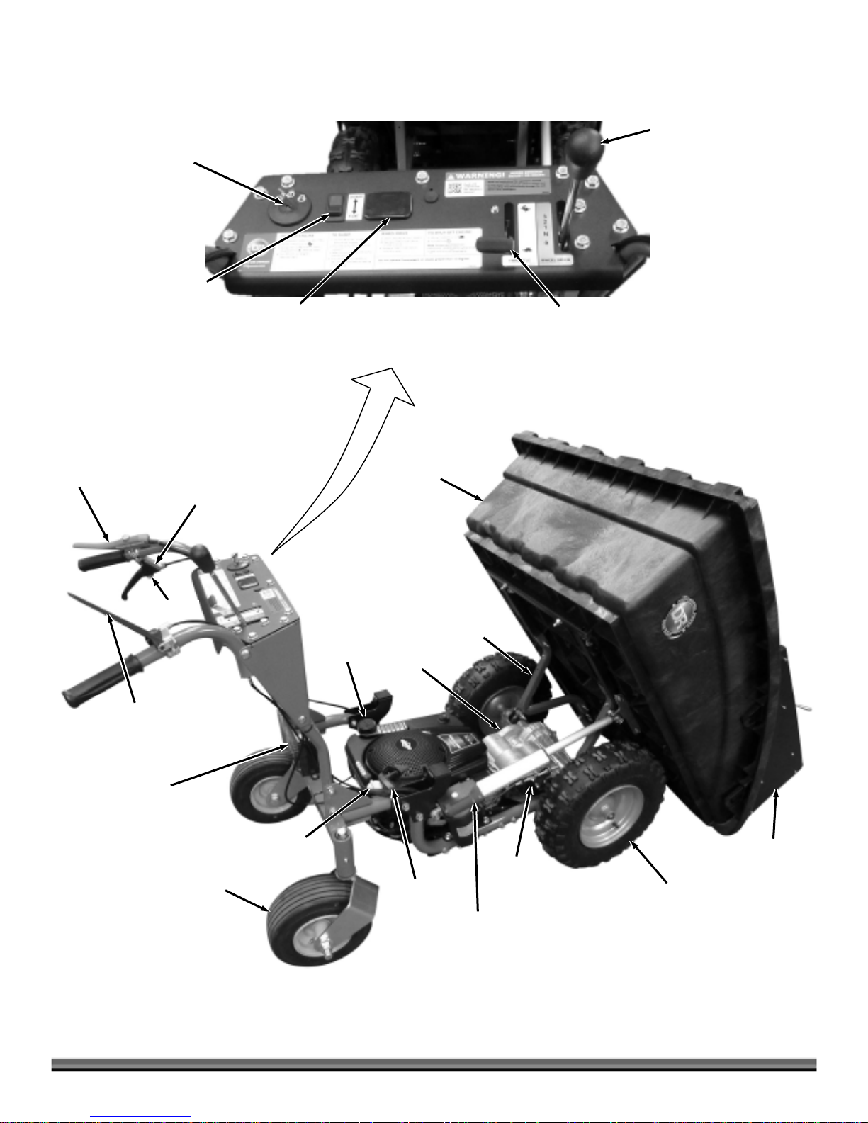
It may be helpful to familiarize yourself with the controls and features of your DR POWERWAGON as shown in Figure 2 before
beginning these procedures. If you have any questions at all, please feel free to contact us at www.DRpower.com.
DR PREMIER POWERWAGON Controls and Features
Key Switch
Shift Lever
Operator Presence
Lever
Brake Lock
Traction Drive
Lever
Maintenance Meter
Location
(Optional Accessory)
Brake Lever
Throttle
Control
Premier Bed
ssembly
Dump Handle
(Premier and Pro
Standard)
Dump Arm
Fuel Cap
Transaxle
Manual Recoil
Starter Handle
Caster Wheels
Oil Fill
Figure 2a
Brake Pad
ssembly
-Terrain Tires
contact us at w w w.DRpow er.com 7
Page 8
DR PRO and PRO-XL POWERWAGON Controls and Features
A
All
A
Key Switch
Electric Dump Switch
(Pro Optional)
(Pro-XL Standard)
Maintenance Meter
Location
(Optional Accessory)
Shift Lever
Throttle
Control
Operator Presence
Lever
Brake Lock
Traction Drive
Lever
Battery
(Electric-starting
model only)
Caster Wheels
Brake Lever
Oil Fill
Fuel Cap
Pro and
Pro-XL Bed
Transaxle
Manual Recoil
Starter Handle
Dump Arm
Brake Pad
ssembly
ctuator
(Pro Optional)
(Pro-XL Standard)
Sidewall and
Tailgate
-Terrain Tires
8 DR
®
POWERWAGON
Figure 2b
Page 9

Specifications
PREMIER PRO PRO-XL
Engine
BATTERY
BED
Capacity - Volume (Cu Ft) 5.2 8 8
Capacity - Weight (Lbs) 500 700 800
Bed Height (In) 20 20 20
Construction High-Density Polyethlene
Dump Angle (Degrees) 60° 60° 60°
Latch Mechism Intergrated Latch & Handle Intergrated Latch & Handle N/A (Actuator Latches The
TRANSMISSION
Speeds Forward 3: 3.7 Mphmmnm
Briggs & Stratton
(See Engine Owner’s Manual
for Engine Specifications)
Briggs & Stratton
(See Engine Owner’s Manual
for Engine Specifications)
Briggs & Stratton
(See Engine Owner’s Manual
for Engine Specifications)
N/A 12V, 9 Ah 12V, 9 Ah
(Hdpe)
Cellular Core High Strength
Molded Polyethylene
Cellular Core High Strength
Molded Polyethylene
Bed)
Forward 3: 3.7 Mph
Forward 2: 2.4 Mph
Forward 1: 1.3 Mph
Reverse: 1.4 Mph
Forward 2: 2.4 Mph
Forward 1: 1.3 Mph
Reverse: 1.4 Mph
Forward 3: 3.7 Mph
Forward 2: 2.4 Mph
Forward 1: 1.3 Mph
Reverse: 1.4 Mph
Brake Transaxle Disc Brake Transaxle Disc Brake Transaxle Disc Brake
FRAME
Frame Type Tubular Steel (1.5" Diameter
X 12 Ga Thick)
Tubular Steel (1.5" Diameter
X 12 Ga Thick)
Tubular Steel (1.5" Diameter X
12 Ga Thick)
Skid Plate 9 Ga Thick 9 Ga Thick 9 Ga Thick
Handlebar Height (In) 37 37 37
ACTUATOR
Included N/A N/A Yes
Full Load Speed
N/A N/A 12 (0.47)
(Mm/S (In/S))
Full Load Seconds/Lift N/A N/A 16.745
No Load Speed
N/A N/A 20 (0.79)
(Mm/S (In/S))
No Load Seconds/Lift N/A N/A 9.962
Stroke (Mm (In)) N/A N/A 200 (7.87)
Duty Cycle N/A N/A 10%
(Approximately 1 Full Capacity
Load Every 4.5 Minutes)
Enclosure Rating N/A N/A IP65
WHEELS
Front (Size & Type) 16" Diameter, 4" Width,
Snowhog Tread
16" Diameter, 4" Width,
Snowhog Tread
16" Diameter, 4" Width,
Snowhog Tread
Rear (Size & Type) 11" Diameter, 4" Width, Rib 11" Diameter, 4" Width, Rib 11" Diameter, 4" Width, Rib
DIMENSIONS
Overall Product Dim's 66.5 L X 33.25 W X 41 H 63.25 L X 34.5 W X 41 H 63.25 L X 34.5 W X 41 H
Product Weight 184 231 240
Ground Clearance 2" 2" 2"
contact us at w w w.DRpow er.com 9
Page 10
g
A
6
1
6
Assembling the DR POWERWAGON
2
4
Figure 4
5
8
Figure 5
Bolts and
Locknuts
Tools & Supplies Needed:
5
Two 9/16" Wrenches
1/2" Wrench
1/2" Socket with Ratchet and Extension
Two 3/4" Wrenches
10" Adjustable Wrench
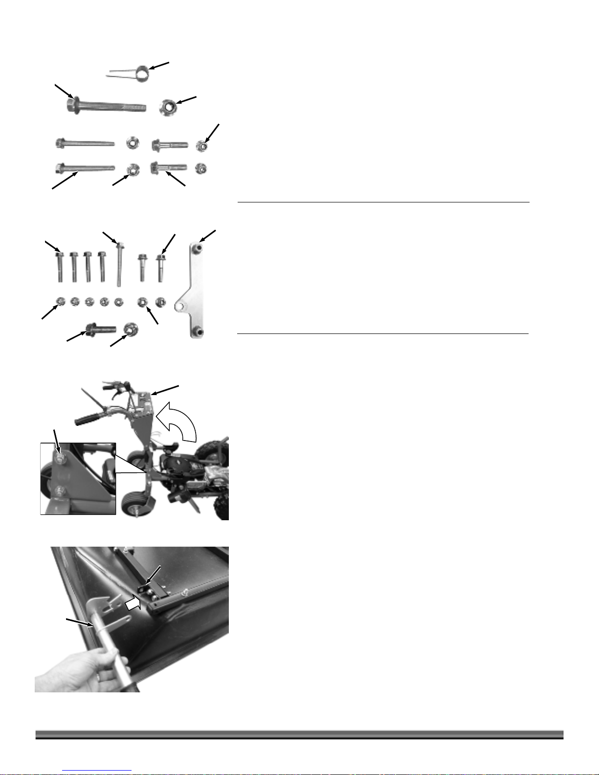
Parts Supplied in Product Package - PREMIER AND PRO MODELS (Figure 4
and list below):
7
4
7
2
3
3
Handlebar
ssembly
Item # Part # Description Qty
1 ........... 38540 ....... Spring, Torsion, 360 Deg, .063" Wire, .798" OD ... 1
2 ........... 33353 ....... Bolt, Hex, Flange, 1/2-13 X 4", GR5 ....................... 1
1
3 ........... 38596 ....... Bolt, Hex, Flange, 3/8-16 X 1-3/4", GR5, ZP .......... 2
4 ........... 38598 ....... Bolt, Hex, Flange, 5/16-18 X 2-1/2", GR8, ZP ........ 2*
5 ........... 33335 ....... Nut, Nylon Lock, Flanged, 1/2-13 ........................... 1
6 ........... 33333 ....... Nut, Nylon Lock, Flanged, 3/8-16 ........................... 2
7 ........... 33332 ....... Nut, Nylon Lock, Flanged, 5/16-18 ......................... 2*
*Pro Model has Quantity of 4 for these items.
Parts Supplied in Product Package – PRO-XL MODEL (Figure 5 and list below):
Item # Part # Description Qty
1 ........... 37936 ....... Bracket, Actuator, Dump Arm ................................ 1
2 ........... 39084 ....... Bolt, Hex, Flange, 1/2-13 X 1-1/2", GR5, ZP .......... 1
3 ........... 38596 ....... Bolt, Hex, Flange, 3/8-16 X 1-3/4", GR5, ZP .......... 2
4 ........... 39085 ....... Bolt, Hex, Flange, 5/16-18 X 3", GR8, ZP ............... 1
5 ........... 38598 ....... Bolt, Hex, Flange, 5/16-18 X 2-1/2", GR8, ZP ........ 4
6 ........... 33335 ....... Nut, Nylon Lock, Flanged, 1/2-13 ........................... 1
7 ........... 33333 ....... Nut, Nylon Lock, Flanged, 3/8-16 ........................... 2
8 ........... 33332 ....... Nut, Nylon Lock, Flanged, 5/16-18 ......................... 5
Compare the contents of the Product Package with the “Parts Supplied in
Product Package” list above. If you have any questions please contact us at
www.DRpower.com or call 1-800-DR-OWNER (376-9637) for assistance.
Figure 6
Dump
Handle
Figure 7
10 DR
®
POWERWAGON
Dump Handle
Mountin
Bracket
1. Lift the Handlebars to the operating position and install a 3/8-16 X 1-3/4
Flange Bolt and Locknut on each side using two 9/16" Wrenches (Figure 6).
Note: Ensure that the top Handlebar Bolts are installed in the same direction as
the lower Bolts with the heads on the inside of the Handlebars.
2. Tighten the lower Handlebar Bolts that were already in place.
Premier Bed - Assembly and Installation
If you have the Pro or Pro-Xl Model, refer to the next section “Pro and Pro-XL
Bed - Assembly and Installation”.
If you are installing the Flatbed on your POWERWAGON, proceed to the
“Flatbed Installation” section in this Chapter.
1. Position the Dump Handle at the right rear corner of the Bed where the
Mounting Bracket is located (Figure 7).
Page 11
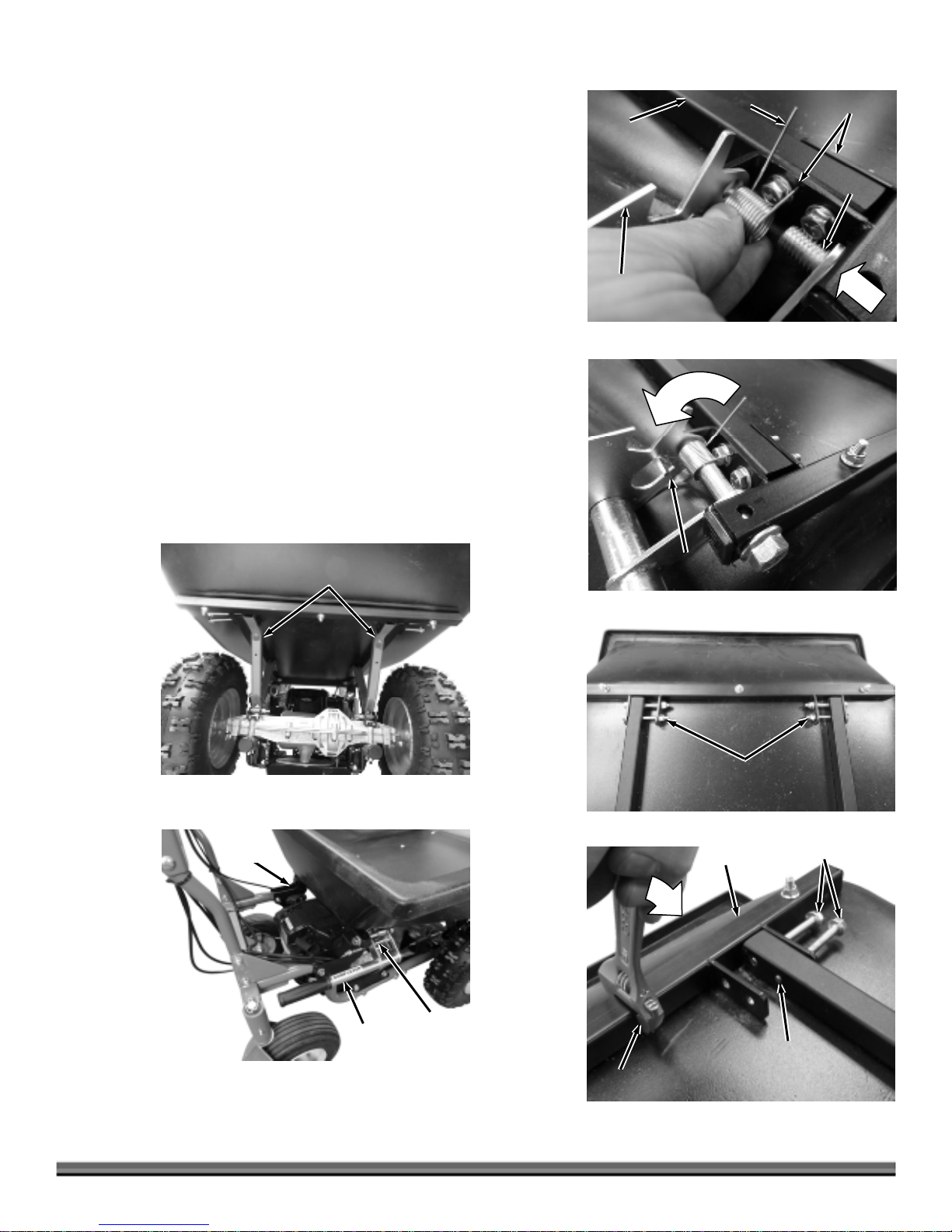
2. Insert one end of the Torsion Spring into the small hole in the Frame
A
A
r
(positioned as shown) and push it through to the hole on the other side of
the Frame Tube (Figure 8).
3. Install the 1/2-13 X 4" Flange Bolt through the Frame, Spring and Dump
Lever. Secure with the 1/2-13 Locknut using two 3/4" Wrenches. Do not
over tighten.
4. Rotate the remaining end of the Spring and secure it under the Spring Tab
(Figure 9).
5. Remove the Locknuts from the front of the Bed Frame and use a 1/2"
Wrench to turn the Front Bed Bolts out so the end of the threads are flush
with the inside of the Frame opening (Figures 10 and 11).
Note: To ease the process of aligning the ends of the Bolts, a 10" Adjustable Wrench
can be used on the Frame Tube to align the holes.
6. Place the Bed on the Power Wagon with the Dump Arms inside the Frame at
the front of the Bed Assembly (Figures 12).
7. Ensure the back of the Bed Assembly is on the Bed Rest Brackets and the
Dump Lever is fully latched onto the Latch Pin (Figure 13).
Frame
Tube
Dump
Leve
Figure 8
Spring
Holes
Bolt
Figure 12
Bed Rest
Bracket
Dump
rms
Bed
Figure 9
Figure 10
Spring
Tab
Locknuts
Tube
Front Bed Bolts
Figure 13
Dump
Handle
Latch
Pin
Even With
djustable
Wrench
Figure 11
contact us at w w w.DRpow er.com 11
Tube (Flush)
Page 12

A
A
r
A
A
A
A
Rear Bed
Support
Bolt
Dump
rms
Front Bed
Bolts
8. Turn the Front Bed Bolts through the Frame and Dump Arms at the front of
the Bed with a 1/2" Socket and Ratchet with Extension (Figure 14).
Note: If the Bolts are not aligning well with the holes in the Frame and Dump Arms,
a 10" Adjustable Wrench can be used on the front Frame Tube to align the holes
(Figure 15).
9. Secure the Front Bed Bolts to the Frame and Bed Supports with the four
5/16-18 Locknuts (you removed in step 5) using a 1/2" Wrench and 1/2"
Socket.
10. Secure the rear of the Dump Arms to the Frame with two 5/16-18 X 2-1/2"
Flange Bolts and Locknuts using a 1/2" Wrench and Socket (Figure 14).
Figure 14
Figure 15
Figure 16
Dump
rms
Frame
Tube
Bed
ssembly
Your Premier POWERWAGON assembly is complete. Proceed to the “Check the
Tire Pressure” section in this Chapter to continue with the setup of your
machine.
Pro and Pro-XL Bed - Assembly and Installation
If you are installing the Flatbed on your POWERWAGON, proceed to the
“Flatbed Installation” section in this Chapter.
PRO MODEL WITH HAND DUMP
1. Installing the Dump Handle on the Pro Model is the same as the Premier
Model. Refer to Steps 1 through 4 of “Premier Bed - Assembly and
Installation” if you do not have the Actuator Dump option.
PRO and PRO-XL MODELS
1. Place the Bed Assembly at the front of the machine with the Tailgate end
resting on the ground (Figure 16).
2. Move the Bed Assembly onto the Dump Arms and rotate the Bed back and
onto the Dump Arms.
PRO MODEL WITH HAND DUMP
1. Secure the Bed Frame to the Dump Arms with four 5/16-18 X 2-1/2" Flange
Bolts and Locknuts using a 1/2" Wrench and 1/2" Socket with Ratchet and
Extension (Figure 17).
PRO-XL MODEL ACTUATOR DUMP
1. For the following steps the Actuator Bracket must be positioned on the right
hand side of the Frame with the mounting hole towards the Actuator (Figure
18).
5/16-18 X 2-1/2" Flange
Bolts and Locknuts
Dump
rm
Figure 17
12 DR
®
POWERWAGON
ctuator
Bracket
ctuato
Mounting Hole
(Facing Actuator)
Figure 18
Page 13
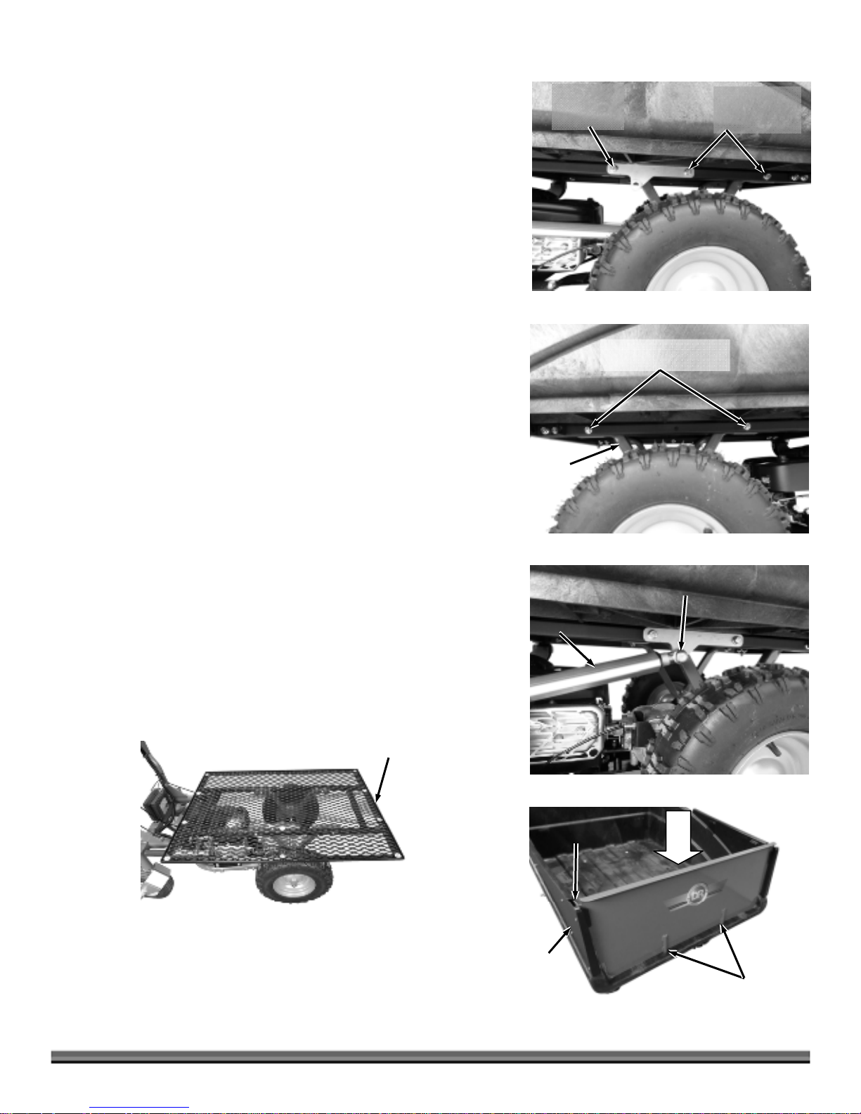
2. Secure the rear of the Actuator Bracket to the Frame and Dump Arm with a
A
r
A
5/16-18 X 3" Flange Bolt and Locknut using a 1/2" Wrench and 1/2" Socket
with Ratchet and Extension (Figure 19).
3. Secure the front of the Actuator Bracket with a 5/16-18 X 2-1/2" Flange Bolt
using a 1/2" Wrench and 1/2" Socket with Ratchet and Extension.
4. Secure the front/right (Figure 19) and both left side locations (Figure 20) of
the Bed Frame to the Bed Supports with three 5/16-18 X 2-1/2" Flange Bolts
and Locknuts using a 1/2" Wrench and 1/2" Socket with Ratchet and
Extension.
5. Remove the Plastic Protectors (if present) from the end of the actuator
(Figure 21).
6. Secure the end of the Actuator to the Actuator Bracket with a 1/2-13 X 1-1/2"
Flange Bolt and Locknut using two 3/4" Wrenches.
BOTH MODELS
1. Install the Tail Gate onto the front of the Bed Assembly (Figure 22).
Note: Ensure that the Guide Pins are fully into the Bed and that the Tabs at both
sides are locked into the Side Walls.
5/16-18 X 3"
Flange Bolt
and Locknut
Figure 19
5/16-18 X 2-1/2"
Flange Bolt and
Locknut
5/16-18 X 2-1/2" Flange
Bolts and Locknuts
Flatbed Installation (Figure 23)
1. Installing the Dump Handle on the Flatbed is the same as the Premier
Model. Refer to Steps 1 through 4 of “Premier Bed - Assembly and
Installation”. See “PRO MODEL WITH HAND DUMP” to secure the
Flatbed to the Dump Arms.
2. Installing the Actuator Bracket and attaching the Actuator to the Flatbed is
the same procedures as the “Pro-XL Model Actuator Dump”. Refer to Steps
1 through 6 of “Pro-XL Model Actuator Dump”.
Flatbed
Dump
rm
Figure 20
1/2-13 X 1-1/2" Flange Bolt
and Locknut
ctuato
Figure 21
Tab
Figure 23
Tailgate
Side
Wall
Figure 22
contact us at w w w.DRpow er.com 13
Guide Pins
Page 14

Check the Tire Pressure
Tools Needed:
Tire Pressure Gauge
Air Compressor
Do not over inflate the tires. Inflate to the manufacturers recommended
pressure found on the tires.
Valve Stem
Protective
Cap
Figure 24
1. Remove the Valve Stem Protective Cap and check the tire pressure with a tire
pressure gauge (Figure 24).
2. If the pressure is too low, add air through the Valve Stem with an air hose.
3. Replace the Valve Stem Protective Cap when finished.
Note: The heavier the load, the higher the tire pressure should be. Do not go above
the maximum recommended load or pressure.
Adding Oil and Gasoline
Engine Oil Capacity: Refer to the Engine Owner’s manual for Engine capacities and specifications.
You must add oil before starting the engine. This machine is shipped without oil. Traces of oil may be in the reservoir from
factory testing, but you must add oil before starting the engine
. Fill the reservoir slowly, checking the dipstick frequently to avoid
overfilling.
To get an accurate reading when checking the oil level:
The machine should be on a level surface.
The dipstick should be screwed down
Tip: To avoid confusion, we recommend leaving the Caps on the Fuel and Oil Fills until you are ready to pour either gasoline or
oil into the correct Fill.
Note: Use only SAE 30 High Detergent oil. Other types of oil could cause problems operating your machine. Please refer to your Engine
Owner’s Manual for detailed oil information. You must lift the Bed to access the Oil and Fuel Reservoirs.
Gas Fill
Cap
Dipstick/Oil Fill
on Briggs & Stratton engines.
1. Place the machine on a level surface and lift the Bed to the fully up position
(Figure 25).
2. Remove the Oil Dipstick/Fill Cap.
3. Initially add 14 oz. of SAE 30 High Detergent oil recommended by the
Engine Manufacturer and wait one minute for the oil to settle.
4. Check the level on the Dipstick and continue adding a few ounces of oil at a
time, rechecking the Dipstick until the oil reaches the fill mark. Be careful
not to overfill.
5. Fill the Fuel Tank to not more than 1/4" from the bottom of the Fill Neck
with fresh, unleaded gas. See the Engine
for more information.
Manufacturer’s Owner’s Manual
Figure 25
14 DR
®
POWERWAGON
Page 15

Connect the Battery Wires (Electric Start Models)
1. Remove any protective Caps that may be on the Battery Terminals from
shipping.
2. Connect the red wire to the red Terminal and connect the black wire to the
black Terminal (Figure 26).
Red
Wire/Terminal
Black
Wire/Terminal
Battery
Figure 26
contact us at w w w.DRpow er.com 15
Page 16

16 DR
®
POWERWAGON
Page 17

Chapter 3: Operating The DR POWERWAGON
It may be helpful to better familiarize yourself with the features of your DR
POWERWAGON by reviewing Figure 2 in Chapter 2 before beginning the steps
outlined in this chapter.
Before Starting the Engine
1. Check the oil level every time
2. Check the gas level (Figure 25 on page 14).
3. Check the tires for proper inflation (Figure 24 on page 14).
4. Make sure the Dump Latch is secured (Premier and Pro Models) (Figure 2a
on page 7).
5. Set the Parking Brake by squeezing the Brake Lever on the right Handlebar
and lift up on the Parking Brake Lock, locking the Lever in place (Figure 27).
Note:
The DR POWERWAGON is equipped with an Operator Presence Control for
added safety. The Operator Presence Lever must be depressed whenever the Shift
Lever is in gear, or the Engine will stop
the Operator Presence Lever (Figure 27) only if the Shift Lever is in the "N"
(Neutral) position (Figure 28).
you use the machine (Figure 25 on page 14).
.
You may run the Engine without depressing
Electric Starting
Operator
Presence Lever
Figure 27
Key Switch
Figure 28
Parking
Brake Lock
Brake Lever
Shift
Lever
Throttle Control
1. Move the Shift Lever to the NEUTRAL N position (Figure 28).
2. Move the Throttle Lever to the FAST position.
3. Turn the Key to the START
position. As soon as the Engine starts,
release the Key, and it will return to the RUN
position.
Recoil
Handle
Manual Recoil Starting
Manual recoil starting can be used for both Electric-Starting and Manual-
Note:
Starting models.
1. Move the Shift Lever to the NEUTRAL N position (Figure 28).
2. Move the Throttle Lever to the FAST
3. Turn the Key to the RUN
position.
position.
4. Pull the Recoil Handle slowly, until you feel resistance; then pull the Handle with a rapid, full arm stroke to overcome
compression and start the Engine (Figure 29). Repeat if necessary.
Figure 29
contact us at w w w.DRpow er.com 17
Page 18

Operating
Operator
Presence Lever
Figure 30
Key Switch
Figure 31
Brake Lever
Shift Lever
Throttle
Control
The DR POWERWAGON has a three-speed forward transmission and singlespeed reverse. Use the lower gears for slower speeds, heavy loads, or more
power, and the higher gears for transport over smooth terrain. Use 1
st
gear with
loads over 300 lbs and on slopes. Never use your machine on slopes greater
than 15.
1. After the Engine is started, release the Parking Brake by squeezing and
releasing the Brake Lever (Figure 30).
2. Hold down the Operator Presence Lever.
3. Move the Shift Lever to the desired gear (Figure 31).
Always release the Traction Drive Lever when shifting to avoid damaging the
gears.
4. Squeeze the Traction Drive Lever on the right side Handlebar slowly
until the
machine moves in the desired direction (Figure 32).
Squeezing the throttle fast will make the DR POWERWAGON "jump" into
motion. Squeeze the throttle slowly and ease the machine into gear.
When engaging reverse, use extra caution. Check your path and footing
before engaging the clutch.
Figure 32
Operator
Presence Lever
Figure 33
18 DR
Brake Lever
®
POWERWAGON
Traction Drive
Lever
Parking
Brake Lock
Stopping
1. Release the Traction Drive Lever (Figure 32).
2. Shift to the NEUTRAL N position (Figure 31).
3. Release the Operator Presence Lever (Figure 33).
4. Set the Parking Brake by squeezing the Parking Brake Lever on the left side
Handlebar and lifting the Parking Brake Lock.
5. Move the Throttle Control Lever to the SLOW
6. Turn the Key to the STOP
position and remove it for safety.
position (Figure 31).
In an emergency situation, releasing the operator presence lever will stop the
machine. After the machine stops, follow steps 1, 2 and 4 thru 6 above).
Always set the parking brake when your machine is stopped.
Operating Tips
Avoid abrupt start-ups. Always squeeze the throttle slowly to avoid bucking,
or tipping the DR POWERWAGON.
When using reverse, check to see that there are no obstacles behind you.
Practice backing up in an open area with no load in the DR POWERWAGON.
Page 19

Loading
The recommended maximum load limit for the DR POWERWAGON is 500 lbs (Premier), 700 lbs (Pro) or 800 lbs (Pro-XL).
Never operate on slopes greater than 15°. Placing more weight in the bed may be dangerous to the operator and can
permanently damage the unit.
Be careful when transporting heavy loads with your DR POWERWAGON. If the brake is applied suddenly, the load may shift
and the wagon may start to tip forward. Brake slowly and try to avoid overloading the wagon.
When loading your DR POWERWAGON keep in mind the bulk and weight of what you will be hauling and the terrain you will
be crossing.
Keep the load balanced and secured. Always distribute the load evenly so your DR POWERWAGON will be as stable as
possible.
Do not pile material too high. Divide your load and make several lighter trips. Do not pile heavy loads, such as rocks or
gravel, to a height that will make the DR POWERWAGON top-heavy and susceptible to tipping over.
Be careful going downhill and applying the brake. Shift into 1
to avoid dumping the load.
st
gear before going down a slope. Squeeze the brake very slowly
Slopes and Uneven Terrain
When operating over uneven terrain and slopes, use extreme caution to ensure solid and firm footing. Move slowly if the ground
is rough, especially with a full load. Use 1st gear on slopes. Never operate on slopes greater than 15°.
Never operate the DR POWERWAGON on slopes greater than 15 degrees
(Figure 34). This is for safety and proper Engine operation. Doing so could
deprive the Engine of oil and cause it to overheat resulting in component
damage.
USE CAUTION: The DR POWERWAGON may become unstable when
moving over ruts, bumps, and other depressions.
When going down a slope, shift into 1
shift in the middle of a slope. Find as level a spot as possible and set the
parking brake before shifting.
st
gear before starting down. Never
On a slope, a heavy load will tend to shift. When using your DR
POWERWAGON, keep in mind that loads tend to shift to the downhill side of
the body. Secure your load in the Bed to limit the shifting of the load on
slopes. The higher and heavier the load, the greater the chance of tipping
over the DR POWERWAGON. Travel up and down slopes. Avoid going
across slopes.
Again, be especially careful with full loads. A good rule of thumb: the steeper
the hill, the lighter and lower your load should be.
When going downhill, keep a firm grip on the Handlebars and push down
slightly. Do not apply the Parking Brake abruptly when going downhill with a
heavy load or the DR POWERWAGON may pitch forward onto its front end.
15° Max.
Figure 34
contact us at w w w.DRpow er.com 19
Page 20

Tailgate
Figure 35
Latch
Unloading the Bed
Dumping – Manually
Note: For safety reasons, the DR POWERWAGON Bed is designed NOT to dump
automatically once you release the Dump Lever. You must pull the Dump Handle
up to lift the back of the Bed to cause it to tip forward.
1. Shift the machine to Neutral and set the Parking Bake.
2. Remove the Tailgate (Pro Model only) (Figure 35).
3. Stand at the right rear of the Bed.
4. Pull up on the Handle of the Dump Lever to dump the load (Figure 36).
5. After unloading, push the Bed back down into place by hand. Be sure the
Dump Lever latches securely.
Note: The Bed of the DR POWERWAGON is balanced so you can dump the load
with minimal effort. If you are carrying a very heavy load, you may not be able to lift
the Bed to dump it when you release the Latch Lever. In this case, you will need to
manually remove part of the load from the back of the Bed, until the load is light
enough to allow the Bed to tip forward when you lift up on the back of it.
Dump
Lever
Figure 36
Key Switch
Electric Dump System – Pro-XL Model
The Electric Dump System brings new conveniences to the function of your DR
POWERWAGON. We have included some operating hints and precautions.
Please review them carefully.
Operating the Electric Dump
1. Shift the machine to Neutral and set the Parking Brake.
Electric Dump Switch
Figure 37
2. Remove the Tailgate.
3. If the Engine is Off, turn the Key to the RUN
position.
4. Hold the Electric Dump Switch in the upper “DUMP” position, to raise the
Bed to empty it (Figure 37).
5. Hold Power Dump Switch down in the lower “FLAT” position, to lower the
Bed.
Operating Hints
The Electric Dump System allows the Bed to be stopped and positioned anywhere in the tipping range. Emptying loose
material and depositing solid loads in a more precise way.
The Electric Dump System also makes it possible to distribute loose materials over an area rather than in a concentrated pile
for distribution later. With the Bed partially tipped, you can move your DR POWERWAGON in reverse while the material flows
from the front of the Bed. This is especially helpful in road maintenance and similar work.
Make certain you are familiar with the terrain where you intend to work and anticipate the effect that load changes in the Dump
Bed might have upon operating factors. Review your Safety
&
Operating Instructions Manual carefully for safe procedures.
20 DR
®
POWERWAGON
Page 21

Chapter 4: Maintaining The DR POWERWAGON
P
Regular maintenance is the way to ensure the best performance and long life of your machine. Please refer to this manual and the
engine manufacturer's owner's manual for maintenance procedures. Service intervals listed in the checklist below supersede
those listed in the engine manufacturer's owner's manual.
When performing any maintenance, you must first shut off the engine, set the parking brake, wait five minutes to allow parts to
cool and disconnect the spark plug wire, keeping it away from the spark plug.
Regular Maintenance Checklist
ROCEDURE BEFORE EACH USE EVERY 25 HOURS EVERY 100 HOURS
Check Operator Presence Lever
Check Engine Oil Level
Check General Equipment Condition
Check Tire Pressure
Lubricate Caster Wheel Grease Fittings
Clean Air Filter & Pre-cleaner
Change Engine Oil (8.75 Engines Only) 1st time 5 hours
Check Parking Brake Adjustment
Check Belt Tension & Condition
Check Cable Connections
Clean Engine Exterior & Cooling Fins
Replace Spark Plug
Replace Air Filter & Pre-cleaner
Battery Care (For Electric-Starting models)
Proper care can extend the life of a Battery. Follow these recommendations to ensure your Battery’s best performance and long
life:
Do not allow the Battery charge to get too low. If the machine is not used, charge the Battery every 4 – 6 weeks. Operate the
Engine for at least 45 minutes to maintain proper Battery charge.
Store an unused Battery in a dry area that does not freeze.
Do not charge an already charged Battery. In theory, you cannot overcharge our Battery with a trickle charger; however, when a
Battery is fully charged and the charger is still on, it generates heat that could be harmful to the Battery. A fully charged Battery
will read 12V-13.2V with a voltmeter.
Do not continue to crank the Engine when the Battery charge is low.
Under normal work conditions, the Battery will not need special attention with the addition of the Electric Dump System. If you
are operating for extended periods with frequent dumps, it might be best to leave the Engine running during stand still periods
to maintain proper charge levels.
Charging the Battery
Operate the engine for at least 45 minutes to maintain proper battery charge. If the battery loses its charge, you will need to use a
trickle charger (like the DR Battery Charger) to recharge it. The charger should have an output of 12 volts at no more than 2 amps.
At 1 amp, the Battery may need charging for as long as 48 hours.
At 2 amps, the Battery may need charging for as long as 24 hours.
Note: Using the Recoil Starter and then running the Engine will not recharge a dead or significantly discharged Battery.
contact us at w w w.DRpow er.com 21
Page 22

Figure 38
Red
Wire/Terminal
Black
Wire/Terminal
Battery
To connect a battery charger to your DR POWERWAGON, follow the
steps listed below.
1. Detach the two Battery wires from your Battery (Figure 38).
2. Attach the red (+) Battery Charger Wire to the red (+) Battery terminal, and
the black (-) Battery Charger Wire to the black (-) Battery terminal.
3. Plug the Battery Charger into an outlet.
When you are finished charging the Battery, disconnect the Battery Charger
from the outlet first, then disconnect the Charger wires from the Battery
Terminals. If the Battery Charger Wires are left connected to the Battery, the
Battery will discharge itself back into the Charger.
Lubrication
Your DR POWERWAGON was lubricated at the Factory. The transaxle is factory
sealed and lubricated for life. The operator must provide engine, Caster wheel,
Key Switch and cable lubrication.
Rear Caster
Brace
Figure 39
Figure 40
CASTER WHEEL LUBRICATION
Supplies Needed:
Grease Gun with #2 Lithium Grease
1. There are four Grease Fittings for the Caster Wheels: One at the right and
left side of the Rear Caster Brace, and one on each Wheel Hub
(Figure 39).
Grease these four Fittings with #2 lithium grease, to keep the Wheel
spinning freely, at least every 25 hours of operation.
CABLE LUBRICATION
Supplies Needed:
SAE 30 Oil
#2 Lithium Grease
1. Using SAE 30 Oil, lubricate the end of the Cables at the Handlebars and
Control Panel (Figure 40) and where the other ends connect to the machine
(Figure 41). Operate the Levers to work lubricant into the Cables.
Figure 41
22 DR
®
POWERWAGON
Page 23

ENGINE OIL CHECK AND REPLACE
The Briggs and Stratton 6.75 and 7.25 are “Just Check and Add” Engines. After you have added oil as described in Chapter 2, you
are not required to change the Oil in the 6.75 and 7.25 Engines. The 8.75 however will need the Oil changed as scheduled in the
“Regular Maintenance Checklist” at the beginning of this Chapter.
See your Engine Operator manual for more detailed information.
6.75 and 7.25 Engines (Check and Add):
Supplies needed:
SAE 30 High Detergent (HD) Oil (for winter use, use SAE 5W – 30W)
Clean Rag
1. Lift the Bed to the fully upright position
2. Remove the Oil Dipstick/Fill Cap and wipe it off with a clean Rag.
3. Replace the Oil Dipstick/Fill Cap and screw it in, remove the Dipstick and
check the Oil level.
4. If the level is low, add oil as needed.
5. Replace the Oil Dipstick/Fill Cap when finished.
8.75 Engines (Replace Oil):
Tools and Supplies needed:
(Figure 42).
3/8" Drive Ratchet
SAE 30 High Detergent (HD) Oil (for winter use, use SAE 5W – 30W)
Rag
Approved Oil Drain Pan
1. Lift the Bed to the fully upright position
2. Place an approved Oil Drain Pan under the Engine Oil Drain Plug at the rear
of the machine (Figure 43).
3. Using a 3/8" Drive Ratchet, remove the Oil Drain Plug from the bottom of
the Engine and drain the oil into the Pan.
4. Replace the Plug and refill the oil to as described in “Adding Oil and
Gasoline” in Chapter 2.
(Figure 42).
Oil Dipstick/Fill Cap
Figure 42
Oil Plug
Figure 43
Note: If you will not be reusing the oil, be sure to use environmentally safe disposal
procedures in the disposing of the used oil.
Alternate Method
Tools and Supplies needed:
SAE 30 High Detergent (HD) Oil (for winter use, use SAE 5W – 30W)
Rag
Liquid Vac Oil Drainer, item #16145 (optional accessory, available at DR Power Equipment)
1. Lift the Bed to the fully upright position
2. Remove the Oil Dipstick/Fill Cap and vacuum the oil from the Engine through the Dipstick Tube using the recommended oil
drainer.
3. Replace the oil as described in “Adding Oil and Gasoline” in Chapter 2.
(Figure 42).
contact us at w w w.DRpow er.com 23
Page 24

Removing and Replacing the Belt
s
r
J
s
Tools needed:
Two Jack Stands
Flat Head Screwdriver
9/16" Socket with Ratchet and Extension
Pliers
Figure 44
Retaining
Ring and
Washe
Figure 45
Skid Plate
Bolt
ack Stand
Use only DR belts on your machine. They have been thoroughly tested and
proven for many hours of use.
1. Position the machine on a level surface and support the front of the Frame
Wheel
with Jack Stands to lift the Wheels off the ground (Figure 44).
Note: Ensure that the Jack Stands are not touching the Wheels.
2. Remove the Retaining Ring and Washer of both Wheels with a Flat Head
Screwdriver and remove the Wheels (Figure 45).
3. Tip the Bed forward for better access.
4. Remove the twelve (six per side) Skid Plate Bolts at the sides of the Frame
using a 9/16" Socket with Ratchet and Extension (Figure 46).
5. Remove the Skid Plate from the machine
.
6. Remove the Belt from the Engine, Idler/Tensioner and Transaxle Pulleys
(Figure 47).
7. Install the new Belt on the Engine and Transaxle Pulleys.
8. Route the Belt between the Idler/Tensioner Pulleys as shown.
9. Reinstall the Skid Plate making sure that the Belt is on the inside of all Belt
Guides (Figure 48).
10. Reinstall the Wheels, making sure that the key is in position on the Transaxle
Skid Plate
shafts.
Figure 46
Belt
Engine
Pulley
Figure 47
24 DR
Idler/Tensioner
Pulleys
®
POWERWAGON
Transaxle
Pulley
Belt
Belt guides
Figure 48
Page 25

Removing and Replacing the Front Wheels
A
A
A
J
r
Tools needed:
Blade Screwdriver
Eye protection
Jack Stands
Pliers
Frame
Tubes
1. Block the machine up off the ground so that the Front Wheels spin freely
(Figure 49).
2. Pry off the Wheel Lock Ring with a Screwdriver (Figure 50). Remove the
Washer and slide the Wheel off the Axle. Check the Axle to ensure the Key
stayed in the Axle.
3. To replace the Wheel, align the groove in the Wheel Hub to the Key and slide
the Wheel onto the Axle.
4. Reinstall the Washer and Wheel Retaining Ring.
Tip: Pliers may work better to seat the Retaining Ring.
Checking and Adjusting the Brakes
The Brakes are adjusted at the Factory but may need adjustment over time due
to Brake Pads wearing down. The Brakes can be adjusted at the Brake Arm
Adjustment Nut as well as the Brake Cable Jam Nuts. This section explains both
methods of adjusting your Brakes.
Tools needed:
Two 1/2" Wrenches
CHECKING THE BRAKES:
1. With the machine on a level surface, set the Parking Brake.
2. Move the Shift Lever to the NEUTRAL N position.
3. Test the Brakes by trying to roll the machine. It should not move in either
direction with the Parking Brake set. If it does move, continue to “BRAKE
ARM ADJUSTMENT”. If it doesn’t move, your Brakes are properly adjusted.
Figure 49
Retaining
Ring and
Washe
Figure 50
Brake
rm
Brake Arm
djustment
Bolt
Brake Cable
djustment Jam Nuts – Inner - Outer
ack
Stands
Wheel
BRAKE ARM ADJUSTMENT:
If this adjustment method doesn’t make a difference after a couple of
adjustments, continue to “BRAKE CABLE ADJUSTMENT”.
1. Turn the Adjustment Nut on the Brake Arm
2. Test the Brake as described “CHECKING THE BRAKES” above. Repeat the adjustment as needed until the Brake works
properly.
BRAKE CABLE ADJUSTMENT:
If this adjustment method doesn’t improve braking after a couple of adjustments, continue to “CHANGING THE BRAKE PADS”.
1. Turn the inside Jam Nut a full turn away from the Brake Arm (Figure 51).
2. Turn the outside Jam Nut against the Brake Arm and inside Jam Nut.
3. Test the Brakes as described “CHECKING THE BRAKES” above. Repeat the adjustment as needed until the Brake works
properly.
Figure 51
1/4 turn clockwise with a 1/2" Wrench to tighten the Brakes (Figure 51).
contact us at w w w.DRpow er.com 25
Page 26

PARKING BRAKE ADJUSTMENT:
d
A
s
You must ensure the Parking Brake Lock works properly whenever the Brakes are adjusted. If the Brakes are adjusted too tight the
Lever will not squeeze tight enough to the Handle and the lock will not engage or it will engage and is extremely difficult to
disengage.
Perform the previous BRAKE CABLE ADJUSTMENT and/or the BRAKE ARM ADJUSTMENT in the opposite direction than
described to loosen the Brake Cable.
Note: Turn the Adjustment Nuts only 1/4 turn at a time, and then test the Parking Brake Lock to see if the adjustment worked.
Cable
Bracket
Figure 52
Bracket
Bolt
Caliper Bolt
(Short)
Figure 53
Cable
Bracket
Bolt
Backing Plate
Caliper Bolt
(short)
Spacer
Caliper Bolt
(long)
Brake Pa
ctuator Pin
Caliper
Bolt
(long)
Changing the Parking Brake Pads
Note: If your DR POWERWAGON rolls on slopes when the Parking Brake is set,
and you have tried adjusting the Brakes, the Brake Pads may need replacement.
Tools and Supplies needed:
3/8" Socket with Ratchet and Extension
1/2" Socket with Ratchet and Extension
Lithium Grease
Clean Mat or container for loose parts
Note: You may want to remove the Wheel to provide easier access to the Brake
Caliper area. See “Removing and Replacing the Front Wheels” in this Chapter.
1. Find a clean level area to work. The Parking Brake should NOT be engaged.
Chock the Wheels so the machine cannot move.
2. Locate the Brake Caliper at the right/front of the machine
3. Remove the Cable Bracket Bolt using a 1/2" Socket with a Ratchet and
Extension.
4. Remove the long Caliper Bolt with a 3/8" Wrench and remove the Spacer
from the Transaxle.
5. Remove the short Caliper Bolt with a 3/8" Wrench and remove the Caliper
from the Transaxle.
Note:
The inside of the Caliper contains four small parts: the Brake Pad, the
Backing Plate, and two small Actuator Pins (Figure 53). As you let the Caliper hang
from the Brake Cable, keep track of these parts as they will likely fall out. Clean
away any debris from these parts and the inside of the Caliper.
(Figure 52).
Brake
Pad
Brake Disc
Figure 54
26 DR
®
POWERWAGON
6. Pull the Brake Disc off the splined Shaft and remove the Brake Pad (Figure
54).
7. Insert a new Brake Pad into the cavity and hold in place as you reinstall the
Brake Disc.
8. Lightly grease the Actuator Pins with Lithium Grease and insert the Pins into
the Caliper (Figure 53).
9. Insert the Backing Plate with new Brake Pad and position the Caliper onto
the Transaxle.
10. Secure the Caliper and Cable Bracket in the reverse order of disassembly.
After new Brake Pads have been installed you will need to perform the
Note:
“Checking and Adjusting the Brakes” procedures to compensate for the thicker Pads.
Page 27

Adjusting the Traction Drive Cable
When properly adjusted, tension on the Traction Drive Lever should increase
when the Lever is about parallel to (almost touching) the Handlebar Grip. If it
does not, perform the following steps.
1. Locate the In-Line Adjuster on the Traction Drive Cable along the right
Handlebar (Figure 55).
2. Rotate the center portion clockwise while holding the ends stationary to
expand the In-Line Adjuster and remove slack from the cable.
Adjusting the Shift Cables
Traction
Drive Cable
In-Line Adjuster
Tighten
If there is a lot of “play” in the Wheel Speed Lever or if the lever is no longer
aligned with the Wheel Speed Label, you may need to adjust the Shift Cables as
follows.
Tools needed:
Two 13mm Wrenches
1. Locate the Shift Cable Adjustment Nuts on the Shift Lever end of the cable
(Figure 56).
2. Loosen the top Cable Jam Nut one of the cables using two 13mm
Wrenches.
3. Pull down slightly on the cable Sheathing, just enough to pull out the slack
in the Cable and then tighten the bottom Cable Adjustment Nut against the
Bracket. Retighten the top Nut against the Bracket and bottom Nut using
two 13mm Wrenches. You may need to tension one cable while loosening
the other to realign the Lever.
Note: Do not over tighten the cable. It will create a spongy feel in the shift lever if
it is too tight.
Pro-XL Dump Actuator Maintenance
For the Electric Dump System, the dump actuator is a sealed unit that does not
need servicing under normal use.
Figure 55
Shift
Cables
Bracket
Top Nut
Bottom Nut
Figure 56
contact us at w w w.DRpow er.com 27
Page 28

28 DR
®
POWERWAGON
Page 29

Chapter 5: Troubleshooting
Most problems are easy to fix. Consult the Troubleshooting Table below for common problems and their solutions. If you
continue to experience problems, contact us at www.DRpower.com or call toll-free 1-800-DR-OWNER (376-9637) for support.
When performing any maintenance, you must first shut off the engine, set the parking brake, wait five minutes to allow parts to
cool and disconnect the spark plug wire, keeping it away from the spark plug.
Troubleshooting Table
SYMPTOM POSSIBLE CAUSE
Recoil will not pull
out or is difficult to
pull.
The Engine will not
start manually.
(Please refer to the
Engine Owner’s
Manual for Enginespecific procedures.)
The Engine will not
start using ElectricStart.
(Please refer to the
Engine Owner’s
Manual for Enginespecific procedures.)
Engine smokes.
Check the Engine oil level; the Engine may be seized.
There may be an oil compression lock in the cylinder. Take out the Spark Plug; hold a rag over the
Spark Plug hole and pull the Recoil Cord several times to blow out any oil in the cylinder. Wipe off
the Spark Plug and reinstall it.
Check that the Key is in the RUN Position.
Check that the Spark Plug wire is attached.
Check the Operator Presence Switch connection beneath the Panel at the Key Switch.
Check the Operator Presence Switch connection at the Engine.
Check the oil and gas level. See “Adding Oil and Gasoline” on page 14.
The gas may be old, change it. Use a fuel stabilizer if you keep gas longer than one month.
Check the Throttle adjustment and travel.
The Spark Plug may be dirty or cracked, change it.
If the Spark Plug is oily, leave it out, hold a rag over the Plug hole and pull the Recoil cord several
times to blow out any oil in the cylinder, then wipe off the Plug and reinsert it.
The Air Filter may be dirty, change it following the procedure in the Engine Owner’s Manual.
If your Engine still won’t start, contact us at www.DRpower.com.
Check all the items under the section “Electric-Starting” on page 17.
Check the previous section (The Engine will not start manually.) for possible causes.
Check the wire connections—especially the ground connection, the large black wire coming from the
Battery, where it connects to the Engine.
The Battery may not be charged. Check the voltage yourself or at a Service Station. If it is low, charge
it with a 12-volt, 1 to 2-amp trickle charger. If you do not use your machine for at least 45 minutes at
a time, the Battery may need to be periodically charged. See the “Battery Care” section on page 21.
If the Battery is charged and your DR POWERWAGON still will not start, contact us at
www.DRpower.com.
Check the oil level and adjust as needed.
You may be operating the machine on too great an incline. See the “Slopes and Uneven Terrain”
section on page 19.
Check the Air Filter and clean or replace if needed.
You may be using the wrong oil—too light for the temperature. Refer to the Engine Owner’s Manual
for detailed information.
Clean the Engine cooling fins and the carburetor housing if they are dirty.
If the Engine still smokes, contact us at www.DRpower.com.
contact us at w w w.DRpow er.com 29
Page 30

When performing any maintenance, you must first shut off the engine, set the parking brake, wait five (5) minutes to allow parts
to cool and disconnect the spark plug wire, keeping it away from the spark plug.
Troubleshooting Table (Continued)
SYMPTOM POSSIBLE CAUSE
The Engine lacks power or
is not running
smoothly. (Please refer to
the Engine Owner’s
Manual for Engine-specific
procedures.)
Machine is hard to get into
Reverse.
Check the Throttle travel and adjustment.
The Air Filter may be dirty, change it following the procedure in the Engine Owner’s Manual.
The Spark Plug may be dirty or cracked, change it.
If the Spark Plug is oily, leave it out, hold a rag over the Plug hole and pull the Recoil cord
several times to blow out any oil in the cylinder, then wipe off the Plug and reinsert it.
The gas may be old, change it. Use a fuel stabilizer if you keep gas longer than one month.
The Engine may not have the right amount of clean oil. If it is dirty, change it (8.75 Engines
only) following the procedure on page 23.
If the Engine still lacks power, contact us at www.DRpower.com.
The Shift Lever may need adjusting. See page 27.
Wheels pulling left or right.
Machine lacks traction.
The Wheels will not turn.
The Electric Dump System
is not responding.
The Dump Bed stops with
the Switch Button
depressed.
Check the tire(s) pressure. See page 14.
The load may be uneven in the Bed. The more weight over the Wheels the better the traction.
Try a lower gear.
If you are working on rough terrain you may want to consider the Tire Chain Kit. Call 1-800-DR-
OWNER (376-9637) for information.
Make sure that the DR POWERWAGON is in gear.
Check that the Parking Brake is off.
The Drive Belt may be loose or off the Pulley. See page 24.
The Drive Belt may be on the wrong side of the Pulley. See page 24.
If the Wheels still will not turn, call 1-800-DR-OWNER (376-9637) for assistance.
There is a Fuse under the Control Panel. Check the Fuse and replace if needed.
Check for loose electrical connections.
Check to be sure the Key Switch is in the RUN position to operate the Electric Dump System.
See page 20.
Check the Battery charge. If the Key activates the Starter, the Battery is sufficiently charged. If
it does not start the Engine, charge the Battery and repeat.
If the Electric Dump System still will not respond, call 1-800-DR-OWNER (376-9637) for
assistance.
Release the Switch and try the opposite direction. If the Dump Bed moves, check the area
beneath the Dump Bed for obstructions.
If the Dump Bed does not move in the opposite direction, check the Battery and connections
as above.
If the Dump Bed still stops, call 1-800-DR-OWNER (376-9637) for assistance.
30 DR
®
POWERWAGON
Page 31

contact us at w w w.DRpow er.com 31
Page 32

Chapter 6: Parts Lists and Schematic Diagrams
Parts List - Handlebar/Controls Assembly
Note: Part numbers listed are available through DR Power Equipment. Not all parts appear on all diagrams.
Ref# Part# Description
1 37919 Brace, Rear, Casters
2 37920 Caster, Rear
3 38541 Wheel, 11 - 4 X 5, Rib, 3/4 Bb X 5" Sym
4 13447 Battery, 12v, 9ah
5 24230 Strap, Battery
6 37921 Handlebar, Right
7 37922 Handlebar, Left
8 18069 Lever, Op Presence W/ Harness
9 30297 Lever, Brake, W/O Hardware
10 39116 Lever, Cable, Black, Traction Drive, With
Labels
11 38515 Cable, Drive
12 37051 Collar, Lever, 1", Threaded
13 16496 Grip, 1.00"
14 38577 Control Panel, With Labels
15 38576 Control Panel, Top Plate, With Labels
(Premier and Pro Models)
38575 Control Panel, Top Plate, With Labels
(Pro-XL Model)
16 16520 Switch, Snap-In, M/S
22223 Switch, Snap-In, E/S
17 19003 Plug, Plastic, 1/2" Hole
18 15131 Plug, Hour Meter Hole, 2" X 1-1/4"
19 35107 Mount, Lever, Shift
20 35106 Lever, Shift
21 15036 Knob, PTO Clutch Cable
22 37939 Cable, Shift
23 38546 Cable, Throttle, 40" L
24 38549 Wire Harness, Actuator (Pro-XL Only)
Ref# Part# Description
25 33333 Nut, Nylon Lock, Flanged, 3/8-16
26 38596 Bolt, Hex, Flange, 3/8-16 X 1-3/4", GR5,
ZP
27 33332 Nut, Nylon Lock, Flanged, 5/16-18
28 34324 Bolt, HCS, 3/4-10 X 7", ZP
29 33348 Bolt, Hex, Flange, 3/8-16 X 2.5"
30 35290 Bolt Shoulder, 1/2" X 5/8"L, 3/8-16
31 11173 Bolt, HCS, Serrated Flange 5/16-18 X
.50"
32 35033 Bolt, Carr, 5/16-18 X 1.75", GR5, ZP
33 31306 Bolt, HCS, 1/4-20 X 2-1/4", GR5, ZP
34 17923 Screw, SHCS M6 X 25mm
35 15049 Screw 8-32 X 1/2"
36 33338 Nut, Nylon Lock, Flanged, 3/4-10
37 33331 Nut, Nylon Lock, Flanged, 1/4-20
38 12376 Bushing .766"ID 1.0"OD
39 10189 Grease Fitting, 1/4-28, Straight
40 18655 Pin, Cotter, 3/16" X 2"
41 15720 Key, Ignition Switch
42 38553 Label, Throttle, Wheel Speed
43 38554 Label, Operator Instructions
44 38555 Label, Power Dump (Pro-XL Only)
45 38552 Label, Warning & QR Code
46 37055 Label, Traction Drive
47 38557 Label, Branding, Console
Not Illustrated
38548 Wire Harness, ES
38550 Wire Harness, M/S
38583 Plug, Control Panel, Actuator Switch
Cutout (Premier and Pro Models Only)
32 DR
®
POWERWAGON
Page 33

Schematic - Handlebar/Controls Assembly
contact us at w w w.DRpow er.com 33
Page 34

Parts List - Drive Assembly
Note: Part numbers listed are available through DR Power Equipment. Not all parts appear on all diagrams.
Ref# Part# Description
1 37913 Tube, Frame, Right
2 37914 Tube, Frame, Left
3 37909 Bracket, Angle, Skid Plate
4 38567 Plug, 1-1/2" OD, 12 GA Tube
5 35145 Bracket, Shift, Transmission
6 37389 Transaxle, 3 Spd, W/ Brake
7 35302 Wheel Assembly, Snow Hog, 4.8-8,
Keyed Hub
8 11114 Pulley, V, 7" OD 4l/A Belt
9 37923 Arm, Idler
10 37929 Bushing, Idler
11 11307 Pulley, Flat Idler, 2-1/4"
12 14409 Pulley, V-Belt, 2.625" OD, Idler
13 35261 Spring, Extension
14 38545 Belt, AP50
15 37915 Bushing, Belt Guide
16 37900 Pulley, 2.75" OD, 7/8" Shaft, A Belt
17 38578 Engine, B&S, 8.75 Pro, E/S, With Labels
38579 Engine B&S 7.25 EXI ES, W/Labels
38580 Engine B&S 6.75 EXI M/S, W/Labels
18 38547 Cable, Brake, 64" L
19 33333 Nut, Nylon Lock, Flanged, 3/8-16
20 33332 Nut, Nylon Lock, Flanged, 5/16-18
21 34326 Bolt, Hex, Flange, Grade 8, 3/8-16 X 3"
22 39086 Bolt, Hex, Flange, 3/8-16 X 2-1/4", GR8,
ZP
Ref# Part# Description
23 34407 Bolt, Hex, Flange, 3/8-16 X 1.5", GR5, ZP
24 35281 Bolt, Hex, Flange, Tri Lobe, 3/8-16 X
3/4", GR5 ZP
25 11155 Bolt, HHCS 3/8-24 X .75", GR.2, ZP
26 38592 Bolt, Carr, 3/8-16 X .75", GR5, ZP
27 11173 Bolt, HCS, Serrated Flange 5/16-18 X
.50"
28 15045 Bolt, HCS, 5/16-18 X 1-3/4", GR5, ZP
29 11150 Bolt, SHCS, 1/4-18 X 3/4", Black Oxide
30 38591 Bolt, Carr, 1/4-20 X 2", GR5, ZP
31 38945 Washer, Flat,.75" X 1.125" X .012"
32 11238 Washer, Flat, 1/4"
33 11250 Washer Lock 1/4" External Tooth
34 11069 Nut, Hex, 5/16-18, GR2, ZP
35 33331 Nut, Nylon Lock, Flanged, 1/4-20
36 11124 Snap Ring, External, 5/8"
37 11126 Ring, Retaining, 3/4" E-Clip
38 10119 Key, Square, 3/16" X 2"
39 37911 Plate, Skid
40 37912 Mount, Engine
41 37930 Bracket, Brake
Safety Labels
13758 Label, Check Oil
34 DR
®
POWERWAGON
Page 35

Schematic - Drive Assembly
contact us at w w w.DRpow er.com 35
Page 36

Parts List – Premier Bed and Frame Assembly
Note: Part numbers listed are available through DR Power Equipment. Not all parts appear on all diagrams.
Ref# Part# Description
1 38560 Bumper, Bed
2 16496 Grip, 1.00
3 39094 Premier Poly Bed, With Labels
4 37918 Tube, Support, Poly Bed
5 37927 Brace, Poly Bed
6 11108 Plug, 1" X 1" OD, 16GA tube
7 37925 Brace, Cartbed
8 38572 Handle, Dump, With Labels
9 38540 Spring, Torsion, 360 Deg, .063" Wire,
.798" OD
10 33805 Spacer, .327" ID X .51" OD X 2.69"
11 33335 Nut, Nylon Lock, Flanged, 1/2-13
12 33353 Bolt, Hex, Flange, 1/2-13 X 4", GR5
13 33333 Nut, Nylon Lock, Flanged, 3/8-16
14 33332 Nut, Nylon Lock, Flanged, 5/16-18
15 38598 Bolt, Hex, Flange, 5/16-18 X 2-1/2", GR8,
ZP
16 39085 Bolt, Hex, Flange, 5/16-18 X 3", GR8, ZP
Ref# Part# Description
17 10940 Bushing .395" ID X .500" OD
18 10877 Arm, Dump
19 39086 Bolt, Hex, Flange, 3/8-16 X 2-1/4", GR8,
ZP
20 38593 Bolt, Hex, Flange, 5/16-18 X 4", GR8, ZP
21 38599 Bolt, Hex, Flange, 5/16-18 X 1-3/4", GR5,
ZP
22 38597 Bolt, HCS, 5/16-18 X 5-1/2", GR5, ZP
23 35033 Bolt, Carr, 5/16-18 X 1.75", GR5, ZP
24 38594 Bolt, FHCS, 1/4-20 X .75", GR5, ZP
25 10668 Nut, Lock, Serrated Flange, 5/16-18
26 33331 Nut, Nylon Lock, Flanged, 1/4-20
27 37910 Bracket, Hinge, Transaxle
28 37928 Bracket, Bed Rest, Left
29 38562 Bracket, Bed Rest, Right
30 38563 Label, Branding, Bed
31 15342 Label, Dump Lever
36 DR
®
POWERWAGON
Page 37

Schematic – Premier Bed and Frame Assembly
contact us at w w w.DRpow er.com 37
Page 38

Parts List – Pro and Pro-XL Bed Assembly
Note: Part numbers listed are available through DR Power Equipment. Not all parts appear on all diagrams.
Ref# Part# Description
1 38560 Bumper, Bed
2 11108 Plug, 1" X 1" OD, 16GA tube
3 37924 Tube, Support, Cartbed
4 37925 Brace, Cartbed
5 38574 Cart Bed, With Labels
6 37933 Sidewall, Left, Cartbed
7 37934 Sidewall, Right, Cartbed
8 38573 Tailgate, With Labels
9 33335 Nut, Nylon Lock, Flanged, 1/2-13
10 37936 Bracket, Actuator, Dump Arm
11 37937 Linear Actuator, 12 V, 200 mm Stroke
12 33333 Nut, Nylon Lock, Flanged, 3/8-16
13 38596 Bolt, Hex, Flange, 3/8-16 X 1-3/4", GR5,
ZP
14 39084 Bolt, Hex, Flange, 1/2-13 X 1-1/2", GR5,
ZP
15 33332 Nut, Nylon Lock, Flanged, 5/16-18
16 38598 Bolt, Hex, Flange, 5/16-18 X 2-1/2", GR8,
ZP
17 39085 Bolt, Hex, Flange, 5/16-18 X 3", GR8, ZP
Ref# Part# Description
18 10940 Bushing .395" ID X .500" OD
19 10877 Arm, Dump
20 39086 Bolt, Hex, Flange, 3/8-16 X 2-1/4", GR8,
ZP
21 38593 Bolt, Hex, Flange, 5/16-18 X 4", GR8, ZP
22 38599 Bolt, Hex, Flange, 5/16-18 X 1-3/4", GR5,
ZP
23 35034 Bolt, Carr, 5/16-18 X 3", GR5, ZP
24 38594 Bolt, FHCS, 1/4-20 X .75", GR5, ZP
25 39083 Screw, Plastic Thread Forming, Pan
Head, # 2 Philips, #8-18 X 1/2", Stl, ZP
26 10668 Nut, Lock, Serrated Flange, 5/16-18
27 33331 Nut, Nylon Lock, Flanged, 1/4-20
28 37910 Bracket, Hinge, Transaxle
29 37928 Bracket, Bed Rest, Left
30 38562 Bracket, Bed Rest, Right
31 38587 Plate, Sidewall
32 38588 Rib, Sidewall
33 34139 Label, DR Logo, 4", 4 Color
34 38563 Label, Branding, Bed
38 DR
®
POWERWAGON
Page 39

Schematic – Pro and Pro-XL Bed Assembly
contact us at w w w.DRpow er.com 39
Page 40

Parts List – Flatbed Assembly
Note: Part numbers listed are available through DR Power Equipment. Not all parts appear on all diagrams.
Ref# Part# Description
1 38522 Frame, Flatbed
2 38523 Expanded Metal, Flatbed
3 37926 Handle, Dump
4 38540 Spring, Torsion, 360 Deg, .063 Wire, .798
OD
5 16496 Grip, 1.00
6 11108 Plug, 1" X 1" OD, 16ga Tube
Ref# Part# Description
7 33353 Bolt, Hex, Flange, 1/2-13 X 4", GR5
8 33335 Nut, Nylon Lock, Flanged, 1/2-13
9 39090 Screw, Round Head, Self Tapping, #10 X
5/8", ZP
10 39087 Washer, Fender, #10 X 1.0" X .050", ZP
11 15342 Label, Dump Lever
40 DR
®
POWERWAGON
Page 41

Schematic – Flatbed Assembly
contact us at w w w.DRpow er.com 41
Page 42

42
DR
®
POWERWAGON
Page 43

D
R
OW
GON
P
ERWA
2-Year Limited Warranty
Terms and Conditions
®
The
ordinary and normal consumer use; ninety (90) days for any other use.
For the purposes of all the above warranties, “ordinary and normal consumer use” refers to non-commercial
residential use and does not include misuse, accidents or damage due to inadequate maintenance.
DR Power Equipment certifies that the
type is used. DR Power Equipment however, limits the implied warranties of merchantability and fitness in duration
to a period of two (2) years in consumer use, ninety (90) days for any other use.
The 2-Year Limited Warranty on the
2-Year Limited Warranty is applicable only to the original owner.
The warranty holder is responsible for the performance of the required maintenance as defined by the manufacturer's
owner's manuals. The warranty holder is responsible for replacement of normally wearing parts such as the Drive
Belts, Battery, Brake Pads, Filters, and Spark Plug. Accessories to the machine are not covered by this warranty.
During the warranty period, the warranty holder is responsible for the machine transportation charges, if required.
During the warranty period, warranty parts will be shipped by standard method at no charge to the warranty holder.
Expedited shipping of warranty parts is the responsibility of the warranty holder.
POWERWAGON is warranted for two (2) years against defects in materials or workmanship when put to
DR
POWERWAGON is fit for ordinary purposes for which a product of this
DR
POWERWAGON starts on the date the machine ships from our factory. The
DR
SOME STATES DO NOT ALLOW LIMITATIONS ON THE LENGTH OF IMPLIED WARRANTIES, SO THE ABOVE
LIMITATIONS MAY NOT APPLY TO YOU.
DR Power Equipment shall not be liable under any circumstances for any
expenses of any kind, including, but not limited to, cost of equipment rentals, loss of profit, or cost of hiring services
to perform tasks normally performed by the
SOME STATES DO NOT ALLOW THE EXCLUSION OR LIMITATION OF INCIDENTAL OR CONSEQUENTIAL
DAMAGES, SO THE ABOVE LIMITATIONS MAY NOT APPLY TO YOU.
THIS WARRANTY GIVES YOU SPECIFIC LEGAL RIGHTS, AND YOU ALSO HAVE OTHER RIGHTS, WHICH VARY
FROM STATE TO STATE.
DR
POWERWAGON.
incidental or consequential damages or
contact us at w w w.DRpow er.com 43
Page 44

Daily Checklist for the DR POWERWAGON
When performing any maintenance, you must first shut off the engine, set the parking brake, wait five minutes to allow parts to
cool and disconnect the spark plug wire, keeping it away from the spark plug.
To help maintain your DR POWERWAGON for optimum performance, we recommend you follow this checklist each time you
use your machine.
[ ] OIL: With the machine on a level surface, remove the Oil Fill Cap and check the oil level. Fill the reservoir according to the Dipstick
with SAE30 HD motor oil.
[ ] GAS: Fill the Fuel Tank with fresh, unleaded gasoline.
[ ] ENGINE: It is very important to keep the Engine clean. Remove grass and other debris from the Engine Cooling Fins and Debris Guard.
A dirty Engine retains heat and can cause damage to internal Engine components.
[ ] BELT: Check the Belt for wear.
[ ]
AIR FILTER:
for instructions on cleaning the Air Filter.
[ ] TIRES: Check the Tires for wear and proper inflation.
A clean Air Filter will mean a much easier starting and cooler running Engine. Please refer to your Engine Owner's Manual
End of Season and Storage
When performing any maintenance, you must first shut off the engine, set the parking brake, wait five minutes to allow parts to
cool and disconnect the spark plug wire, keeping it away from the spark plug.
Note: Please refer to the Engine Owner's Manual for Engine-specific procedures.
Change the oil (8.75 Engines only); this will help to eliminate sludge and acids in the Engine. For winter use, use SAE 5W – 30W.
If your DR POWERWAGON will be idle for more than 30 days, we recommend using a gas stabilizer. This will prevent sediment from
gumming up the carburetor. If there is dirt or moisture in the gas or tank, remove it by draining the tank. Completely fill the tank with
fresh, unleaded gas and add the appropriate amount of stabilizer or gasoline additive. Run the Engine for a short time to allow the
additive to circulate.
Remove the Spark Plug and pour about 1 ounce of motor oil into the cylinder hole. Replace the Plug and pull the Recoil Starter Rope
until you feel strong resistance. This will coat the piston and seat the valves to prevent moisture buildup.
Clean and/or replace the Air Filter(s).
Clean dirt and debris from the cylinder head cooling fins, carburetor linkage, blower housing, rotating screen, and muffler area of the
Engine.
Check to make sure the operator controls are moving freely. Lubricate the Throttle Lever Cable, Parking Brake Cable and Traction
Control cable with SAE 30 Oil if necessary. See page 22.
Electric starting models: Remove the Battery and keep it in a cool, dry place when the DR POWERWAGON is in storage. We suggest
charging the Battery once a month while the DR is stored, and again before you are ready to start the new season. This will help the
Battery maintain its charge all season. See page 21.
DR® Power Equipment
75 MEIGS ROAD, P.O. BOX 25, VERGENNES, VERMONT 05491
©2017 Country Home Products, Inc. All rights reserved 390951
 Loading...