

Page 1
™
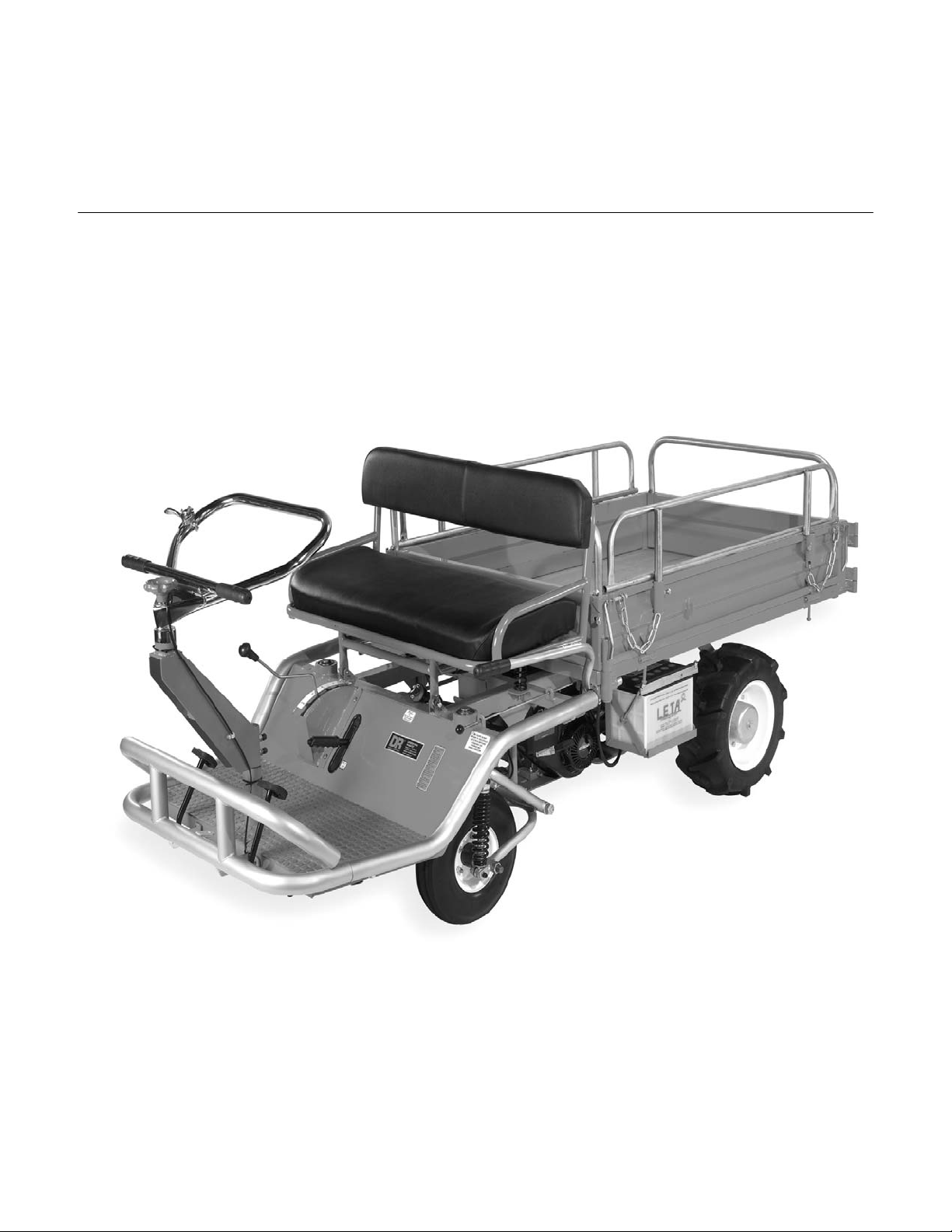
DR® POWERWAGON
4 x 2
Safety and Operating Instructions
Important!
Please read the Safety & Operating Instructions and the separate Engine Manufacturer's Owner's
Manual to become familiar with the basic features of the DR® POWERWAGON™ 4 x 2 before
operating it.
Country Home Products, Inc.
www.dr-owner.com
Page 2

And congratulations on your purchase of a
new DR® POWERWAGON™ 4 X 2!
We have done our utmost to ensure your
DR® POWERWAGON™ 4 X 2 will be one of
the most trouble-free and satisfying pieces of
equipment you have ever owned. Please let us
know of any questions or problems you may
have. We want to answer or correct them as
quickly as possible. (When you do call or
write, please have your serial number and/or
order number handy—it will speed things up!)
We also hope to hear from you on how much
you like your new helper.
And, please tell your friends about your
new DR
DR® Owners spread the word about our
products and our way of doing business is the
best advertising we can have, and the best way
to help us provide even better service in the
years to come.
Thanks once again!
®
POWERWAGON™ 4 X 2. Having
For all of us at...
COUNTRY HOME PRODUCTS
Page 3

Introduction
Your new DR® POWERWAGON™ 4 x 2 is a carefully designed product launched to meet
our customer's needs for a vehicle that can transport one or two people along with a load of
up to 500 pounds on slopes up to 20 degrees and 1000 pounds on level ground. This new
model of Powerwagon™ features easy operation, minimal effort to transport heavy loads,
low fuel consumption, and rugged construction. Since its debut, this bestseller has turned
out to be a favorite worldwide.
All of our products are designed and manufactured to meet our customer’s high standards
for rugged and quality products. This Powerwagon™ 4 x 2 has been extensively tested in
typical home and field environments. As a result, this Powerwagon™ 4 x 2 has shown
outstanding performance, high reliability and easy operation.
Your new DR® POWERWAGON™ 4 x 2 features a low center of gravity, powerful
climbing capability and large payload capacity and can operate under all weather and field
conditions. We are proud to provide you with this safe, comfortable, easy to use and
economical Powerwagon™ 4 x 2.
Please read this manual carefully before operating your DR® Powerwagon™ 4 x 2. It
contains important safety information, and instructions for set up, operation and
maintenance.
COPYRIGHT
2002 Country Home Products, Inc. All rights reserved.
Country Home Products, Inc.
Meigs Road
P.O. Box 25
Vergennes, VT 05491
Toll-free phone: 1-800-DR-OWNER (376-9637)
1-802-877-1213
Fax:
Web site: www.dr-owner.com
E-mail: info@countryhomeproducts.com
Page 3
Page 4

Table Of Contents
Introduction…………………………………………………………………………. 3
Safety Information…………………………………………………………………... 5
Safety With Gas Powered Machines…………………………………………………. 6
Special Note for California and Washington State Owners…………………………... 6
Safety Labels………………………………………………………………………… 6
Transporting the DR® Powerwagon™ 4 x 2………………………………………... 9
Preparing the DR® Powerwagon™ 4 x 2 for Operation…………………………….. 10
Checking and Adding Oil……………………………………………………………. 10
Adding Fuel…………………………………………………………………………. 11
Fuel Shut Off and Cap………………………………………………………………. 11
Connecting the Battery……………………………………………………………… 11
Operator Controls…………………………………………………………………… 12
Engine Choke………………………………………………………………………... 12
Engine Starting………………………………………………………………………. 13
Driving the DR® Powerwagon™ 4 x 2……………………………………………… 14
Installation of the Optional Side Rails……………………………………………….. 15
Cargo Bed Information……………………………………………………………… 15
Rear Cargo Door…………………………………………………………………….. 16
Cargo Bed Lock……………………………………………………………………... 16
Vehicle Weight and Cargo Capacity…………………………………………………. 16
Maintenance Information……………………………………………………………. 17
Tools Required………………………………………………………………………. 17
Engine Oil…………………………………………………………………………… 17
Changing Oil………………………………………………………………………… 17
Spark Plug…………………………………………………………………………… 18
Air Filter……………………………………………………………………………... 18
Transmission………………………………………………………………………… 18
Brake Information…………………………………………………………………… 19
Wheel Shear Bolts…………………………………………………………………… 20
Fuel Filter and System……………………………………………………………….. 20
Belt Information…………………………………………………………………….. 21
Changing Belts……………………………………………………………………… 22
Tire Information……………………………………………………………………. 22
Engine Mounts……………………………………………………………………… 22
Other Lubrication…………………………………………………………………… 22
Checking The Nuts and Bolts……………………………………………………….. 23
Torque Information…………………………………………………………………. 23
Battery Information…………………………………………………………………. 23
Warranty……………………………………………………………………………. 25
Page 4
Page 5

Safety Information
• Dress Appropriately: Wear shoes with non-slip treads or safety shoes if you have them.
Do not operate the machine while barefoot or wearing open sandals. Avoid loose
clothing or jewelry, which might get caught in the machine’s moving parts.
• Check out the area you will be operating in before using your Powerwagon™ 4 x 2.
Avoid excessively rugged or steep terrain.
•
Caution: When traveling in high gear, do not use the pedal brake and the parking brake
at the same time or pull the parking brake and press the clutch at the same time or the
transmission may be damaged.
•
Do not use the parking brake when traveling in high gear.
•
• Drive in low gear when traveling with heavy loads or over rough terrain.
• Slow down when making turns.
• Do not change direction quickly on rough terrain.
• Caution: Do not change gears while in motion. Stop the vehicle to change gears.
• Do not force the shift lever. When the vehicle is stopped pump the brake pedal and
•
• Be sure to keep pedestrians above you at all times when traveling up and down slopes.
• Caution: Only use low gear when traveling up or down slopes.
• Be sure to use the parking brake when stopped.
• Remove the key when not in use to prevent unauthorized use.
• Built in safety features are effective only when maintained and kept in place. Do not,
•
• Keep combustible substances away from engine when hot.
• When using the DR® Powerwagon ™ 4 x 2 don’t take things for granted. When in
• Do Not Overload the DR® Powerwagon™ 4 x2. Be careful of top heavy loads; the
Do not overload. The Powerwagon™ 4 x 2 is rated for 1000 pounds of cargo
weight on hard level ground and 500 on slopes up to 20 degrees.
then the clutch before trying to change gears. You may need to wait a few seconds for
the transmission to stop turning.
Do not carry passengers when traveling up, sideways, or down hills.
under any conditions, remove, cut, bend, weld or change standard parts on any
equipment. A change made on your own can make the vehicle unsafe and may void
your warranty.
Always shut off the engine, allow to cool, remove the spark plug wire, apply
parking brake and chock the wheels prior to making any adjustments to the vehicle.
doubt about the equipment or the surroundings, stop the machine and take the time to
look things over. Make sure that you have 100% control of your machine at all times.
higher the load, the higher the chance the machine may tip over. Also, loads may shift
during operation, so secure your loads and make them even, when possible to be safe.
Page 5
Page 6

• Do not rev the engine. Excessive speed or tampering with the engine governor can be
dangerous.
• Keep your hands away from the belts and pulleys when the engine is running.
• Be particularly careful of small children and pets. Never allow children to operate the
vehicle. Never carry children, adults or pets in the wagon bed. Use caution when
operating the vehicle around other people or animals.
• Do not operate the vehicle under the influence of drugs or alcohol.
Safety with Gasoline- Powered Machines
• Do not run the machine in an enclosed area or without proper ventilation.
• Store all fuel in containers specifically designed for this purpose. Plastic containers are
more likely to prevent sediment and condensation problems.
• Fill the gas tank outdoors with the engine off. Don’t handle gasoline if you or anyone
nearby is smoking, or if you are near a fire, sparks, or anything that could cause gasoline
vapors to ignite or explode.
• If gasoline is spilled, do not attempt to start the engine. Move the machine away from
the area of the spill and avoid creating any source of ignition until the gasoline vapors
have dissipated. Wipe up any spilled fuel to prevent a fire hazard, and properly dispose
of the waste.
• Allow the engine to cool before storing in any enclosure. Never store the machine near
an open flame or sparks.
• Some state and local regulations require the use of a spark arrester on gasoline powered
engines. Contact your local fire marshal or forest service for specific information in your
area. If you are required to use a spark arrester, please contact one of our Customer
Service Representatives 1-800 DR-OWNER (376-9637) who will assist you in obtaining
one.
Special Note for California and Washington State Owners
• California and Washington states require the use of spark arresters on internal
combustion engines. Failure of the owner/ operator to maintain this equipment in
compliance with state regulations is a misdemeanor under California law and may be in
violation of other state and federal regulations. Contact your local fire marshal or forest
service for specific information in your area.
Country Home Products, Inc. reserves the right to discontinue, change and improve its
products at any time without notice or obligation to the purchaser.
The descriptions and specifications contained in this manual were in effect at the time of
printing. Some equipment described in this manual may be optional. Some illustrations may
not be applicable to your machine.
Page 6
Page 7

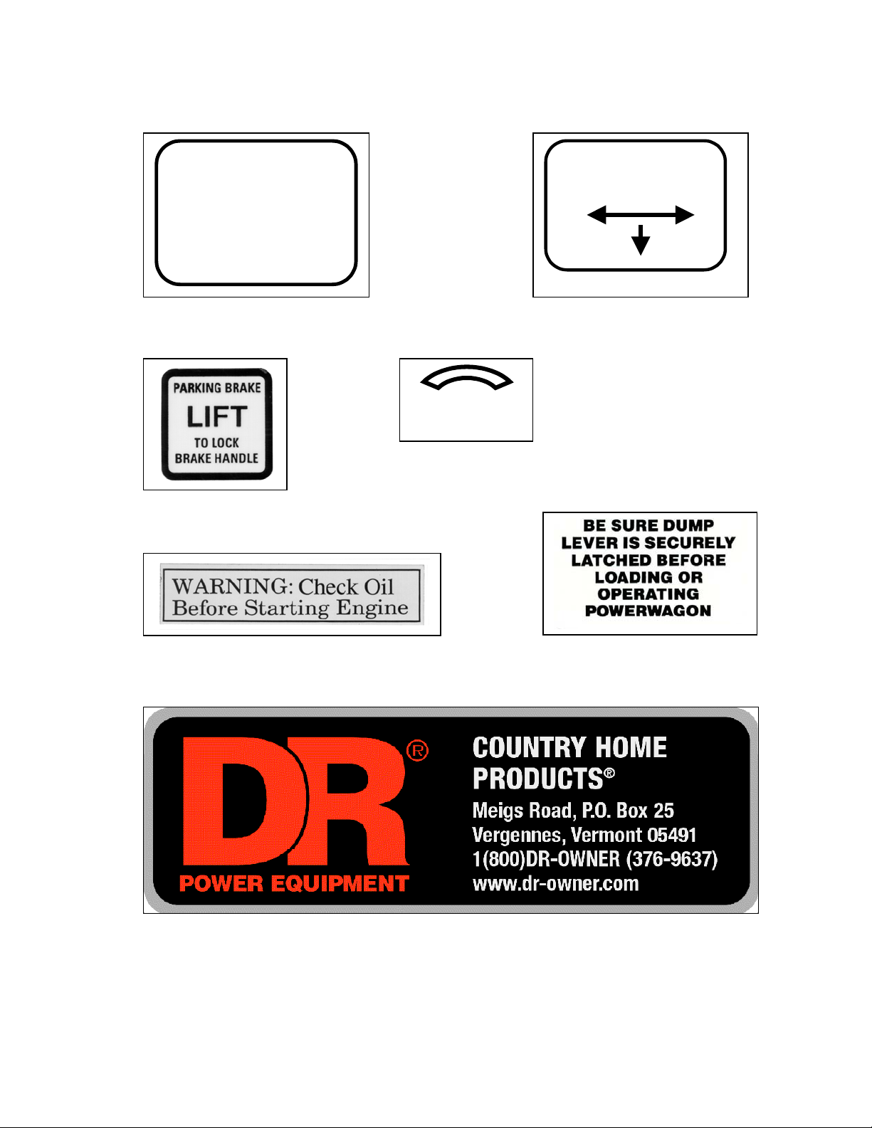
Safety Labels
Take some time to become familiar with these safety information labels. Replace missing or
damaged labels immediately. Note: these illustrations are not actual size.
OPERATE SAFELY
¾ Stop before
Shifting.
¾ Max Load is 500
pounds on a slope
and 1000 pounds on
hard, level ground.
¾ Do not operate on
slopes greater than
20 degrees.
¾ High Speed is 9
MPH. Use care in
HIGH gear.
¾ Use care in turning,
abrupt changes in
direction could cause
the vehicle to turn
over.
¾ Use LOW gear in
rough terrain, on
slopes or in wet
conditions.
¾ Set the Parking
Brake whenever the
vehicle is parked.
BEFORE STARTING
¾ Read Safety Manual
¾ Set the Parking Brake
¾ Check the gas and oil
levels
¾ Check tire pressure
¾ Check that the dump
lever latch is secure.
¾ Use choke on engine for
cold starting
TO START ENGINE
¾ Pu sh in th e clutch
and brake pedals.
¾ Release the parking
brake.
¾ Set the shift lever to
Neutral.
¾ Set the p arking
brake.
¾ Set the throttle at
the halfway position
¾ If en gin e h as not
been used recently,
set the choke lever.
¾ Turn the key to the
starting position and
hold until the engine
starts, but no longer
than 3 seconds.
¾ Release the key
when the engine
starts.
¾ If the choke was
set, then slowly return
the choke lever to the
run position.
¾ Ad just th e throttle.
¾ Release the parking
brake
¾ Set the shift lever to
HIGH, LOW, or
Reverse.
¾ Slowly release the
clutch and brake
pedals.
TO STOP ENGINE
¾ Pu sh in th e clutch
and brake pedals.
¾ Set the P arkin g
Brake.
¾ Turn the key to off.
TO DUMP
¾ Op en the tailgate
and secure it against
the side panel.
¾ Pull the dump lever
release handle.
¾ Lift the dump lever.
¾ Lower the dump
lever and be sure it is
secured.
¾ Close the tailgate.
HIGH
N -
Start
OW
L
N
R
EVERSE
Page 7
Page 8
Model # PWR8-USA
Light Utility Vehicle
Operating Vehicle Weight
650 pounds
Gross Vehicle Weight Limit
2050 pounds on Level
1650 pounds on 20
o
Slope
Choke Lever
Run Choke
SF
Page 8
Page 9

Transporting the DR® POWERWAGON™ 4 x 2
• The DR® Powerwagon™ 4 x 2 can be transported in the bed of a full size pick up truck
or vehicle that can accommodate a pallet 45 x 108 inches, weighing 750 lbs.
• You will need:
• 2 Ramps ( 2 x 10 x 7 ft. long)
• Wire cutters
• Knife
• Hammer
• Screwdriver
• Two helpers
• The DR® Powerwagon™ 4 x 2 is shipped fully assembled, fixed to a pallet. The pallet
can only be loaded on your vehicle one way at the trucking depot. The front of the DR®
Powerwagon™ 4 x 2 will be towards the front of the truck.
• Secure the DR® Powerwagon™ 4 x 2 to your vehicle.
• Upon arrival at home, carefully remove the wrapping from the machine, cut the banding
and remove the wheel chocks.
• Place the ramps from the back of the pallet to the ground. Make sure that the ramps are
lined up with the wheels.
• DO NOT ATTEMPT TO DRIVE THE VEHICLE DOWN THE RAMPS WITH THE
ENGINE RUNNING. DO NOT STAND BEHIND THE VEHICLE WHEN
OFFLOADING.
• You should become familiar with the controls prior to unloading. Please be sure to know
the location of the hand and foot brake as well as the gearshift.
• Be sure to read the Safety and Operating Instructions provided with your machine before
attempting to operate the DR® Powerwagon™ 4 x 2.
Page 9
Page 10

Preparing The DR® POWERWAGON™ 4 x 2 For Operation
A
g
We have done our utmost to make it easy to get your DR© POWERWAGON™ 4 x 2 ready
to roll. Please take a few minutes to read through this manual and your engine manual before
attempting operation.
Checking and Adding Oil:
For your convenience the DR® POWERWAGON™ 4 x 2 is shipped fully assembled, with
oil in the engine and transmission. However it is always wise to check the oil levels before
operation. Make sure that the machine is on a level surface and unscrew the oil cap as shown.
Oil should be at the level shown in figure 1. Add oil with the yellow cap off until oil starts to
drip out. You can add oil here or at the oil fill shown in figure 2.
Oil fill
Oil Level
Figure 1
Checking the Transmission Oil:
The transmission is shipped with gear oil but should
be checked before operation. If necessary, add SAE
90W gear oil until it shows 2/3 in the sight glass. See
Figure 3.
Figure 2
dd Trans. oil
Oil sight window
Drain plu
Figure 3
Page 10
Page 11
Adding Fuel:
)
Caution: Do not smoke or allow others to smoke or have any sparks or other
sources of ignition near by while filling the gas tank. Only fill the tank outdoors.
The fuel tank is located under the seat. See Figure
4. The seat is held on hinges and folds forward
to allow access to the tank. The tank holds
approximately 2 ½ gallons of gasoline. The
DR® POWERWAGON™ 4 x 2 uses regular
unleaded fuel with a minimum octane rating of
85, and should be filled to about 1 ½ inches
below the top of the filler neck to allow for fuel
expansion. Refer to your engine manual for
detailed fuel information.
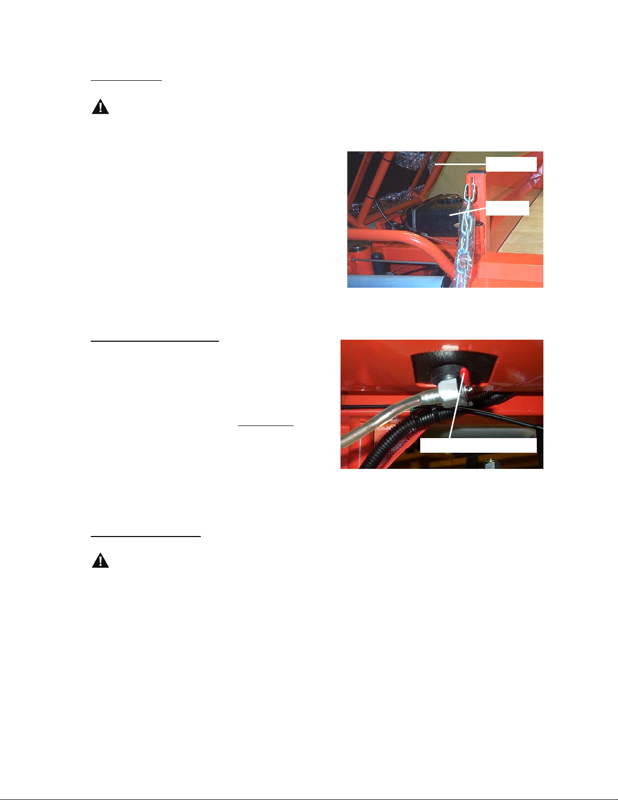
Fuel Shut Off and Cap:
Please take note of the fuel level gage we have
incorporated into the gas cap. Also, there is a
fuel shut off valve at the bottom of the tank.
The lever has a red plastic handle, and off is up
and on is down. See Figure 5. Important:
Please be sure to shut off the fuel lever when
transporting the DR® POWERWAGON™ 4 x
2. Whenever you add fuel inspect the fuel system
for leaks.
Raise Seat
Fuel Tank
Figure 4
Fuel Shut Lever (Off Position
Figure 5
Connect the Battery
Do not smoke or allow others to smoke or have the battery near sparks or other
sources of ignition while performing maintenance on or connecting or disconnecting
the battery.
Your machine is shipped with negative battery cable disconnected. Unscrew the wing nut on
the negative battery post ( - ) and place the green battery wire on the post and replace the wing
nut.
Page 11
Page 12

Operator Controls
Figure 8
Please take some time to become familiar with the operator controls, and their function and
location.
Cargo Bed
Engine Start Switch
Shift
Brake Pedal
Choke
Parking Brake
Cargo Bed Release
Clutch
Figure 6
Your machine is equipped with Operator Presence Safety Devices. The machine will start only with
the handbrake actuated and the gear shift in the neutral start position. Please note that there are two
neutral positions, but only one will allow starting. The starter will crank, but the engine will not start.
After the operator shifts into forward or reverse the operator must be seated for the engine to operate.
Engine choke: The choke control is located next to the engine start switch. (Figure 7) Pulling the
knob forward activates the choke for starting. Pushing the knob fully to the rear de-activates
the choke for normal operation. If necessary, you can access the choke on the engine from the
side by reaching under the frame as shown. (Figure 8.) Move the lever to the right before starting
and then back to the run position once the engine has started.
Choke Location
Choke Cable
Figure 7
Page 12
Page 13

Page 12
p
Engine Starting
Now that you have checked the oil, transmission and fuel and are familiar with the controls
you are ready to start the engine. We know you are anxious to drive your DR®
Powerwagon™ 4 x 2 but here are just a few more tips before you are ready.
• Move choke lever to start.
• Depress the clutch pedal (left pedal) and move the gear selector to the neutral-start
position. Note: if the gear selector seems difficult to shift pump the brake.
• Make sure the parking brake is set.
• Move the throttle (on the left side of the handlebar) to S (slow). Note the throttle location
on the left side of the handlebar in Figure 8-B. We have changed the location after the
cover photo was taken.
Throttle in Slow
osition
Figure 8-B
• Depress the brake pedal (right pedal).
• Turn the key on the start switch and release when the engine starts.
• You can get off the vehicle and move the choke to run.
Page 13
Page 14

Driving the DR® Powerwagon™ 4 x 2
For your first time out it is best to not carry any passengers until you are comfortable with the
vehicle. Take a moment to review your surroundings and terrain. Be aware of all bystanders
and make sure that they are aware of you. Make sure that no bystanders or pets are in front of
or behind the vehicle.
This vehicle is not intended or equipped for public road or highway use. Do not
drive on public roads, highways or sidewalks.
• Start your engine. See Page 13.
• Depress the foot brake.
• Depress the clutch.
• Move the throttle lever to run or fast.
• Release the parking brake.
• Move the gearshift to low gear. If the gear selector does not move easily do not force it.
Slowly pump the foot brake and try again. This is normal; the rear brake and parking
brake are part of the transmission.
Caution: Never try to shift the gears while the vehicle is in motion.
• Slowly take your foot off the brake and slowly release the clutch. As you release the clutch
the vehicle will start to move.
• To stop, depress the clutch and slowly press the foot brake.
• When stopped, place the gear selector in neutral and apply the parking brake.
• Throttle the engine down
• Turn the key to the off position
This same sequence is used for reverse and high gear. Take some time to practice driving in
low and reverse before trying the high gear. The DR® Powerwagon™ will travel
approximately 8 to 9 mph in high gear and this can seem fast, and should only be used on flat
terrain. Note: Top speed is approximate and depends on many factors such as belt wear, tire
pressure, and engine condition. Your top speed may vary.
Caution: Use only low gear when traveling up or down slopes or with loads, or
damage may occur to the belts or transmission.
Page 14
Page 15

Installation of Optional Side Rails
You can purchase the
optional side rails that are
shown in full on the front
cover. Installation is quite
easy. Pry off the caps that
are in the tops of the tubes,
the install the rails as
shown. Screw in the bolts
in all the tubes and tighten
with an adjustable wrench.
Save the caps with your
Operating Manual.
Cargo Bed Information
Figure 10
Latch Bracket
Latch lever
Figure 9
The Cargo bed has simple but sturdy latch
mechanisms as shown in Figure 10. The
sides are hinged at the bottom and the rear
door is hinged at the corner. To unlock,
move the lever to a straight up position
and slide the lever out of the latch bracket
in the direction of the arrow.
One end of the chain can slide off the
lever and hook onto the latch bracket. See
Figure 4 on page 11. This will allow the
side to lay flat if you wish.
Page 15
Page 16

Rear Cargo Door
You can unlatch the bed door the same way as
shown in Figure 10, and swing it all the way
around and latch the door to the side. Secure the
lever to the latch bracket on the bed side. See
Figure 11.
Rear Door
Latch Bracket
Important: Secure the rear bed door raising the
Rear Door
cargo bed.
Figure 11
Cargo Bed Lock
The cargo bed has a lock that can be released by pulling the release lever in the direction of the
arrow as shown in Figure 12.
Cargo Bed Lever
Cargo Bed Release
Important: Always place your hand
on the cargo bed lever when unlocking
the cargo bed to prevent the bed from
tipping with unbalanced loads.
Lift the cargo bed lever to tilt the bed.
There is a rod located above the choke
that can be raised up to keep the bed in
a tilted position.
Try to keep the loads balanced and
even.
Important: Do not overload
Figure 13
Vehicle Weight and Cargo Capacity:
1000 pounds on level ground with two people on board.
500 pounds on a 20-degree slope with one person on board.
The vehicle weighs 650 pounds without cargo or people. The maximum weight limit (vehicle
people and cargo) on level ground is 2050 pounds. On a 20-degree slope the weight limit is
1650 pounds.
Page 16
Page 17
Maintenance Information
The following section contains some useful information on the care and maintenance of your
DR® Powerwagon™ 4 x 2. One of the more important items is checking the engine oil
before you start your engine and changing the oil regularly. Never run your engine with low or
dirty oil.
Tools Required:
You will need metric and fractional wrenches, sockets and Allen wrenches. Also, a set of
straight and Phillips screwdrivers and pliers are needed. The chassis was made exclusively for
us in Taiwan and requires metric tools. The engine, gas tank, and wire harness was
manufactured in the US and requires fractional tools.
Engine Oil:
Your engine holds approximately 7/8 of a quart (28 ounces) of SAE 30 high quality detergent
oil for operation in temperatures 40 degrees F and above. Refer to your engine manual for oil
viscosity in lower operating temperatures.
Caution: The use of multi-viscosity oils (5w-30, 10w-30, etc.) will result in higher than normal
oil consumption. When using multi-viscosity oil, check the oil level often. Multi-viscosity oils
are recommended for use in temperatures below 40 degrees.
Caution: SAE 30 oil, if used below 40 degrees (4 degrees C), will result in hard starting and
possible engine bore damage due to inadequate lubrication.
Check engine oil every 8 hours or daily.
Important: Change the oil after the first 5 hours of use, then every 50 hours or every
season. Change the oil every 25 hours when operating the engine under heavy load or
in high temperatures.
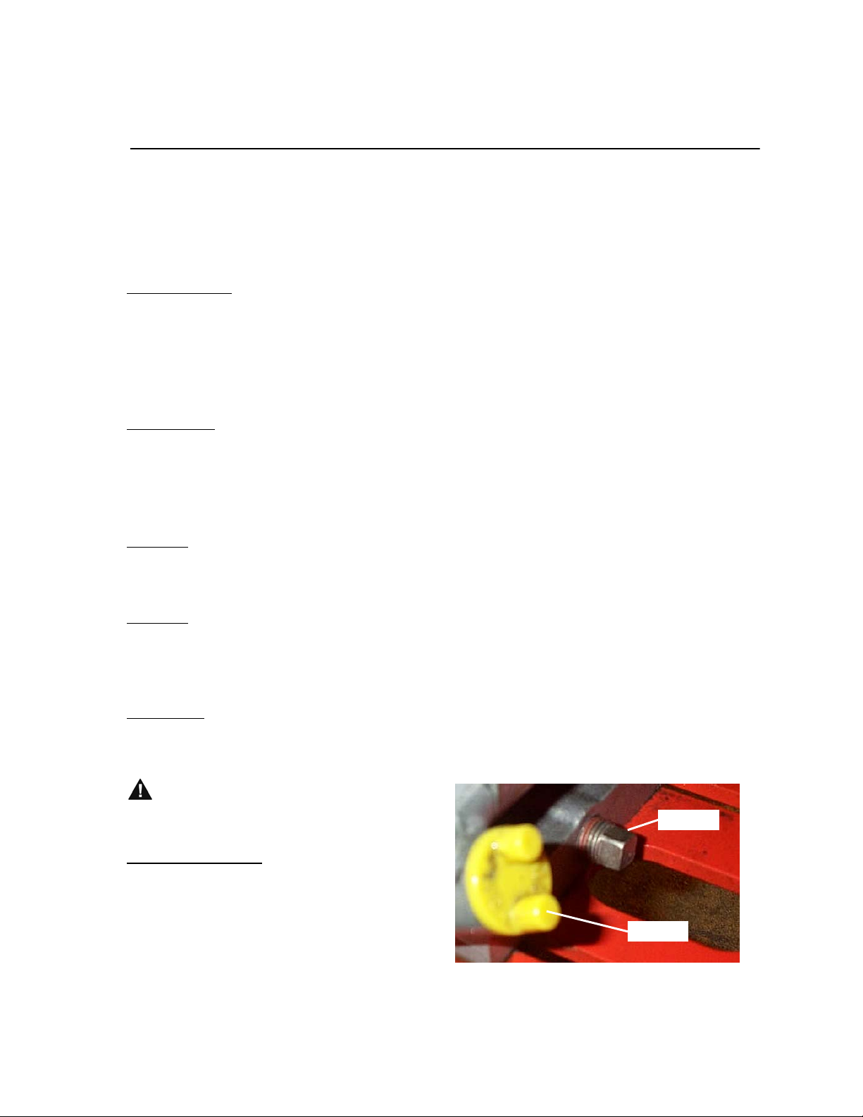
Always disconnect the spark plug
when Servicing the engine or vehicle.
Oil Drain
Changing the Oil:
Allow the engine to cool.
Place a suitable container under the oil drain.
Clean the area around the oil plug and the cap.
Remove the drain plug and allow all the oil to
drain. Replace the plug, remove the oil cap
and add oil until it shows at the level in Figure
1 on Page 10. Replace the cap and recycle the
Figure 14
Oil Cap
Page 17
Page 18

used oil according to your local regulations.
Spark Plug:
The spark plug gap should be set at .030. The plug is a RC12YC resistor type plug. This plug
requires a 5/8 spark plug wrench for removal and installation.
Air Filter:
Always disconnect the spark plug wire before servicing.
Your engine has a flat cartridge type filter element. The Briggs and Stratton number is 491588.
It does not have a pre cleaner. Replacement is recommended every 25 hours or sooner in
dusty environments. Check your filter if your engine runs poorly, idles rough, or lacks power.
Removal requires a 5/16-nut driver or socket
wrench, or a flat head screwdriver. Lift the
cover about an inch so that it clears the tabs on
the bottom of the cover. Then slide the cover
down between the orange chassis and the
spring. The element can then be replaced.
When replacing the cover make sure that the
tabs in the bottom of the cover fit into the slots
on the air cleaner base.
Choke
Air Cleaner
Cover
Screw
See your engine manual for more information.
Figure 15
Transmission:
Always disconnect the spark plug wire before servicing.
The transmission is filled with gear oil at the factory, however it is wise to check it before you
run the DR® Powerwagon™ 4 x 2 and then every eight hours or daily. It requires 2 liters
(2.114 quarts) of 90w-gear oil. It is recommended that you change the oil after 200 hours. See
Figure 3 on Page 10 for the location of the drain, fill and sight glass. When checking the
engine oil make a habit of checking the transmission oil as well. The oil should show 2/3 in
the sight glass.
Page 18
Page 19

Brake Information:
Always disconnect the spark plug wire before servicing.
Adjustment and repair of the brakes should be
Cable Jam Nuts
done carefully to ensure proper braking and that
the front and rear are adjusted together.
The front and rear brakes operate simultaneously
from the foot pedal. The rear brake can be
operated from the hand (parking brake) also. They
are actuated via cables that run from the pedal to
the brake. There are three cables that run to a
Support Bracket
To Brake Pedal
support bracket located under the floor in between
the front wheels. See Figure 16. The bottom cable
Figure 16
is the rear brake. The rear brake also has a support
bracket at the rear end of the cable. See Figure 17.
The cables have adjustment nuts that can lengthen
or shorten the cables.
To Rear Brake
• To shorten the cable and increase the brake
pressure, loosen the nut toward the front of
the machine and tighten the rear nut against
the support bracket.
Rear Support Bracket
• It is recommended that you adjust the front
right and left equally.
• Loosen both forward nuts equally and tighten
Figure 17
the rear nuts so that the brakes are locked on
and then back the rear nuts off ¼ to 3/8 inch. Re-tighten the front nuts.
• Be careful not to over-tighten the cables before you back the nuts off. You just want to
tighten the cable so that the brake levers on the inside of the wheels are fully actuated.
Move those levers by hand so that you get a feel for how much to tighten the cables.
• Adjust the left and right equally or you may find that the vehicle pulls to the right or left.
Caution: After adjusting the brakes, test them. Set the parking brake, start the
engine and press the brake pedal. Depress the clutch and put the vehicle in gear.
Slowly release the clutch. If the vehicle starts to move the brakes must be adjusted
again. If the engine stalls, the brakes are operating properly. Then try operating the
vehicle carefully in low gear at a slow speed without passengers or loads.
Important: The rear wheels have two shear bolts under each wheel hub. These will allow the
rear wheels to continue to rotate for a foot or so before they engage the wheel axle. You will
notice that if you were moving forward when you applied the hand brake the vehicle can still
roll back a foot or so until the shear bolts engage. See the next section for more information.
Page 19
Page 20

Wheel Shear Bolts:
We included two extra shear bolts with your DR® Powerwagon™ 4 x 2. These are meant to
shear before damage can be done to the transmission. If you find that only one wheel is
driving or hear rattling from the rear wheel hubs you may have broken shear bolts. These are
easy to replace. You will need a 14 mm wrench or socket and an 8 mm Allen wrench.
Always disconnect the spark plug wire
before servicing.
Shear Bolts
• Remove the wheel hubcap by removing the
bolt in the center.
• Rotate the wheel slightly to take the tension
off the bolts. The inner hub is slotted. The
Hub Slots
bolts should be away from either end of the
slots.
• If the old bolts are no longer attached, find
the through hole and install the new bolts as
Figure 18
shown in Figure 18.
Fuel Filter and System:
Always disconnect the spark plug wire before servicing.
The fuel line runs from the valve on the fuel tank to a fuel filter. The line runs from the filter
to the engine. There are no user serviceable parts in the filter and it should be replaced every
200 hours, or when it becomes clogged.
Caution: Do not smoke or allow others to smoke or have any sparks or other
sources of ignition near by while filling the gas tank or servicing the fuel system. Only
fill the tank outdoors.
To determine if the filter is clogged, close the valve under the tank. Have a suitable container
handy to catch the fuel. Disconnect the fuel line from either the engine or engine side of the
fuel filter. Put the end of the hose in the container and turn the tank valve on. Fuel should
flow freely through the filter into the container. Remember that the fuel system is gravity fed
and the hose should be lower than the tank.
Your engine does not have a fuel pump and fuel flows only because the tank is higher than the
carburetor.
• Always use fresh, regular gasoline with a minimum 85 octane.
• Only buy gasoline in quantities that you will use up in one month. Gasoline can become
stale and can cause poor engine performance.
• At the end of the season empty the gas tank, and run the engine until it runs out of gas.
This will help keep the carburetor from getting gummed up.
Page 20
Page 21

• Alternately, you can purchase gas stabilizer and add that to the fuel in the tank and then
j
run the engine. Follow the directions on the stabilizer.
Belt Information:
• The DR® Powerwagon™ is equipped with 2 agricultural duty belts. They are 55-inch
belts and the replacement number is 4340-0550L. They should be replaced in pairs.
• If you find that the vehicle is starting to lose speed and power, and the engine is operating
normally you may need to check the belts.
• Always check the engine operation before you adjust the belts. A dirty air filter, clogged
fuel filter, or a fouled spark plug can exhibit the same symptoms.
The belts become tight when you release the clutch pedal. A cable runs from the clutch pedal
to a support bracket. The end of the cable housing is attached to the support bracket with two
nuts. The cable wire then runs to the idler roller lever. The idler roller lever is spring-loaded at
the upper end. The spring runs from the lever to the spring support bracket and is connected
to a threaded adjustment rod. The adjustment rod is attached to the spring support bracket
with two nuts. With the clutch engaged the spring length should be 7 1/4 inches from the end
of the hook to the end of the opposite hook. With the clutch pedal pushed in the spring
should measure 7 7/8 inches. See Figure 21.
Caution: Improper belt tension can cause excessive belt wear and low power if too loose. If
the belts are too tight then it will be hard or impossible to shift gears and transmission damage
could occur.
There are two belt guides that are attached to
Belt Guides
the engine as shown in Figure 19. These are
set at the factory and should never need
adjustment. If you find that removal is
necessary then the upper guide should be set
at 3/8 inches from the belt, and the lower
guide should be 1/4 inch from the belt. These
guides enable the belts to slip on the engine
pulley when the clutch is disengaged. Also
note that the distance between the belts at the
idler pulley should be 2 1/2 inches with the
Clutch Idler Pulley
Clutch Cable
Figure 19
clutch engaged. See Figure 20.
3/8 inch
7 1/4 inches
Clutch Spring
ustment
2 1/2 inches
1/4 inch
Ad
Clutch Cable support bracket
Page 21
Figure 20
Figure 21
Page 22

Caution: If the belt guides are improperly set, it may cause the gears to grind when shifting, or
machine movement even when the clutch is disengaged.
Changing Belts:
Always disconnect the spark plug wire before servicing. Chock the wheels.
• Place the gear shifter in neutral.
• Loosen the nuts at the spring support bracket and disconnect the spring.
• With the belts now loose, it will be possible to roll them off the rear pulley by rotating the
pulley backwards and guiding the belt off. It is easier to roll the inside belt off to the
inside of the rear pulley.
• Take the outside belt off the front pulley.
• If you find that the front belt guides need to be loosened, first clean the area around the
guides with a rag, then scribe or mark their location with a scribe or marker. This will
make replacement easier.
• Take the inside belt off the front pulley.
• Place the new belts on the machine. It is easier to place the belts on the engine pulley first,
then roll them onto the rear pulley.
• Replace the belt guides in the original location, if they were removed.
Tire Information:
In addition to visually checking the tires daily, you should check the tire every 50 hours with a
tire pressure gage. The tires have tubes.
• Front tire pressure should be kept at 30 psi. Type: 4.00-6 4PR The maximum load rating
is 265 pounds at 31 Psi.
• Rear tire pressure should be kept at 26 psi. Type: 19 x 8.00-10 4pr The maximum load
rating is 825 pounds at 34 Psi.
Engine Mounts:
The engine mounting bolts should be checked for tightness every 50 hours. The rubber
engine mounts should be checked every 25 hours for signs of cracking. Check the engine
crankshaft pulley bolt every 50 hours.
Other Lubrication:
Lubricate cables, all pivot points such as the gear shift pivot, dump latch, seat pivot, clutch
idler, and bed pivot every 200 hours or at least once a month with SAE 30W oil.
There are two grease fittings at the rear of the front wheel mounts. These should receive
grease every 50 hours, using good quality lithium grease.
Page 22
Page 23

Checking the Bolts and Nuts:
Be sure to check for loose bolts and nuts and tighten them when necessary.
Be sure to check the wheel hub bolts after using the vehicle for 100 hours or on bi-weekly
basis.
Torque values of the bolts are given as follows: .
Specification Torque
3/8"-16 NC (Ordinary) 30 foot-lbs.
3/8"- 16 NC (Medium) 32 foot-lbs.
7/16-14 NC (Medium) 35 foot-lbs.
M14xP2.0 (Rod Joint) 70 foot-lbs.
Battery Information:
Your DR® Powerwagon™ 4 x 2 has an automotive style 12 volt lead-acid battery.
Maintenance on this battery is similar to that of your car.
Always disconnect the spark plug wire before servicing.
Caution: Always wear eye protection when servicing the battery.
Caution: Always wear acid resistant gloves when servicing the battery
Caution: Never smoke or allow others to smoke or be near any other sources of
ignition when servicing the battery.
• Remove the battery cell cap. Add distilled water to the cell or cells if needed. Replace the
cap.
Important: Remember that battery acid is corrosive and can cause burns. Your battery and
terminals and posts should be cleaned periodically with a mild solution of baking soda and
water, and then rinsed thoroughly with plain water.
Page 23
Page 24

Notes:
Page 24
Page 25

1-Year Limited Warranty
Terms and Conditions
The DR POWERWAGON™ 4 X 2 is warranted for one (1) year against defects in materials or
workmanship when put to ordinary and normal residential use; ninety (90) days for any other use. The
engine is warranted separately by the engine manufacturer.
For the purposes of all the above warranties, “ordinary and normal residential use” refers to noncommercial residential use and does not include misuse, accidents or damage due to inadequate
maintenance.
Country Home Products, Inc. certifies that the DR
purposes for which a product of this type is used. Country Home Products, Inc. however, limits the
implied warranties of merchantability and fitness in duration to a period of one (1) year in residential
use; ninety (90) days for non residential use.
The 1-Year Limited Warranty on the DR
POWERWAGON™ 4 X 2 starts from the date the machine
ships from our factory. The 1-Year Limited Warranty is applicable only to the original owner.
The owner is responsible for the performance of the required maintenance as defined by the
manufacturer's owner's manuals. The owner is responsible for replacement of normally wearing parts
such as belts, bearings, batteries and brake. Attachments and accessories to the machine are not
covered by this warranty.
During the warranty period the warranty holder is responsible for any and all shipping and
transportation charges, if required.
SOME STATES DO NOT ALLOW LIMITATIONS ON THE LENGTH OF IMPLIED
WARRANTIES, SO THE ABOVE LIMITATIONS MAY NOT APPLY TO YOU.
Country Home Products, Inc. shall not be liable under any circumstances for any incidental or
consequential damages or expenses of any kind, including, but not limited to, cost of equipment
rentals, loss of profit, or cost of hiring services to perform tasks normally performed by the DR
POWERWAGON™ 4 X 2.
SOME STATES DO NOT ALLOW THE EXCLUSION OR LIMITATION OF INCIDENTAL
OR CONSEQUENTIAL DAMAGES, SO THE ABOVE LIMITATIONS MAY NOT APPLY TO
YOU.
Customer Service Hotline
Country Home Products, Inc.’s objective is to have 100% satisfied customers. For that reason, we
operate a 6-day-a-week Technical Service Department for our Owners. You can access a
Representative by dialing our TOLL-FREE Hotline at 1-800-DR-OWNER(376-9637). The sole job of
our well-trained and friendly folks is to ensure that you get any help you need in a timely fashion. They
are there to answer all your questions including (1) inquiries on any of the above warranties, (2)
inquiries about replacement parts, or (3) your questions regarding service, maintenance and operation.
Our Customer Service Representatives will also be happy to answer any of your questions regarding the
separate warranties on all engines. However, to obtain service, repair or replacement of any engine
within the time period covered by the manufacturer’s limited warranty, follow the instructions and
warranty information specifically pertaining to those items provided by their separate manufacturers.
THIS WARRANTY GIVES YOU SPECIFIC LEGAL RIGHTS, AND YOU ALSO HAVE OTHER
RIGHTS THAT VARY FROM STATE TO STATE.
POWERWAGON™ 4 X 2 is fit for ordinary
COUNTRY HOME PRODUCTS, Inc.
Meigs Road, P.O. Box 25, Vergennes, Vermont 05491
1-800-DR-OWNER(376-9637) • www.dr-owner.com
Page 25
©2002 CHP, Inc.
Page 26

Daily Checklist for the DR® Powerwagon™ 4 x 2
To help maintain your DR® for optimum performance, we recommend you follow this
checklist each tome you use your machine.
9 GAS: Fill the gas tank with clean, fresh, unleaded gas.
9 OIL: Check the oil and add more if necessary (do not overfill).
9 SPARK PLUG: Clean the spark plug and replace if needed.
9 AIR FILTER: A clean air filter will mean an easier starting and better running engine. You
should replace the paper air filter every 25 hours of use or more frequently if you are using
the machine in dusty conditions.
9 ENGINE AIR-COOLING SYSTEM: It is important to keep the engine clean of debris.
Regularly remove debris from the blower housing and cooling fins. A dirty engine retains
heat and can cause damage to the internal engine parts.
9 BELTS: Check the belts for wear, proper alignment and tension.
9 TRANSMISSION: Check the gear oil level at the sight window and make sure it shows in
2/3 of the window. Add SAE 90 gear oil if necessary.
COUNTRY HOME PRODUCTS, Inc.
Meigs Road, P.O. Box 25, Vergennes, Vermont 05491
1-800-DR-OWNER(376-9637) • www.dr-owner.com
Page 26
©2002 CHP, Inc. 164241
 Loading...