

Page 1

DR
®
SNOW THROWER ATTACHMENT
SAFETY & OPERATING INSTRUCTIONS
30" Single Stage SNOW THROWER for use with DR® FIELD and BRUSH MOWERS
PLEASE READ AND UNDERSTAND THIS MANUAL AND ALL
INSTRUCTIONS BEFORE OPERATING THIS ATTACHMENT.
Page 2

Congratulations on your purchase of a new DR SNOW THROWER ATTACHMENT!
We have done our utmost to ensure that your DR SNOW THROWER ATTACHMENT will be one of the most
trouble-free and satisfying pieces of equipment you have ever owned. Please let us know of any questions
you may have. We want to answer or correct them as quickly as possible. When you do call, please have
your serial number and/or order number handy. For technical assistance, please call Toll-Free 1-800-DR-
OWNER (376-9637) and one of our Technical Support Representatives will be happy to help you. We also
hope to hear from you on how much you like your new helper.
In addition, please tell your friends about your new DR SNOW THROWER ATTACHMENT! Having owners
spread the word about our products and our way of doing business is the best advertising we can have, and
the best way to help us provide even better service in the years to come.
Thanks once again!
for all of us at
OUNTRY HOME PRODUCTS, INC.
C
®
SALES MANAGER
COPYRIGHT
©2007 Country Home Products, Inc. All rights reserved.
®
DR
Power Equipment
A division of Country Home Products®
127 Meigs Road
Vergennes, VT 05491
Toll-Free phone: 1-800-DR-OWNER (376-9637)
Fax: 1-802-877-1213
Web site:
www.dr-owner.com
ii DR® SNOW THROWER ATTACHMENT
Page 3

Table of Contents
CHAPTER 1 ................................................................................................................................................ 1
INTRODUCING THE DR SNOW THROWER ATTACHMENT ........................................................... 1
Conventions used in this manual ........................................................................................................ 1
Specifications ........................................................................................................................................ 2
CHAPTER 2 ................................................................................................................................................ 3
GENERAL SAFETY RULES.................................................................................................................... 3
Labels .................................................................................................................................................... 3
Protecting Yourself and Those Around You ........................................................................................5
Safety for Children and Pets ................................................................................................................. 6
Safety with Gasoline-Powered Engines ................................................................................................ 6
General Safety ....................................................................................................................................... 7
Additional Information and Potential Changes ................................................................................... 8
CHAPTER 3 ................................................................................................................................................ 9
SETTING UP YOUR DR SNOW THROWER ATTACHMENT ............................................................. 9
Unpacking ............................................................................................................................................. 9
Attaching the Discharge Chute........................................................................................................... 11
Removing the Mower Brush Deck...................................................................................................... 12
Installing the DR SNOW THROWER ATTACHMENT....................................................................... 13
Installing the Rotation Handle ........................................................................................................... 14
Attaching the Optional Drift Cutters.................................................................................................. 15
Removing the DR SNOW THROWER ATTACHMENT ..................................................................... 16
CHAPTER 4 .............................................................................................................................................. 17
OPERATING YOUR DR SNOW THROWER ATTACHMENT............................................................ 17
Chute Rotation .................................................................................................................................... 19
Adjusting the Deflector....................................................................................................................... 19
Adjusting the Skid Shoes.................................................................................................................... 20
Operating the DR SNOW THROWER ATTACHMENT ..................................................................... 21
Snow Removal..................................................................................................................................... 22
Snow Removal Methods..................................................................................................................... 23
Cold Weather Operation..................................................................................................................... 23
CHAPTER 5 .............................................................................................................................................. 25
MAINTAINING THE DR SNOW THROWER ATTACHMENT .......................................................... 25
Regular Maintenance Check List before each use ............................................................................. 25
Torque Specification Table ................................................................................................................. 26
Removing and Replacing the Drive Chain ......................................................................................... 27
Removing and Replacing the Drive Belt............................................................................................. 28
Replacing the Shear-Bolt .................................................................................................................... 29
Lubrication ......................................................................................................................................... 30
End of Season and Storage................................................................................................................. 30
CHAPTER 6 .............................................................................................................................................. 31
TROUBLESHOOTING........................................................................................................................ 31
Troubleshooting Table........................................................................................................................ 31
CHAPTER 7 .............................................................................................................................................. 32
PARTS LISTS, SCHEMATIC DIAGRAMS AND WARRANTY............................................................. 32
Parts List - Main Body, 30" DR SNOW THROWER ATTACHMENT ................................................ 32
Schematic - Main Body, 30" DR SNOW THROWER ATTACHMENT............................................... 33
CALL TOLL FREE 1-800-DR-OWNER iii
Page 4

Parts List and Schematic - Chute with Deflector ............................................................................... 34
Parts List and Schematic - Manual Chute Rotation System.............................................................. 35
Parts List and Schematic - Optional Drift Cutter............................................................................... 36
Notes .................................................................................................................................................. 37
Warranty ............................................................................................................................................. 39
Daily Checklist for the DR SNOW THROWER ATTACHMENT ........................................................ 40
iv DR® SNOW THROWER ATTACHMENT
Page 5

CHAPTER 1
INTRODUCING THE DR SNOW THROWER ATTACHMENT
This manual will help you set up and safely operate your new DR SNOW THROWER ATTACHMENT. Careful
adherence to the safety and operating instructions in this manual will ensure many years of productive use.
Please let us know of any questions you may have. We want to answer them as quickly as possible. When
you do call, please have your serial number and/or order number handy. For technical assistance, please call
Toll-Free 1-800-DR-OWNER (376-9637) and one of our Technical Support Representatives will be happy to
help you.
Conventions used in this manual
THIS INDICATES A HAZARDOUS SITUATION, WHICH, IF NOT AVOIDED, COULD RESULT IN DEATH OR
SERIOUS INJURY.
THIS INDICATES A HAZARDOUS SITUATION, WHICH, IF NOT AVOIDED, COULD RESULT IN MINOR OR
MODERATE INJURY
.
THIS INFORMATION IS IMPORTANT IN THE PROPER USE OF YOUR MACHINE. FAILURE TO FOLLOW THIS
INSTRUCTION COULD RESULT IN DAMAGE TO YOUR MACHINE OR PROPERTY.
Tip:
This is a helpful hint to guide you in getting the most out of your DR SNOW THROWER ATTACHMENT.
Tools Needed: This indicates you will need a special tool to perform a maintenance function on your
machine.
NOTE: This information may be helpful to you.
If you are ever unsure about an action you are about to take, don’t do it. Contact Country Home Products’
Toll-Free support at 1-800-DR-OWNER (376-9637) for help or information.
CALL TOLL FREE 1-800-DR-OWNER 1
Page 6

Specifications
Country Home Products, Inc. Single Stage DR SNOW THROWER ATTACHMENT
Overall width 30-1/2"
Overall height (without chute) 18-3/4"
Overall height (with chute) 35-1/2"
Overall length 29-1/2 "
Inlet width 29-3/4"
Inlet height 17-7/8"
Frame thickness 12 gauge
Side thickness 12 gauge
Number of stages 1
Drive "V" type Belt and "V" type Pulley
Drive Pulley 6" O.D.
Idler belt adjustment Automatic Spring Tensioner
Auger Drive #40 Chain and Sprockets
Ratio 2.82:1
Auger RPM 1100 RPM
Idler chain adjustment Automatic Spring Tensioner
Auger diameter 11-3/4"
Auger pitch 11-3/4"; Dual Pitch
Chute position Center
Chute rotation Manual
Adjustable Deflector Yes
Adjustable Skid Shoes Yes
Replaceable Cutting Edge Yes
Shear-Bolt on Drive Pulley Yes
Drift Cutters Optional
Hitch System Fixed to DR Field and Brush Mower
Weight with Chute 138 lbs.
2 DR® SNOW THROWER ATTACHMENT
Page 7
CHAPTER 2
GENERAL SAFETY RULES
• READ THIS SAFETY
ATTACHMENT. BECOME FAMILIAR WITH THE OPERATION AND SERVICE RECOMMENDATIONS TO
ENSURE THE BEST PERFORMANCE FROM YOUR NEW SNOW THROWER. ALSO, REVIEW THE SAFETY
OPERATING INSTRUCTIONS FOR YOUR DR FIELD and BRUSH MOWER BEFORE THE SET UP AND
OPERATION OF THE DR SNOW THROWER ATTACHMENT.
&
OPERATING INSTRUCTIONS MANUAL BEFORE YOU USE THE DR SNOW THROWER
&
• THOROUGHLY INSPECT THE AREA IN WHICH YOU WILL BE WORKING AND REMOVE ALL OBJECTS THAT
COULD DAMAGE THE SNOW THROWER.
• THIS IS A HIGH-POWERED MACHINE, WITH MOVING PARTS OPERATING WITH HIGH ENERGY AT HIGH
SPEEDS. YOU MUST USE PROPER CLOTHING AND SAFETY GEAR WHEN OPERATING THIS MACHINE TO
PREVENT OR MINIMIZE THE RISK OF SEVERE INJURY. THIS MACHINE CAN CRUSH, GRIND, CUT, AND
SEVER PARTS OF YOUR BODY IF THEY ENTER THE INLET OR DISCHARGE AREA OF YOUR DR SNOW
THROWER ATTACHMENT.
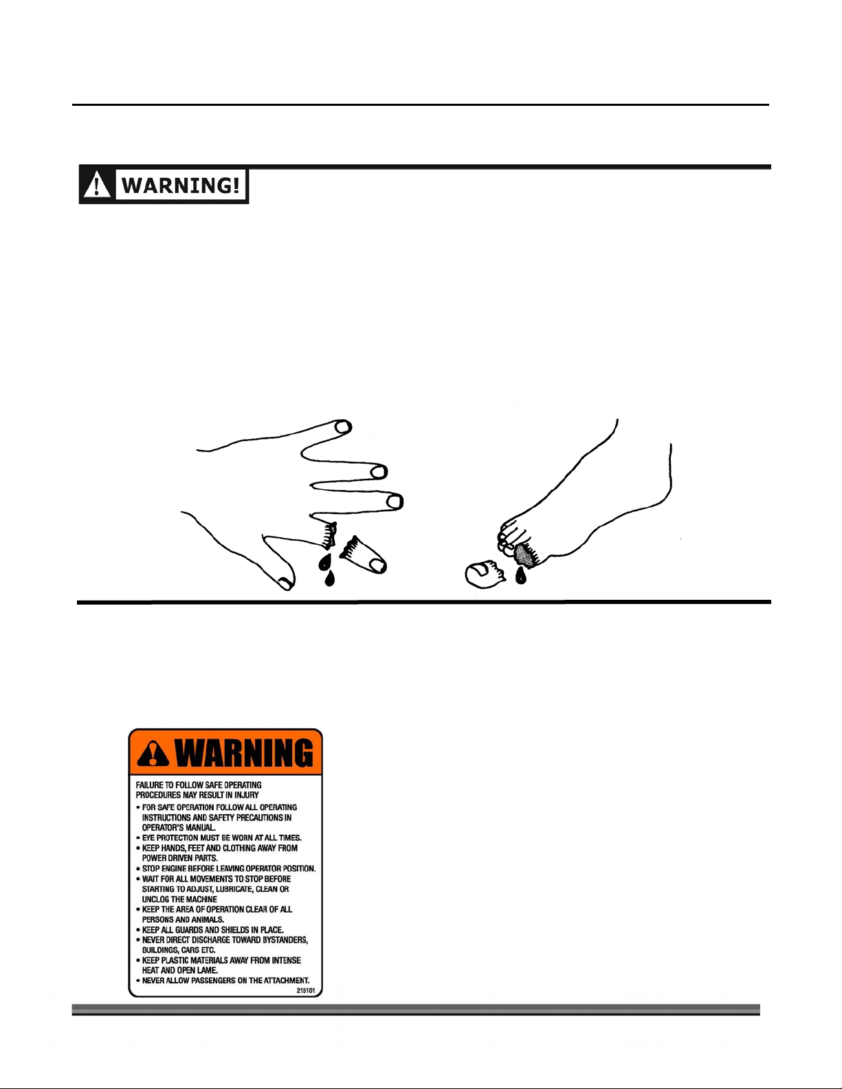
Labels
Your DR SNOW THROWER ATTACHMENT carries prominent labels as reminders for its proper and safe
use. Shown below are copies of all the labels that appear on the equipment. Take a moment to study them
and make a note of their location on your DR SNOW THROWER ATTACHMENT as you assemble and before
you operate the unit. Replace damaged or missing safety and information labels immediately.
CALL TOLL FREE 1-800-DR-OWNER 3
Make sure to read and observe all Warnings before operating
the machine. (#215101)
Page 8
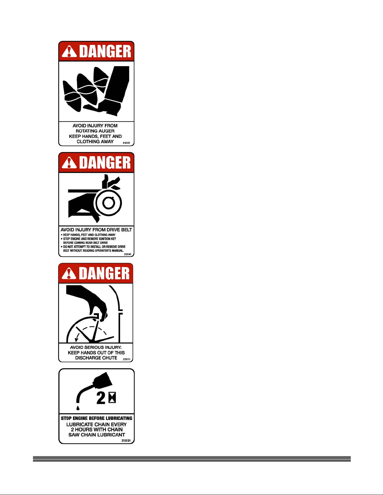
Keep your hands, feet, and clothing away from the rotating Auger.
(#215121)
Keep your hands, feet, and clothing away from the Drive Belt, and
shut off the Power Unit engine before servicing. (#215141)
Keep your hands out of the Discharge Chute. (#215111)
4 DR® SNOW THROWER ATTACHMENT
Stop the engine and lubricate the Drive Chain after every two (2)
hours of operation. (#215131)
Page 9

Protecting Yourself and Those Around You
THIS IS A HIGH-POWERED MACHINE, WITH MOVING PARTS OPERATING WITH HIGH ENERGY AT HIGH
SPEEDS. YOU MUST OPERATE THE MACHINE SAFELY. UNSAFE OPERATION CAN CREATE A NUMBER OF
HAZARDS FOR YOU, AS WELL AS ANYONE ELSE IN THE NEARBY AREA. ALWAYS TAKE THE FOLLOWING
PRECAUTIONS WHEN OPERATING THIS MACHINE:
• ALWAYS SET THE PARKING BRAKE AND BE SURE THE SNOW THROWER AUGER (BLADE) AND WHEEL
CONTROLS ARE DISENGAGED BEFORE ATTEMPTING TO START THE ENGINE ON YOUR DR FIELD
AND BRUSH MOWER.
• ALWAYS WEAR PROTECTIVE GOGGLES OR SAFETY GLASSES WITH SIDE SHIELDS WHILE OPERATING
THE SNOW THROWER TO PROTECT YOUR EYES FROM POSSIBLE THROWN DEBRIS.
• AVOID WEARING LOOSE CLOTHING OR JEWELRY, WHICH CAN CATCH ON MOVING PARTS OR
CONTROLS.
• WE RECOMMEND THAT YOU WEAR ADEQUATE WINTER GARMENTS WHEN OPERATING THE SNOW
THROWER. BE SURE YOUR GLOVES FIT PROPERLY AND DO NOT HAVE LOOSE CUFFS OR
DRAWSTRINGS.
• USE EAR PROTECTORS OR EAR PLUGS RATED FOR AT LEAST 20 DBA TO PROTECT YOUR HEARING.
• NEVER ALLOW PEOPLE WHO ARE UNFAMILIAR WITH THESE INSTRUCTIONS TO USE THE DR SNOW
THROWER ATTACHMENT. ALLOW ONLY RESPONSIBLE INDIVIDUALS WHO ARE FAMILIAR WITH
THESE RULES OF SAFE OPERATION TO USE YOUR MACHINE.
• KEEP YOUR HANDS AND FEET AWAY FROM THE BELTS, CHAINS, PULLEYS, AND CONCEALED AREAS
WHILE THE ENGINE IS RUNNING. NEVER REACH IN THE SNOW THROWER CHUTE OR AUGER AREA
WHEN THE ENGINE IS RUNNING.
• WATCH FOR TRAFFIC WHEN OPERATING IN OR NEAR ROADWAYS. PAY EXTRA ATTENTION WHEN
OPERATING NEAR PUBLIC ROADWAYS.
• BE AWARE OF YOUR SURROUNDINGS WHEN OPERATING THE DR SNOW THROWER ATTACHMENT,
E.G., DITCHES, CULVERTS, DROP-OFFS, AND HILLS.
• KEEP BYSTANDERS AWAY FROM YOUR WORK AREA AT ALL TIMES. SNOW AND ICE EXIT THE
MACHINE AT HIGH SPEED. TO BE SAFE, DO NOT OPERATE THE MACHINE NEAR SMALL CHILDREN
OR PETS, AND NEVER ALLOW CHILDREN TO OPERATE THE MACHINE. DISENGAGE THE SNOW
THROWER AND STOP THE ENGINE WHEN ANOTHER PERSON OR PET APPROACHES.
• ALWAYS OPERATE THE SNOW THROWER FROM THE “OPERATOR ZONE” (FIGURE 10 ON PAGE 14).
NEVER PASS BY THE DISCHARGE CHUTE WHEN THE ENGINE IS RUNNING OR THE AUGER IS
TURNING.
• ALWAYS DISENGAGE THE SNOW THROWER BELT DRIVE, TURN OFF THE POWER UNIT ENGINE AND
REMOVE THE SPARK PLUG WIRE(S) BEFORE CLEANING, ADJUSTING OR SERVICING THE SNOW
THROWER.
• USE EXTRA CARE WHEN APPROACHING BLIND CORNERS, SHRUBS, TREES, OR OTHER
OBSTRUCTIONS THAT MIGHT HIDE PEOPLE OR PETS FROM SIGHT.
• CLEAR THE AREA OF OBJECTS SUCH AS SLEDS AND SHOVELS, ETC. INGESTING THESE OBJECTS INTO
THE SNOW THROWER COULD DAMAGE THE MACHINE AND/OR CAUSE INJURY.
• NEVER, UNDER ANY CONDITIONS, REMOVE, BEND, CUT, FIT, WELD, OR OTHERWISE ALTER
STANDARD PARTS ON THE DR SNOW THROWER ATTACHMENT. MODIFICATIONS TO YOUR
MACHINE COULD CAUSE PERSONAL INJURIES AND PROPERTY DAMAGE AND WILL VOID YOUR
WARRANTY.
CALL TOLL FREE 1-800-DR-OWNER 5
Page 10

Safety for Children and Pets
TRAGIC ACCIDENTS CAN OCCUR IF THE OPERATOR IS NOT ALERT TO THE PRESENCE OF CHILDREN AND
PETS. CHILDREN ARE OFTEN ATTRACTED TO THE MACHINE AND THE SNOW THROWING ACTIVITY.
NEVER
PRECAUTIONS:
ASSUME THAT CHILDREN WILL REMAIN WHERE YOU LAST SAW THEM. ALWAYS FOLLOW THESE
• KEEP CHILDREN AND PETS OUT OF THE WORKING AREA AND UNDER THE WATCHFUL CARE OF A
RESPONSIBLE ADULT.
• BE ALERT AND TURN THE MACHINE OFF IF CHILDREN OR PETS ENTER THE WORK AREA.
• NEVER ALLOW CHILDREN TO OPERATE THE MACHINE.
Safety with Gasoline-Powered Engines
GASOLINE IS A HIGHLY FLAMMABLE LIQUID. GASOLINE ALSO GIVES OFF FLAMMABLE VAPOR THAT
CAN BE EASILY IGNITED AND CAUSE A FIRE OR EXPLOSION. NEVER OVERLOOK THE HAZARDS OF
GASOLINE. ALWAYS FOLLOW THESE PRECAUTIONS:
• DO NOT RUN THE ENGINE INDOORS EXCEPT TO TRANSPORT THE DR SNOW THROWER
ATTACHMENT IN OR OUT OF A BUILDING AS YOU COULD BREATHE IN DANGEROUS CARBON
MONOXIDE GAS FROM THE ENGINE EXHAUST.
• STORE ALL FUEL AND OIL IN CONTAINERS SPECIFICALLY DESIGNED AND APPROVED FOR THIS
PURPOSE AND KEEP AWAY FROM HEAT AND OPEN FLAME, AND OUT OF THE REACH OF CHILDREN.
• FILL THE GASOLINE TANK OUTDOORS WITH THE ENGINE OFF AND ALLOW THE ENGINE TO COOL
COMPLETELY. DO NOT HANDLE GASOLINE IF YOU OR ANYONE NEARBY IS SMOKING, OR IF YOU
ARE NEAR ANYTHING THAT COULD CAUSE IT TO IGNITE OR EXPLODE. REPLACE THE FUEL TANK
AND FUEL CONTAINER CAPS SECURELY.
• IF YOU SPILL GASOLINE, DO NOT ATTEMPT TO START THE ENGINE. MOVE THE MACHINE AWAY
FROM THE AREA OF THE SPILL AND
VAPORS HAVE DISSIPATED. WIPE UP ANY SPILLED FUEL TO PREVENT A FIRE HAZARD AND PROPERLY
DISPOSE OF THE WASTE.
AVOID CREATING ANY SOURCE OF IGNITION UNTIL THE GAS
• ALLOW THE ENGINE TO COOL COMPLETELY BEFORE STORING IN ANY ENCLOSURE. NEVER STORE
THE MACHINE WITH GAS IN THE TANK OR A FUEL CONTAINER, NEAR AN OPEN FLAME OR SPARK
SUCH AS A WATER HEATER, SPACE HEATER, CLOTHES DRYER OR FURNACE.
• NEVER MAKE ADJUSTMENTS OR REPAIRS WITH THE POWER UNIT ENGINE RUNNING.
• DO NOT CHANGE THE ENGINE GOVERNOR SETTINGS OR MODIFY THE ENGINE SPEED.
• NEVER TAMPER WITH SAFETY DEVICES. CHECK THEIR PROPER OPERATION REGULARLY.
6 DR® SNOW THROWER ATTACHMENT
Page 11

General Safety
YOU MUST OPERATE THE DR SNOW THROWER ATTACHMENT SAFELY TO PREVENT OR MINIMIZE THE
RISK OF DEATH OR SERIOUS INJURY
YOU. ALWAYS TAKE THE FOLLOWING PRECAUTIONS WHEN OPERATING THIS MACHINE:
• KEEP IN MIND THAT THE OPERATOR OR USER IS RESPONSIBLE FOR ACCIDENTS OR HAZARDS
OCCURRING TO OTHER PEOPLE, THEIR PROPERTY, AND THEMSELVES.
• YOUR DR SNOW THROWER ATTACHMENT IS A POWERFUL TOOL, NOT A PLAYTHING. EXERCISE
EXTREME CAUTION AT ALL TIMES. THE DESIGN OF YOUR MACHINE IS TO THROW SNOW. DO NOT
USE IT FOR ANY OTHER PURPOSE.
• KNOW HOW TO STOP THE MACHINE QUICKLY IN CASE OF EMERGENCY BY DISENGAGING THE
SNOW THROWER (BLADE CONTROL) AND SHUTTING DOWN THE POWER UNIT ENGINE.
• ALWAYS DISENGAGE SNOW THROWER (BLADE CONTROL), MAKE CERTAIN THE AUGER AND ALL
MOVING PARTS HAVE COME TO A COMPLETE STOP, SHUT OFF THE POWER UNIT ENGINE AND
REMOVE THE KEY WHENEVER YOU LEAVE THE OPERATING POSITION OR IF YOU HAVE TO STOP TO
REMOVE SNOW FROM THE MACHINE.
• KEEP COMBUSTIBLE SUBSTANCES AWAY FROM THE POWER UNIT ENGINE WHEN IT IS HOT.
• STAY ALERT FOR HIDDEN HAZARDS OR TRAFFIC WHEN OPERATING NEAR A ROADWAY.
• DO NOT CARRY PASSENGERS ON YOUR DR SNOW THROWER ATTACHMENT.
• EXERCISE EXTREME CAUTION WHEN OPERATING ON OR CROSSING GRAVEL DRIVEWAYS, WALKS, OR
ROADS. MAKE SURE TO ADJUST THE HEIGHT OF THE SKID SHOES SO THE CUTTING EDGE WILL
CLEAR GRAVEL OR CRUSHED ROCK SURFACES.
• DO NOT ATTEMPT TO OPERATE THE MACHINE ON STEEP SLOPES OR NEAR EMBANKMENTS.
• USE CAUTION WHEN BACKING UP THE SNOW THROWER.
• SEE MANUFACTURER’S INSTRUCTIONS FOR PROPER OPERATION AND INSTALLATION OF
ACCESSORIES. ONLY USE ACCESSORIES APPROVED BY COUNTRY HOME PRODUCTS, INC.
• IF THE SNOW THROWER AUGER STRIKES A FOREIGN OBJECT OR IF YOUR MACHINE SHOULD START
MAKING AN UNUSUAL NOISE OR VIBRATION, IMMEDIATELY DISENGAGE AUGER (BLADE CONTROL),
STOP THE POWER UNIT ENGINE, WAIT FOR ALL MOVING PARTS TO COME TO A COMPLETE STOP AND
DISCONNECT THE SPARK PLUG WIRE(S). VIBRATION IS GENERALLY A WARNING OF TROUBLE. INSPECT
FOR CLOGGING OR DAMAGE. CLEAN AND REPAIR AND/OR REPLACE DAMAGED PARTS.
• WHILE USING THE DR SNOW THROWER ATTACHMENT, DO NOT HURRY OR TAKE THINGS FOR
GRANTED. WHEN IN DOUBT ABOUT THE EQUIPMENT OR YOUR SURROUNDINGS, STOP THE
MACHINE AND TAKE THE TIME TO LOOK THINGS OVER.
• NEVER OPERATE THE MACHINE WHEN UNDER THE INFLUENCE OF ALCOHOL, DRUGS, OR
MEDICATION.
• USE THE MACHINE ONLY IN DAYLIGHT OR GOOD ARTIFICIAL LIGHT.
• KEEP ALL SHIELDS IN PLACE AND MAKE CERTAIN NUTS AND BOLTS ARE TIGHT TO ASSURE A SAFE
WORKING CONDITION AND ALWAYS USE THE SUPPLIED SELF-LOCKING HARDWARE; DO NOT
SUBSTITUTE.
• WEAR BOOTS WITH NON-SLIP TREADS WHEN USING YOUR DR SNOW THROWER ATTACHMENT.
• NO LIST OF WARNINGS AND CAUTIONS CAN BE ALL-INCLUSIVE. IF SITUATIONS OCCUR THAT ARE
NOT COVERED BY THIS MANUAL, THE OPERATOR MUST APPLY COMMON SENSE AND OPERATE THIS
MACHINE IN A SAFE MANNER. CALL 1-800-DR-OWNER (376-9637) FOR ASSISTANCE.
. UNSAFE OPERATION CAN CREATE A NUMBER OF HAZARDS FOR
CALL TOLL FREE 1-800-DR-OWNER 7
Page 12

Additional Information and Potential Changes
Country Home Products, Inc. reserves the right to discontinue, change, and improve its products at any
time without notice or obligation to the purchaser. The descriptions and specifications contained in this
manual were in effect at printing. Equipment described within this manual may be optional. Some
illustrations may not be applicable to your machine.
8 DR® SNOW THROWER ATTACHMENT
Page 13

CHAPTER 3
SETTING UP YOUR DR SNOW THROWER ATTACHMENT
This chapter outlines unpacking and a few simple steps you will need to follow to set up your new Snow
Thrower and attach it to your DR FIELD and BRUSH MOWER. If you have any questions at all, please feel
free to contact our Customer Service Representatives at our Toll-Free number: 1-800-DR-OWNER (376-9637).
Unpacking
NOTE: We recommend two people for the unpacking procedure, as the unit weighs 138 pounds.
Tools and Supplies Needed:
• Knife
• Gloves
• Metal Shears (Side Cutters)
• 7/16" Wrench or Socket
• Eye Protection
Parts Supplied:
• DR SNOW THROWER ATTACHMENT
• Rotation Handle
• Worm Shaft
• V-Belt
• Parts Box containing:
- Handle Support
- Chute Assembly
- (3) Retaining Plates
- U-Bolt, 1/4" NC x 1-1/8" x 2"
- (2) Plastic Bushings
- (6) Hex Head Bolts, 1/4" NC x 1/2"
- (6) Flange Nuts, 1/4" NC
- Flat Washer, Worm Shaft
- Hair Pin, 2 mm x 41 mm
- Cotter Pin, 1/8" x 1-3/4"
&
- Safety
- Packing List
- (3) Spare Shear-Bolt & Nut
- Washer, Chute Base
Operating Instructions
CALL TOLL FREE 1-800-DR-OWNER 9
Page 14
•
WEAR EYE PROTECTION WHEN CUTTING THE BANDING. THE BANDING IS UNDER HIGH TENSION
AND MAY SNAP AND STRIKE YOU WHEN CUT. STAND TO ONE SIDE WHEN CUTTING THE
BANDING.
• STABILIZE THE SHIPPING CONTAINER ON CLEAN FLAT TERRAIN BEFORE ATTEMPTING TO UNPACK
AND ASSEMBLE THE MACHINE.
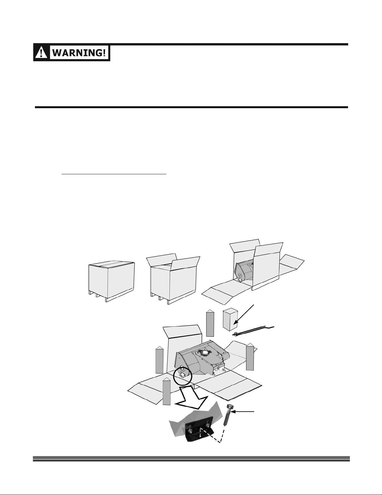
1. Stand to one side and cut the banding around the carton.
2. Open the top of the stapled cardboard carton (Figure 1) and fold the sides down. The staples are
sharp so be careful.
3. Remove the Parts Box containing the Chute and assorted hardware (Figure 1).
4. Stand to one side and cut the banding holding the machine to the pallet.
Be careful when cutting the banding.
5. Using a 7/16" Wrench or Socket, remove the two (2) Lag Bolts (one on each side) that retain the
Housing on the pallet (Figure 1).
6. With the help of another person, lift the snow thrower from the pallet.
7. Compare the contents of the shipping container and Parts Box with the Parts Supplied list on the
previous page. If any of the parts are missing, contact 1-800-DR-OWNER (376-9637). Do not
discard your packaging material until you are fully satisfied with your new DR SNOW THROWER
ATTACHMENT.
Parts Box
Lag Bolt, 1 each side
10 DR® SNOW THROWER ATTACHMENT
Figure 1
Page 15

Attaching the Discharge Chute
For assembly, place the DR SNOW THROWER ATTACHMENT on a flat and level surface.
Tools and Supplies Needed:
• (2) 7/16" Wrench or Socket
• General Purpose Petroleum Based Grease
1. Place the Chute Base Washer over the Discharge Hole.
2. Apply a thin film of
General Purpose Petroleum Based Grease to both sides (top and bottom)
of the Chute Gear (Figure 2).
3. Then place the Discharge Chute, with the Chute Base Washer around the Discharge Hole under the
Chute Base, on top of the DR SNOW THROWER ATTACHMENT Housing (Figure 2).
4. Align the two (2) holes in the Retaining Plate with the holes in the top of the Housing and secure in
place using two (2) 1/4" x 1/2" Bolts and Flange Nuts (Figure 2).
5. Repeat Step 3 for the remaining two (2) Retaining Plates (Figure 2).
6. Tighten the Bolts and Nuts using two (2) 7/16" Wrenches.
7. Verify that the Discharge Chute will rotate freely (Figure 2).
Discharge Chute
Nut (6 pls.)
Retaining Plate (3 pls.)
Chute Gear
(Grease on
both sides)
Chute Base Washer here
(not shown)
CALL TOLL FREE 1-800-DR-OWNER 11
Figure 2
Housing
Bolt (6 pls.)
Rotates Freely
Page 16

Belt Tension Lever
Removing the Mower Brush Deck
BEFORE PERFORMING THIS PROCEDURE: STOP
THE ENGINE, SET THE PARKING BRAKE, AND
DISCONNECT THE SPARK PLUG WIRE(S),
KEEPING IT AWAY FROM THE SPARK PLUG(S).
1. Remove the black Belt Guard by unscrewing
the black Knob, lifting the cover and pulling
up and back to remove it.
2. Release the Belt Tension Lever (Figure 3).
Figure 3
Figure 4
Belt Removed
Pin and Collar Removed
3. Remove the Belt from the pulley (Figure 4)
and then drop it from the engine pulley
below the machine.
4. Remove the Pin and Collar (Figure 5); then
pull the Power Unit away from the deck.
DO NOT PULL THE DECK AWAY FROM THE
POWER UNIT UNLESS YOU HAVE SOMEONE
HOLDING THE HANDLEBARS TO PREVENT IT
FROM FALLING BACKWARD.
5. Tilt the Power Unit forward and rest it on
the Attachment Pin.
Figure 5
12 DR® SNOW THROWER ATTACHMENT
Page 17

Installing the DR SNOW THROWER ATTACHMENT
Tools and Supplies Needed:
• 1/2" Wrench or Socket
• 9/16" Box Wrench
• #2 Lithium Grease
Belt Cover Bolt (4 places)
Power
Unit
1. Apply a thin coating of #2 Lithium Grease on the
Attachment Pin (Figure 6).
2. Remove the four (4) Belt Cover Retaining Bolts
using a 1/2" Wrench or Socket and remove the
Cover (Figure 6).
3. Line up the DR SNOW THROWER ATTACHMENT
with the Power Unit Attachment Pin and slide the
Pin into the socket on the Snow Thrower (Figure 6).
4. Reattach the Collar and Retaining Pin (Figure 5 on
page 12) to secure the Snow Thrower.
5. Locate the Snow Thrower Drive Belt and make sure
to install it on the Engine Pulley below the Power
Unit (Figure 6 or 8).
6. Using a 9/16" Box Wrench on the Tension Pulley
Nut (Figure 7), pull on the Wrench to release the
tension and install the Belt on the Idler Pulley
(Figure 8). Make sure that the V-belt is not twisted
and fits into the V-groove on the Pulley.
NOTE: Pulling on the Wrench will tighten the Nut and
move the Idler Arm.
Figure 6
Attachment
Pin
Drive Belt Engine Pulley
Snow Thrower
Wrench used as Lever on
Tension Pulley Nut.
9/16"
Tension Pulley
Nut (hidden)
7. Route the V-belt around the Drive Pulley, Tension
Pulley, and Idler Pulley (Figure 8) and then ease the
Tension Pulley back into position with the Wrench.
8. Reinstall the Belt Cover and secure in place using
Figure 7
the four (4) Belt Cover Retaining Bolts. Tighten the
Bolts using a 1/2" Wrench or Socket (Figure 6).
Drive Pulley
Tension Pulley
Figure 8
CALL TOLL FREE 1-800-DR-OWNER 13
Drive Belt
Idler Pulley
Power Unit
Engine Pulley
Page 18

Installing the Rotation Handle
r
Tools Needed:
• 7/16" Wrench or Socket
• Pliers
1. Using a 7/16" Wrench or Socket, install the Rotation Handle Support (Figure 9) on the left side
Handle Bar of your DR FIELD and BRUSH MOWER approximately 28" from the ground using the
U-Bolt, Plate and Nuts.
2. Insert the Plastic Bushing, with the flange facing the operator, into the Snow Thrower Housing by
pushing the Bushing forward until it snaps into place (Figure 9).
3. Insert the Worm Gear end of the Rotation Shaft in the Plastic Bushing and engage the Worm Gear
with the gear teeth on the Discharge Chute Flange (Figure 9).
4. Place the Flat Washer over the end of the Worm Shaft and insert the Cotter Pin (Figure 9). Spread
the ends of the Cotter Pin with the pliers to hold the Pin in place.
5. Insert another Plastic Bushing, with the flange facing the operator, into the Rotation Handle
Support by pushing the Bushing forward until it snaps into place
6. Insert the Handle of the Rotation Shaft through the Bushing in the Rotation Handle Support and
then into end of the Worm Gear Shaft (Figure 9).
7. Secure the two halves of the Rotation Shaft together by aligning the holes in the shaft ends and
inserting a Hairpin Clip (Figure 9).
8. Operate the Rotation Handle and check that the Discharge Chute rotates smoothly.
(Figure 9).
MAKE SURE THE DISCHARGE CHUTE STOPS IN BOTH DIRECTIONS TO PREVENT SNOW FROM
DISCHARGING IN THE OPERATOR ZONE (FIGURE 10).
Discharge Chute Flange
Washer
Cotter
Pin
Bushing
Snow Throwe
Housing
Worm
Gear Shaft
Nut (2 pls.)
Support
Hairpin Clip
Rotation Handle
Hazard
Zone
Plate
Mower Left
Handlebar
Bushing U-Bolt
Operator Zone
31" Radius
Hazard
Zone
4"
Figure 9
14 DR® SNOW THROWER ATTACHMENT
Figure 10
Page 19

g
Attaching the Optional Drift Cutters
BEFORE PERFORMING THIS PROCEDURE: STOP THE ENGINE, SET THE PARKING BRAKE, WAIT FOR ALL
MOVING PARTS TO COME TO A COMPLETE STOP, DISCONNECT THE SPARK PLUG WIRE(S), KEEPING IT
AWAY FROM THE SPARK PLUG(S), AND REMOVE THE KEY FOR SAFETY.
Tools Needed:
• 1/2" Wrench or Socket
1. Align the two (2) square holes in the Drift Cutter with the two (2) round holes in the side of the
Snow Thrower Housing (Figure 11).
2. Insert two (2) 5/16" x 5/8" Carriage Bolts, from the outside, through the Drift Cutter and the Snow
Thrower Housing (Figure 11).
3. Secure the Bolts in place with two (2) 5/16" Flange Nuts and tighten using a 1/2" Wrench or Socket
(Figure 11).
4. Repeat Steps 1 through 3 for the Drift Cutter on the other side of the Snow Thrower Housing.
Drift Cutter
Snow
Thrower
Housin
Flange Nut
Carriage Bolt
CALL TOLL FREE 1-800-DR-OWNER 15
Figure 11
Page 20

Removing the DR SNOW THROWER ATTACHMENT
BEFORE PERFORMING THIS PROCEDURE: SELECT A LEVEL SURFACE, STOP THE ENGINE, SET THE
PARKING BRAKE, WAIT FOR ALL MOVING PARTS TO COME TO A COMPLETE STOP, DISCONNECT THE
SPARK PLUG WIRE(S), KEEPING IT AWAY FROM THE SPARK PLUG(S), AND REMOVE THE KEY FOR SAFETY.
Tools Needed:
• 1/2" Wrench or Socket
• 9/16" Box Wrench
1. Remove the Hairpin Clip from the Rotation Handle and remove the Handle from the Handle
Support (Figure 9
2. Remove the four (4) Belt Cover Retaining Bolts using a 1/2" Wrench or Socket and remove the
Cover (Figure 6 or 8
3.
Using a 9/16" Box Wrench on the Tension Pulley Nut (Figure 7 on page 13), pull on the
Wrench to release the tension and remove the Belt from the Power Unit Engine Pulley (Figure 8
on page 13).
on page 14). Reinstall the Hairpin Clip on the Rotation Handle for storage.
on page 13).
4. Remove the Retaining Pin and Collar from the Power Unit Attachment Pin (Figure 5
and carefully roll the Power Unit back away from the DR SNOW THROWER ATTACHMENT.
5. Reinstall the Belt Cover and secure using the four (4) Belt Cover Retaining Bolts. Hand tighten the
bolts for storage (Figure 6 on page 13).
on page 12)
16 DR® SNOW THROWER ATTACHMENT
Page 21

A
r
A
A
CHAPTER 4
OPERATING YOUR DR SNOW THROWER ATTACHMENT
This chapter covers the basic operation procedures for your new DR SNOW THROWER ATTACHMENT. It
may be helpful to familiarize yourself with the features on your Snow Thrower by reviewing the picture below
before beginning the steps outlined in this chapter.
djustable Deflecto
Chute
Manual Chute Rotation System
uger
The DR FIELD and BRUSH MOWER Drive Pulley
powers the DR SNOW THROWER ATTACHMENT.
djustable Skid Shoe
Figure 12
CALL TOLL FREE 1-800-DR-OWNER 17
Page 22

• THE DESIGN OF THIS MACHINE IS FOR THROWING SNOW. NEVER USE THIS MACHINE FOR ANY
OTHER PURPOSE AS IT COULD CAUSE SERIOUS INJURY.
• CONTACT WITH INTERNAL ROTATING PARTS WILL CAUSE SERIOUS PERSONAL INJURY. NEVER
PUT HANDS, FACE, FEET OR CLOTHING INTO THE AUGER INPUT AREA OR DISCHARGE OPENING
AT ANY TIME.
• MAINTENANCE AND SERVICE SHOULD ONLY BE PERFORMED AFTER THE POWER UNIT ENGINE IS
OFF, ALL MOVING PARTS HAVE COME TO A COMPLETE STOP, THE PARKING BRAKE IS SET, AND
THE SPARK PLUG WIRE(S) REMOVED. AFTER ALL MOVING PARTS HAVE STOPPED COMPLETELY,
USE ONLY A WOODEN STICK OR LONG PLASTIC TOOL TO CLEAR JAMMED SNOW AND ICE
MATERIAL.
18 DR® SNOW THROWER ATTACHMENT
Page 23

Chute Rotation
Adjust the Chute with the Rotation Handle (Figure 9 and 10 on page 14).
ALWAYS KEEP THE DR SNOW THROWER ATTACHMENT DISCHARGE CHUTE POINTED AWAY FROM
PEOPLE, ANIMALS, AND OBJECTS THAT COULD BE STRUCK BY DEBRIS.
Adjusting the Deflector
ALWAYS STOP THE ENGINE AND SET THE PARKING BRAKE BEFORE ADJUSTING THE DEFLECTOR.
Adjust the Deflector angle according to the distance that you want to throw the snow. To adjust, loosen the
Deflector Adjustment Knob by turning it counterclockwise (Figure 13) and adjust the Deflector angle up or
down, then re-tighten the Knob securely.
Deflector
Deflector Adjustment Knob
Counterclockwise to Loosen
Figure 13
CALL TOLL FREE 1-800-DR-OWNER 19
Page 24

Adjusting the Skid Shoes
f
(
)
(
)
BEFORE ADJUSTING THE SKID SHOES, ALWAYS STOP THE ENGINE, SET THE PARKING BRAKE, AND
REMOVE THE SPARK PLUG WIRE(S), KEEPING IT AWAY FROM THE SPARK PLUG(S).
Adjust the Skid Shoes in order to allow the required clearance (H) between the Cutting Edge of the Snow
Thrower and the surface that you are cleaning (Figure 14). For a level paved or cement surface, the
clearance (H) should be 1/16" to 1/8". For a gravel or uneven surface, depending the gravel size, the
clearance (H) should be 1/2" to 5/8".
Tool Needed:
• 1/2" Wrench or Socket
1. Using a 1/2" Wrench or Socket, loosen the two (2) Nuts on the 5/16" x 5/8" Carriage Bolts that
retain the Skid Shoe (Figure 14). For ease of adjustment, loosen only one side at a time.
2. Adjust the Skid Shoe to the required height (H) and tighten the Nuts (Figure 14).
3. Repeat steps 1 and 2 for the Skid Shoe on the other side of the Snow Thrower.
Cutting Edge
Cutting Edge
Snow Thrower
Housing
inside
Snow Thrower
Housing
outside
Skid Shoe
5/16" Carriage Bolt and Nut
(2 places)
Skid Shoe
H
Ground Sur
20 DR® SNOW THROWER ATTACHMENT
ace
Figure 14
Page 25

Operating the DR SNOW THROWER ATTACHMENT
1. Use winter grade oil in your DR FIELD and BRUSH MOWER
.
See the Engine Owner’s Manual.
2. ALWAYS wear protective winter clothing and safety glasses during operation of this machine.
3. Set the Parking Brake on your DR
FIELD and BRUSH MOWER.
4. Check to see that there are no obstructions in the Auger before you start the machine.
5. Make sure to adjust the Skid Shoes equally for the surface that you are clearing.
6. Make certain that the Shift Lever is in the Neutral position and the PTO (Blade Control) Lever is in
the Disengaged position (pulled back).
&
7. Start the engine in accordance with Chapter 4 of the Safety
Operating Instructions for your DR
FIELD and BRUSH MOWER.
8. After the engine has warmed up, set the Throttle to a moderate engine speed.
USE ONLY A MODERATE ENGINE SPEED WHEN ENGAGING THE PTO (BLADE CONTROL) LEVER.
ENGAGING THE DRIVE BELT AT A HIGH ENGINE SPEED WILL SHORTEN THE CLUTCH LIFE.
9. Make sure the Snow Thrower Auger is clear of snow before engaging the Drive Belt.
10. To start the Snow Thrower Auger, engage the PTO (Belt Drive) by pushing the Blade Control Lever
forward or pulling up on the Blade Control Knob for machines with an electric clutch.
11. Adjust the engine RPM to full throttle for maximum power. Low engine RPM may tend to clog the
Discharge Chute.
12. Move the DR FIELD and BRUSH MOWER Shift Lever to the desired gear and release the Parking Brake.
13. Gently squeeze the Wheel Clutch Lever to engage a gear.
14. Keep the area of discharge clear of people, animals, buildings, glass, or anything else that will obstruct
clear discharge, cause injury, or damage. Wind can also change discharge direction, so be aware.
15. Only operate the machine from the Operator Zone (see Figure 10 on page 14).
16. Keep proper balance and footing while operating the machine.
17. If the Auger strikes a foreign object or if your machine should start making an unusual noise or
vibration, immediately disengage the PTO, stop the engine and wait for all moving parts to come to a
complete stop. After the machine has come to a complete stop, inspect for any damage and repair or
replace any damaged parts before restarting and operating the machine.
18. Upon completion of your work, return the Throttle to Idle and allow the Auger to operate for a minute or
two to prevent the Auger from icing.
19. Disengage the PTO drive and turn off the engine. Be sure to remove the Key for safety.
CALL TOLL FREE 1-800-DR-OWNER 21
Page 26

Snow Removal
• TO AVOID SERIOUS PERSONAL INJURY, DO NOT USE YOUR HANDS OR FEET TO UNCLOG THE
DISCHARGE CHUTE! NEVER ATTEMPT TO UNCLOG THE CHUTE WHILE THE ENGINE IS RUNNING.
IF THE CHUTE CLOGS, DISENGAGE THE PTO DRIVE, WAIT FOR THE AUGER TO COMPLETELY
STOP, APPLY THE PARKING BRAKE, SHUT OFF THE ENGINE, AND REMOVE THE SPARK PLUG
WIRE(S) BEFORE UNCLOGGING THE CHUTE. FOR SAFETY, USE A SHORT STICK OR PLASTIC TOOL
DESIGNED TO CLEAR SNOW FROM THE CHUTE.
• ONLY OPERATE THE SNOW THROWER FROM THE OPERATOR ZONE (FIGURE 10 ON PAGE 14).
• NEVER USE THE DR SNOW THROWER ATTACHMENT AS A SNOWPLOW. DO NOT PUSH THE SNOW;
LET THE SNOW THROWER WORK ITS WAY THROUGH THE SNOW.
• IF THE GROUND SPEED OF THE POWER UNIT IS TOO FAST, ENGAGE AND DISENGAGE THE WHEEL
CLUTCH LEVER TO REDUCE THE SPEED AND PREVENT THE DISCHARGE CHUTE FROM BECOMING
OVERLOADED, AND CLOGGED.
• FOR BEST RESULTS, RAISE THE SNOW THROWER BY PUSHING DOWN ON THE HANDLEBARS AND
REMOVE A TOP LAYER OF SNOW FIRST, OR TAKE A HALF-WIDTH PASS. A SECOND OR THIRD PASS
WILL REMOVE THE REMAINING SNOW MUCH EASIER.
To increase traction and stability, use DR Tire Chains. Call 1-800-DR-OWNER (376-9637) to order.
Tip:
22 DR® SNOW THROWER ATTACHMENT
Page 27

Snow Removal Methods
A definite pattern of operation is required to thoroughly clean an area of snow. These patterns will avoid
throwing snow in unwanted places as well as eliminating a second removal of snow.
DISCHARGE SNOW TO BOTH SIDES
PATTERN 1
DISCHARGE SNOW TO BOTH SIDES
Where it is possible to throw the snow to the left
and right (above), as on a long driveway, it is
advantageous to start in the middle, working from
one end of the driveway to the other. This allows
you to throw the snow to both sides of the driveway
without changing the direction of the Discharge
Chute. In the example above, the Discharge Chute
will be pointing to the left.
DISCHARGE SNOW THIS SIDE ONLY
If you can only throw the snow to one side of the
driveway or sidewalk (above), start on the opposite
side. At the end of the first pass, rotate the
Discharge Chute 180 degrees for the return pass.
At the end of each succeeding pass, rotate the
Discharge Chute 180 degrees to maintain the
direction of the throw in the same area.
PATTERN 2
RUN THE DR SNOW THROWER ATTACHMENT A FEW MINUTES AFTER THROWING SNOW TO PREVENT
THE AUGER FROM FREEZING UP.
Cold Weather Operation
At temperatures below 30°F and a high dew point, your DR FIELD and BRUSH MOWER engine may
experience icing of the carburetor and/or the crankcase breather system. Country Home Products, Inc.
offers an optional engine cover to prevent icing in these weather conditions. You can purchase the cover
through Country Home Products, Inc. by calling 1-800-DR-OWNER (376-9637). Please have your DR
FIELD and BRUSH MOWER Model# and Serial# on hand when the call is placed.
CALL TOLL FREE 1-800-DR-OWNER 23
Page 28

24 DR® SNOW THROWER ATTACHMENT
Page 29

CHAPTER 5
MAINTAINING THE DR SNOW THROWER ATTACHMENT
This chapter covers regular maintenance procedures that will ensure the best performance and long life of
your DR SNOW THROWER ATTACHMENT. Always use genuine DR parts when replacement parts are
required.
BEFORE PERFORMING ANY MAINTENANCE PROCEDURE OR INSPECTION ON THE DR SNOW
•
THROWER ATTACHMENT WHEN IT IS STILL ATTACHED TO THE POWER UNIT, STOP THE ENGINE,
WAIT FOR ALL MOVING PARTS TO COME TO A COMPLETE STOP, SET THE PARKING BRAKE AND
DISCONNECT THE SPARK PLUG WIRE(S), KEEPING IT AWAY FROM THE SPARK PLUG(S).
• NEVER PARK THE POWER UNIT WITH FUEL IN THE TANK INSIDE A BUILDING WHERE AN OPEN FLAME
OR SPARKS ARE PRESENT. ALLOW THE ENGINE TO COOL DOWN BEFORE STORING IN ANY
ENCLOSURE.
• PROVIDE ADEQUATE BLOCKING BEFORE WORKING UNDER THE DR SNOW THROWER.
Regular Maintenance Check List before each use
• Check the Belt for proper orientation and wear after the first four (4) hours of operation. See Figure 17
on page 28.
• Check the Engine oil level in your DR FIELD and BRUSH MOWER.
• Check the general condition of the Mower and Snow Thrower, e.g.; nuts, bolts, welds, etc.
• Make sure that the Snow Thrower has no foreign material in the Auger or Discharge Chute.
• Check the condition of the Drive Belt for nicks and fraying.
• To reduce ice build up on the Chute Gear, apply General Purpose Petroleum Based Grease to both
sides (top and bottom) of the Gear and rotate the Chute back and forth a few times to spread the
Grease. See Figure 2 on page 11.
CALL TOLL FREE 1-800-DR-OWNER 25
Page 30

Torque Specification Table
26 DR® SNOW THROWER ATTACHMENT
Page 31

Removing and Replacing the Drive Chain
Replace the Drive Chain when the distance between the sections of the Chain is less than 2" (Figure 15).
BEFORE PERFORMING ANY MAINTENANCE PROCEDURE OR INSPECTION: STOP THE ENGINE, SET THE
PARKING BRAKE, WAIT FOR ALL MOVING PARTS TO COME TO A COMPLETE STOP AND DISCONNECT THE
SPARK PLUG WIRE(S), KEEPING IT AWAY FROM THE SPARK PLUG(S).
NOTE: A spring-loaded Tensioner maintains the chain tension on your DR SNOW THROWER ATTACHMENT.
With this system, no tensioning adjustment is required.
USE ONLY A DR CHAIN ON YOUR MACHINE. THE CHAIN HAS BEEN THOROUGHLY TESTED AND
PROVEN FOR MANY HOURS OF USE.
Tools and Supplies Needed:
• 1/2" Wrench
Chain Cover
• Blade Screwdriver
• Pliers
• Chain Saw Bar and Chain Oil
1. Using a 1/2" Wrench, unbolt the Chain Cover
(Figure 15) and remove it.
2. Locate and remove the Master Connecting Link in
the chain by first removing the Lock Clip with a
Blade Screwdriver and Pliers (Figure 16). You will
need to lift one side and rotate the Clip to get it
off the Master Link. Next, remove the Side Plate.
Then remove the Master Chain Link and remove
the Chain.
3. Check the Chain Tensioner for wear (Figure 15)
and replace it if necessary.
4. Install the new chain around the Drive Sprocket
and the Auger Sprocket (Figure 15).
5. Pull the Chain Tensioner (Figure 15) up and away
from the Chain to release tension on the Chain
and reinstall the Master Chain Link, as shown in
Figure 16, in the new Chain.
Tip: It is easier to install the Master Link on the
Auger Sprocket to hold the chain ends in place.
6. Release the Chain Tensioner onto the new Chain
and lubricate the Chain with Chain Saw Lubricant.
7. Reinstall the Chain Cover.
CALL TOLL FREE 1-800-DR-OWNER 27
Figure 15
Master Chain Link
Figure 16
Drive Sprocket
Tensioner
Drive Chain
2" Min
Chain Travel
Auger Sprocket
Lock Clip
Side Plate
Direction of
Chain Travel
Page 32

Removing and Replacing the Drive Belt
• Check the Belt for proper orientation and wear (Figure 17) after the first four (4) hours of operation.
• Check the Belt for wear when replacing the Shear-Bolt.
• Replace the Belt if you notice reduced performance and/or Belt slippage.
BEFORE PERFORMING ANY MAINTENANCE PROCEDURE OR INSPECTION: STOP THE ENGINE, SET THE
PARKING BRAKE, WAIT FOR ALL MOVING PARTS TO COME TO A COMPLETE STOP AND DISCONNECT THE
SPARK PLUG WIRE(S), KEEPING IT AWAY FROM THE SPARK PLUG(S).
Tool Needed:
• 1/2" Wrench or Socket
• 9/16" Box Wrench
1. Using a 1/2" Wrench or Socket, remove the four (4) Bolts that retain the Belt Cover (Figure 6 on page
13) and remove the Cover.
Using a 9/16" Box Wrench on the Tension Pulley Nut (Figure 7 on page 13), pull on the Wrench to release
2.
the tension and remove the old Belt from the Pulleys (Figure 8 on page 13).
3. Locate the new Drive Belt and install it on the Engine Pulley below the Power Unit (Figure 6 on page 13).
4. Using a 9/16" Box Wrench on the Tension Pulley Nut (Figure 7 on page 13), pull on the Wrench to release the
tension to install the Belt on the Tensioner Pulley (Figure 8 on page 13). Make sure that the V-Belt is not
twisted and fits into the V-groove on the Pulley.
NOTE:
5. Route the V-belt around the Drive Pulley, Tension Pulley, and Idler Pulley (Figure 8 on page 13)
Make sure that you position the Belt away from any protrusions.
ease the Tension Pulley back into position with the Wrench.
, and then
6. Reinstall the Belt Cover and secure in place using the four (4) Belt Cover Retaining Bolts. Tighten the
Bolts using a 1/2" Wrench or Socket (Figure 6 on page 13).
Check for Belt wear
(cracking or fraying)
V-Belt properly oriented
in pulley grooves.
Figure 17
28 DR® SNOW THROWER ATTACHMENT
Page 33

s
Replacing the Shear-Bolt
If you should strike a foreign object (wood, stone, curbing, etc.) there is a safety Shear-Bolt in the Auger Drive
System that will break, stopping the Auger from turning.
Belt for wear. See page 28.
BEFORE PERFORMING ANY MAINTENANCE PROCEDURE OR INSPECTION: STOP THE ENGINE, SET THE
PARKING BRAKE, WAIT FOR ALL MOVING PARTS TO COME TO A COMPLETE STOP AND DISCONNECT THE
SPARK PLUG WIRE(S), KEEPING IT AWAY FROM THE SPARK PLUG(S).
Tools Needed:
• 1/2" Wrench or Socket
• 5/16" Wrench or Socket (2-places)
1. To replace the Shear-Bolt, remove the four (4) Bolts using a 1/2" Wrench or Socket that retain the Belt
Cover and remove the Cover (Figure 18).
2. Remove any debris from the Shear-Bolt holes located in the Pulley Hub and Auger Drive Shaft (Figure 18).
3. Align the Shear-Bolt hole in the Pulley with the Shear-Bolt hole in the Auger Drive Shaft and insert the new
Shear-Bolt (Figure 18). Install the supplied Nut on the Shear-Bolt with two (2) 5/16" Wrenches or Sockets
until the Nut just touches the Hub and then back the Nut off 1/2 turn. The Shear-Bolt will fail prematurely
if over tightened.
When replacing the Shear-Bolt, also check the Drive
4. Reinstall the Belt Cover and secure with the four (4) Bolts.
Shear-Bolt
Pulley
Hub
Drive Shaft
Belt
Nut
Belt
Belt Cover
Bolt - 4 place
Belt
CALL TOLL FREE 1-800-DR-OWNER 29
Figure 18
Page 34

Lubrication
BEFORE PERFORMING ANY MAINTENANCE PROCEDURE OR INSPECTION: STOP THE ENGINE, SET THE
PARKING BRAKE, WAIT FOR ALL MOVING PARTS TO COME TO A COMPLETE STOP AND DISCONNECT THE
SPARK PLUG WIRE(S), KEEPING IT AWAY FROM THE SPARK PLUG(S).
Lubricate the Auger Drive Chain with Chain Saw Bar & Chain Lubricant every 2 hours of operation and after
each use.
End of Season and Storage
Before storing your DR SNOW THROWER ATTACHMENT, you should take certain precautions to protect it
from deterioration.
IF THE DR SNOW THROWER ATTACHMENT WILL BE STORED WHILE ATTACHED TO THE POWER UNIT,
AND BEFORE PERFORMING ANY MAINTENANCE PROCEDURE OR INSPECTION:
AND DISCONNECT THE SPARK PLUG WIRE(S), KEEPING IT AWAY FROM THE SPARK PLUG(S).
• Wipe down and dry the Snow Thrower to remove any moisture and dirt that may have
accumulated, especially in and around the Discharge Chute.
SET THE PARKING BRAKE,
• Release the tension from the Drive Belt Idler Pulley and check the Drive Belt for wear. Leave the
tension off the Belt for storage.
• Make any necessary repairs or adjustments.
• Repaint all parts and areas where the paint has worn or peeled.
• Lubricate the Auger Drive Chain with Chain Saw Bar & Chain Lubricant.
• Apply a spray type oil film (general purpose lubricate) to the Worm Gear and the surface of the
Gear Teeth on the Discharge Chute Flange (Figure 9 on page 14) and turn the Rotation Handle
back and forth a couple of times to work in the oil. Then apply the same oil liberally to all surfaces
to protect against rust.
• Store the DR SNOW THROWER ATTACHMENT in a dry location.
30 DR® SNOW THROWER ATTACHMENT
Page 35

CHAPTER 6
TROUBLESHOOTING
Most problems are easy to fix. Consult the Troubleshooting Table below for common problems and their
solutions. If you continue to experience problems, call Country Home Products, Inc. for Technical Support.
Troubleshooting Table
BEFORE PERFORMING ANY MAINTENANCE PROCEDURE OR INSPECTION WHILE THE SNOW THROWER IS
ATTACHED TO THE POWER UNIT: STOP THE ENGINE, SET THE PARKING BRAKE, WAIT FOR ALL MOVING
PARTS TO COME TO A COMPLETE STOP AND DISCONNECT THE SPARK PLUG WIRE(S), KEEPING IT AWAY
FROM THE SPARK PLUG(S).
SYMPTOM POSSIBLE CAUSE
No auger
operation.
⇒ The PTO (Blade Drive)Lever is not engaged. Push the Lever forward or pull UP on
the Blade Control Knob.
The Deflector
Chute will not
rotate.
The Drive Belt
frays or rolls over
the Drive Pulley.
The Cutting Edge
of the Snow
Thrower is digging
into the ground
surface.
⇒ The Snow Thrower Drive Belt is broken or fell off the pulleys. Check the routing of
the Belt and replace or reinstall the Drive Belt. See page 28.
⇒ The Shear-Bolt is broken; replace the Shear-Bolt. See page 29.
⇒ The Drive Chain is broken or has fallen off the Drive Sprockets due to wear. Replace
the Drive Chain. See page 27.
⇒ If the problem persists, call 1-800-DR-OWNER (376-9637) for assistance.
⇒ Snow and ice may have accumulated in the rotating mechanism. Remove the
accumulated snow and ice.
⇒ The Cotter Pin or Hairpin Clip may have fallen off the Rotating Handle. Replace the
Pin or Clip. See Figure 9 on page 14.
⇒ If the problem persists, call 1-800-DR-OWNER (376-9637) for assistance.
⇒ The Drive Pulley groove probably has a nick in it. File off any nicks on the Pulley.
⇒ Check the Drive Belt for wear and hard spots. The Drive Belt is probably stretched;
replace it. See page 28.
⇒ Check the routing of the Belt to make sure that it is away from any protrusions.
⇒ If the Drive Belt still rolls off the Drive Pulley, call 1-800-DR-OWNER (376-9637) for
assistance.
⇒ Adjust or replace the Skid Shoes. See page 20.
⇒ If the problem persists, call 1-800-DR-OWNER (376-9637) for assistance.
CALL TOLL FREE 1-800-DR-OWNER 31
Page 36

CHAPTER 7
PARTS LISTS, SCHEMATIC DIAGRAMS AND WARRANTY
Parts List - Main Body, 30" DR SNOW THROWER ATTACHMENT
NOTE: Part numbers listed are available through Country Home Products, Inc.
Ref# Part# Description
01 181221 Cover, Belt and Pulley
02 186701 Bolt, Serrated Flange,
5/16"-18 x 1/2" Gr5 zp
03 181191 Shaft, Auger Drive
04 181201 Sleeve, Shaft Guard
05 186631 Bearing, with Flange, 3/4"
06 145291 Bolt, Carriage, 5/16"-18 x 3/4"
07 158961 Bolt, Shear with Nut
08 123341 Bolt, Hex, 3/8" NC x1-3/4" Gr5 zp
09 186651 Pulley, Idler, Spring Tension
10 110751 Nut, Nylon Lock, 3/8"-16
11 158991 Spring, Extension
12 181241 Bar, Tension, Pulley
13 186561 Pin, Cotter, 1/8 x 1 3/4"
14 186661 Pulley, 6.0", V-Belt
15 186601 Spring, Torsion
16 106681 Nut, 5/16"-18, Flanged
17 181231 Skid Shoe
Ref# Part# Description
18 186621 Bearing, with Flange, 1"
19 181181 Auger
20 189641 Sprocket, 40 x 1/2" pitch, 48 teeth
21 186581 Chain, #40, 82 links including the
Master Link
22 186641 Pulley, Idler, 4-1/4"
23 181251 Tensioner, Chain
24 181211 Guard, Drive Shaft
25 111491 Bolt, 1/4"-20 x 1", HCS, Gr5, zp
26 101811 Washer, Lock, 1/4", Split, zp
27 121701 Washer, Flat, 3/8", Narrow, zp, ANSI
28 181171 Blade
29 186591 V-Belt, B78, 5/8" x 80.8"
30 181161 Frame, Main
Not Illustrated:
215101 Label, Warning, Operation
215111 Label, Danger, Hands
215121 Label, Auger
215131 Label, Warning, Lubrication
215141 Label, Danger, Belt Drive
32 DR® SNOW THROWER ATTACHMENT
Page 37

Schematic - Main Body, 30" DR SNOW THROWER ATTACHMENT
060717
CALL TOLL FREE 1-800-DR-OWNER 33
Page 38

Parts List and Schematic - Chute with Deflector
NOTE: Part numbers listed are available through Country Home Products, Inc.
Ref# Part# Description
01 181271 Deflector
02 110761 Nut, Nylon Lock, 5/16"-18
03 143661 Knob, Flush Nut, Handlebar
04 145291 Bolt, Carriage, 5/16"-18 x 3/4"
05 186691 Washer, Chute
06 181261 Base, Chute
07 119831 Bolt, 1/4"-20 x 3/4", HCS
08 181281 Plate, Retaining
09 110731 Nut, Nylon Lock, 1/4"-20
10 189691 Washer, Chute Base
060717
34 DR® SNOW THROWER ATTACHMENT
Page 39

Parts List and Schematic - Manual Chute Rotation System
NOTE: Part numbers listed are available through Country Home Products, Inc.
Ref# Part# Description
01 191021 Washer, Worm Shaft
02 158901 Bushing, Worm Shaft
03 186561 Pin, Cotter, 1/8" x 1-3/4"
04 181621 Bracket, Worm Shaft
05 204041 U-Bolt Assembly
06 181311 Handle, Chute Rotation
07 186671 Cotter, Hair Pin
08 181321 Shaft, Worm
060710
CALL TOLL FREE 1-800-DR-OWNER 35
Page 40

Parts List and Schematic - Optional Drift Cutter
NOTE: Part numbers listed are available through Country Home Products, Inc.
Ref# Part# Description
01 110761 Nut, Nylon Lock, 5/16"-18
02 112411 Washer, Flat, 5/16" USS
03 145291 Bolt, Carriage, 5/16"-18 x 3/4"
04 179281 Plate, Drift Cutter
060710
36 DR® SNOW THROWER ATTACHMENT
Page 41

Notes
CALL TOLL FREE 1-800-DR-OWNER 37
Page 42

Notes
38 DR® SNOW THROWER ATTACHMENT
Page 43

R
D
®
SNOW THROWER ATTACHMENT
Warranty
2-Year Limited Warranty
Terms and Conditions
The DR® SNOW THROWER ATTACHMENT is warranted for two (2) years against defects in materials or workmanship
when put to ordinary and normal consumer use; ninety (90) days for any other use.
For the purposes of all the above warranties, “ordinary and normal consumer use” refers to non-commercial residential
use and does not include misuse, accidents, or damage due to inadequate maintenance.
®
Country Home Products, Inc. (home of DR
ATTACHMENT is fit for ordinary purposes for which a product of this type is used. Country Home Products, Inc.
however, limits the implied warranties of merchantability and fitness in duration to a period of two (2) years in
consumer use, ninety (90) days for any other use.
Power Equipment) certifies that the DR® SNOW THROWER
The 2-Year Limited Warranty on the DR® SNOW THROWER ATTACHMENT starts on the date the machine ships from
our factory. The 2-Year Limited Warranty is applicable only to the original owner.
The warranty holder is responsible for the performance of the required maintenance as defined by the manufacturer's owner's
manual. The warranty holder is responsible for replacement of normally wearing parts such as the Drive Belt, Bearings, Drive
Chain, and Skid Shoes. Attachments and accessories to the machine are not covered by this warranty.
During the warranty period, the warranty holder is responsible for the machine transportation charges, if required. During the
warranty period, warranty parts will ship by standard method at no charge to the warranty holder. Expedited shipping of
warranty parts is the responsibility of the warranty holder.
SOME STATES DO NOT ALLOW LIMITATIONS ON THE LENGTH OF IMPLIED WARRANTIES, SO THE ABOVE
LIMITATIONS MAY NOT APPLY TO YOU.
Country Home Products, Inc. shall not be liable under any circumstances for any incidental or consequential damages
or expenses of any kind, including, but not limited to, cost of equipment rentals, loss of profit, or cost of hiring services
to perform tasks normally performed by the DR
SOME STATES DO NOT ALLOW THE EXCLUSION OR LIMITATION OF INCIDENTAL OR CONSEQUENTIAL DAMAGES,
SO THE ABOVE LIMITATIONS MAY NOT APPLY TO YOU.
®
SNOW THROWER ATTACHMENT.
Customer Service Hotline
Country Home Products, Inc.’s objective is to have 100% satisfied customers. For that reason, we operate a 6-day-aweek Technical Service Department for our Owners. You can access a Representative by dialing our TOLL-FREE
Hotline at 1-800-DR-OWNER (376-9637). The sole job of our well-trained and friendly folks is to ensure that you get any
help you need in a timely fashion. They are there to answer all your questions including: (1) inquiries on any of the
above warranties, (2) inquiries about replacement parts, or (3) your questions regarding service, maintenance, and
operation.
COUNTRY HOME PRODUCTS, Inc.
THIS WARRANTY GIVES YOU SPECIFIC LEGAL RIGHTS, AND YOU HAVE OTHER RIGHTS, WHICH VARY FROM STATE
TO STATE.
MEIGS ROAD, P.O. BOX 25, VERGENNES, VERMONT 05491
1-800-DR-OWNER (376-9637) • www.dr-owner.com ©2002 CHP, Inc. 151751
Page 44

Daily Checklist for the DR SNOW THROWER ATTACHMENT
To help maintain your DR SNOW THROWER ATTACHMENT for optimum performance, we recommend
you follow this checklist each time you use your machine.
BEFORE PERFORMING ANY MAINTENANCE PROCEDURE OR INSPECTION WHILE THE SNOW THROWER
IS ATTACHED TO THE POWER UNIT: DISENGAGE THE DRIVE CLUTCH, STOP THE ENGINE, SET THE
PARKING BRAKE, WAIT FOR ALL MOVING PARTS TO COME TO A COMPLETE STOP AND DISCONNECT THE
SPARK PLUG WIRE(S), KEEPING IT AWAY FROM THE SPARK PLUG(S).
[ ] DISCHARGE CHUTE: Inspect the Chute for accumulated snow, ice or other debris.
[ ] ROTATION SYSTEM: Inspect the Chute Rotation System to be sure that operates freely and does
not travel beyond the safety limits. See Figure 10 on page 14.
[ ] DRIVE BELT: Check the condition of the Drive Belt for nicks and cuts. If you find the Belt worn or
damaged, replace it with a new DR Snow Thrower Belt.
[ ] SKID SHOES: Check the condition of the Skid Shoes and that they are properly adjusted for the
operating surface. See page 20 for the adjustment procedure.
[ ] GENERAL CONDITION: Check the general condition of the machine, e.g.; nuts, bolts, welds, etc.
DR® Power Equipment, A division of Country Home Products®
127 MEIGS ROAD, P.O. BOX 25, VERGENNES, VERMONT 05491
1-800-DR-OWNER (376-9637) • www.dr-owner.com ©2007 CHP, Inc. 189891C
 Loading...