

Page 1
D
R
s
DUAL-ACTION LOG SPLITTER
Gas to Electric Conversion Kit# 295171
®
These instructions will aid in the Gas to Electric conversion for your Dual-Action
Log Splitter. Please keep these instructions with your Log Splitter Safety and
Operating Manual for future reference.
Tools and Supplies Needed:
19mm Wrench
7/8" Wrench
Two 7/16" Wrenches
Two 1/2" Wrenches
Clean Container (for Hydraulic Fluid)
Before performing any maintenance procedure or inspection, stop the engine,
wait five (5) minutes to allow all parts to cool. Disconnect the spark plug
wire, keeping it away from the spark plug. Disconnect the Battery Terminals
(Electric start only).
1. Relieve any pressure in the system by cycling the Operator Lever back forth a
few times.
2. Place the Clean Container under the Hydraulic Pump (Figure 1).
Note: The elbows will be left on the Pump. Only disconnect the Hoses in the
following instructions.
3. Disconnect the Pressure Hose at the Elbow with a 19mm Wrench.
4. Disconnect the intake Hose at the Elbow with a 7/8" Wrench and support the
hose end so it stays above the Tank to prevent leaking.
Figure 1
Terminals
Battery
Bracket
Figure 2
Pressure
Hose
Connection
Pump
Clean
Container
Intake Hose
Connection
Battery Clamp
Bolts and
Locknut
5. Electric Start Only:
Remove the Battery Clamp hardware with two 7/16" Wrenches and remove
the Battery Clamp, Battery and Battery Bracket.
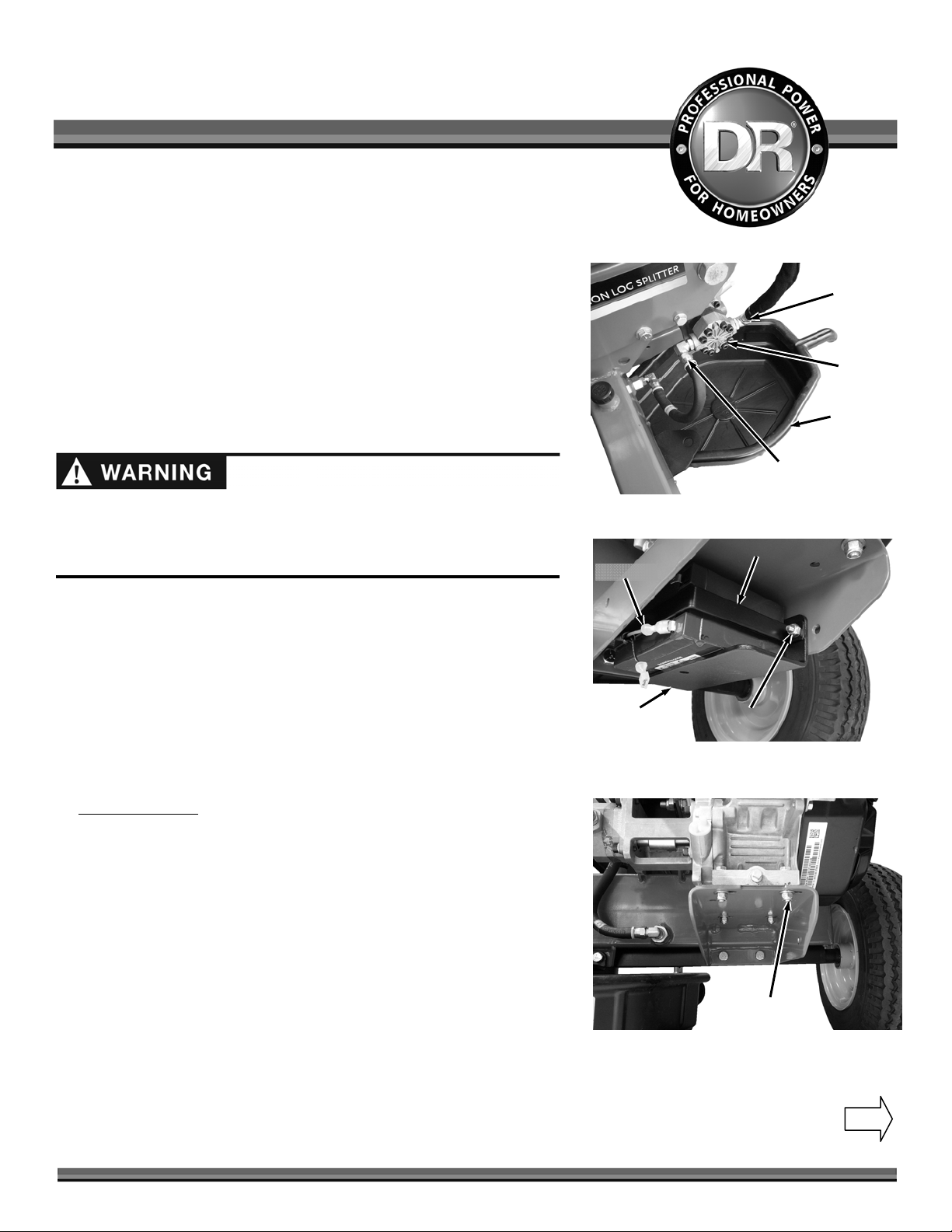
6. Remove the four Bolts, Washers and Locknuts from the Engine Mount with
two 1/2" Wrenches and remove the Engine with Pump (Figure 3).
Note: The Engine was mounted using the four slotted holes on the mount, but the
Motor will use the four round holes.
Dual-Action Gas to Electric Conversion Kit# 295171
Disconnect the Terminals from the Battery (Figure 2).
Engine
Hardware
Figure 3
Continued on
other side
Page 2
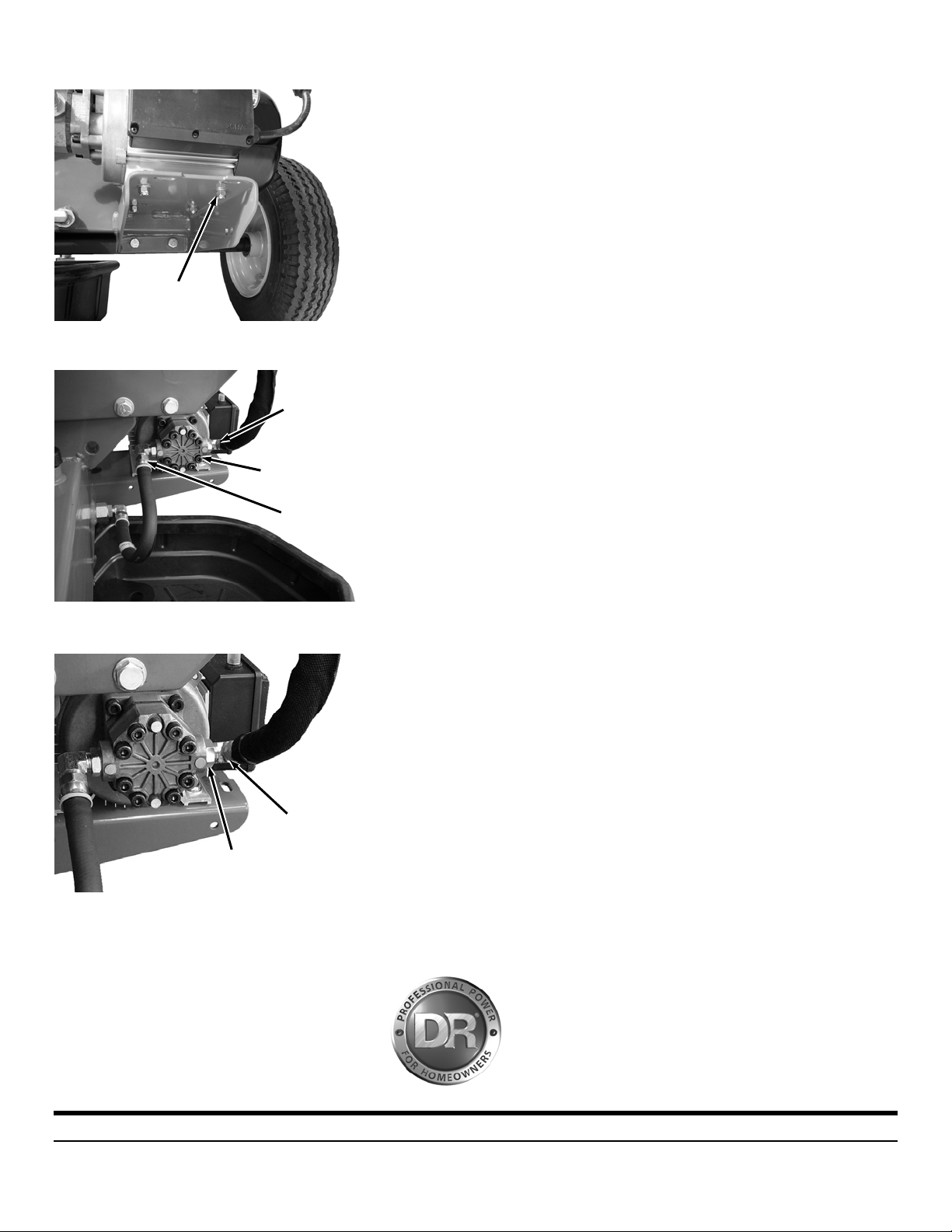
Figure 4
J
Motor
Motor
Hardware
Pressure
Hose
Connection
Pump
Intake Hose
Connection
7. Position the Electric Motor with Pump onto the Frame Mount and secure
with the new Bolts, Washers (one Washer on Bolt side and one on Locknut
side) and Locknuts using two 1/2" Wrenches (Figure 4).
8. Remove the plastic protectors from the Pump Elbow threads.
Note: The angle of the Elbows is set at the factory and should be at the correct
position to connect the Hydraulic Hoses. If however you are unable to connect a
Hose to the Elbow, due to the angle, an adjustment is required. Go to “Elbow
adjustment” at the end of this document. If the Hoses will connect with no
adjustment, continue to the next step.
9. Connect the intake Hose at the Intake Elbow with a 7/8" Wrench (Figure 5).
10. Connect the Pressure Hose at the Elbow with a 19mm Wrench.
Refer to your new Dual-Action Electric Log Splitter Safety and Operating
Instruction manual to cycle and check fluid level before continuing with the
Operating section of the manual.
If you have any questions please contact us at www.DRpower.com or call 1-800DR-OWNER (376-9637) for assistance.
Elbow Adjustment (Only perform if the Hose will not reach the
Elbow due to Elbow angle)
These adjustments work for both elbows on the Pump.
Figure 5
Figure 6
am Nut
Elbow
Tools and Needed:
24mm Wrench
1. Loosen the Jam Nut with a 24mm Wrench and back it off until it stops
(Figure 6).
2. Screw the Elbow into the Pump all the way so the Washer is against the
Elbow and Pump.
3. Turn the Elbow back to the angle needed to attach the Hose.
Note: Do not turn the Elbow back more than one full turn when adjusting.
4. Tighten the jam nut against the Pump and return to step 8 of the kit
installation above.
75 MEIGS ROAD, P.O. BOX 25, VERGENNES, VERMONT 05491
©2011 Country Home Products, Inc. All rights reserved 276331
 Loading...